Morse Code Beacon
Revised 10/25/2005
Last April I was given the opportunity to present two workshops at the East Coast Large Scale Train show in York, PA. One of the workshops focused on using microprocessors to simplify designing and creating electronic devices and controls for many different aspects of garden railways. (The notes from those presentations are available on my web page at www.davebodnar.com – click on 2005 ECLSTS notes)
The first part of the workshop showed how easily one can solder together an 8 pin microprocessor with a few LEDs and resistors to make a flashing crossing signal, a topic I have touched upon more than once in this forum. While I was putting together the presentation and working on the software that was used to blink the lights it occurred to me that the same circuit and LEDs could be used for a number of different tasks with little or no modification to the hardware. All that needed to be changed was the software, the microprocessor’s program.
One such modification to the circuit was the subject of a recent LSOL article on how to illuminate a lighthouse. In that discussion a microprocessor was used to gradually increase the brightness of a lamp, briefly flash it to full brightness and gradually shut it down simulating the light that is seen from a rotating lighthouse.
My other thought for an alternative use for this circuit came to me because of the Grant Building in downtown Pittsburgh. Since 1929 it has had a large tower at its top that flashes out “P-I-T-T-S-B-U-R-G-H” in Morse code. For decades it has been used by pilots as a navigational beacon since it can be seen from as far as 150 miles away. (For more information on the Grant Building click here: http://www.skyscraperpicture.com/pittsburgh2.htm )
This memory coupled with my being an amateur (ham) radio operator made this a must-do project!
I was sure that with some software enhancements the Picaxe would be able to send out a beacon in Morse code either by flashing a light, by making sounds or both.
I contemplated writing the software to generate Morse code from scratch but quickly came to my senses and spent a very productive hour on the Internet searching for existing programs that I could modify for my purposes. I found more than a dozen programs. The best of them is explained below.
Hardware
The hardware to produce a flashing Morse code beacon couldn’t be simpler.
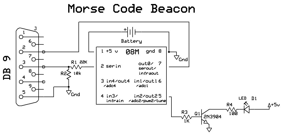
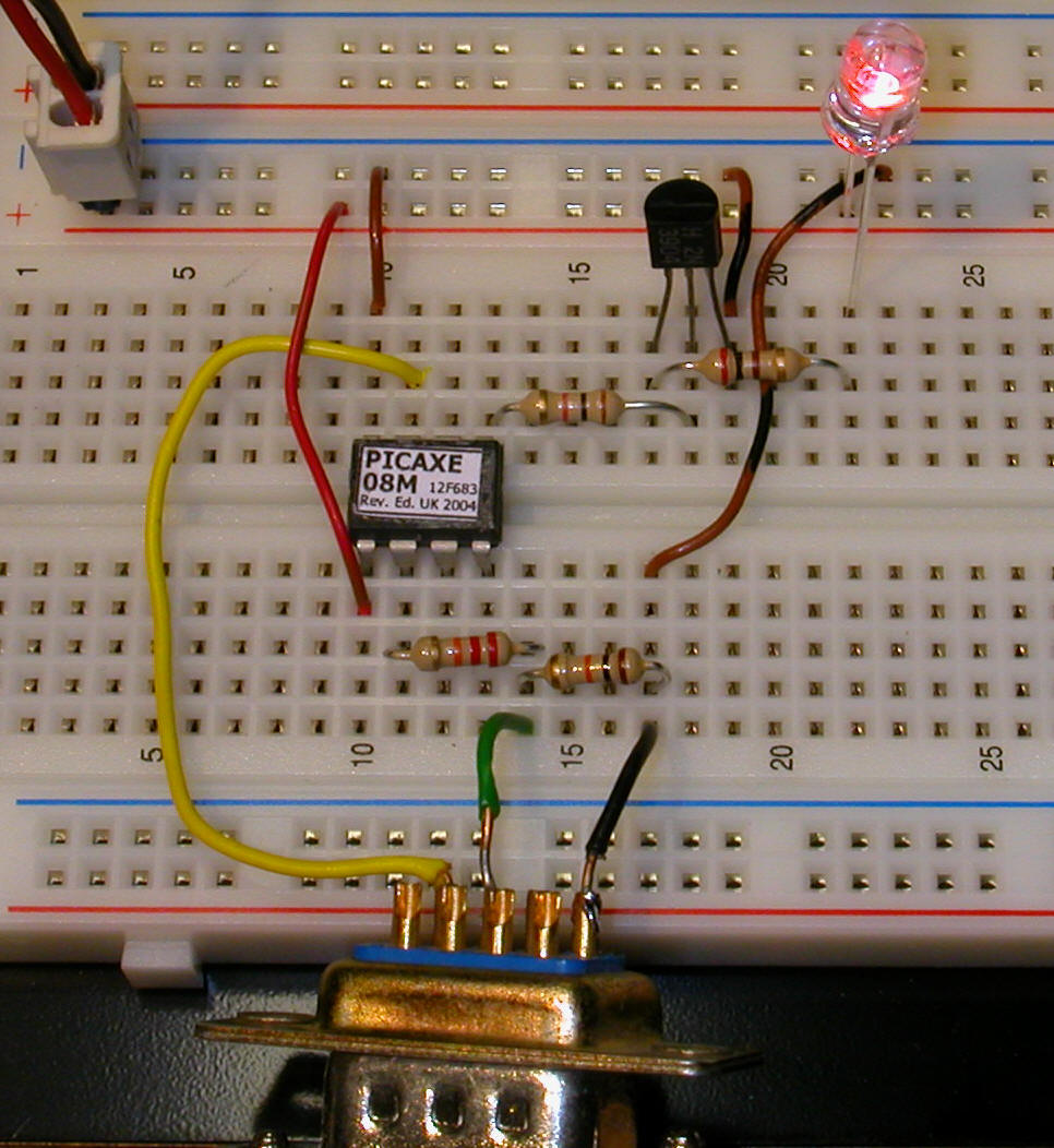
If you are satisfied with the light intensity generated by an LED all you need is the Picaxe, a battery, a transistor, an LED and a few resistors. (Note that there are sources for very bright red and white LEDs at the end of this article.)
In the schematic above the circuitry to the left, including the DB9 and two resistors, is needed only for programming. The LED is connected to pin 5 on the Picaxe through a 100 ohm resistor and a small NPN transistor. You could probably make the circuit even simpler and get away with connecting the LED and the 100 ohm resistor directly to pin 5 but it is safer to have the pin activate the transistor which then activates the LED. This also gives you the option of connecting several LEDs in parallel for a more intense light, as we did in the lighthouse project, without fear of damaging the Picaxe. Keep in mind that each pin on the Picaxe can only supply a limited amount of current. Power is supplied by a 4.5 volt battery pack made up of 3 AA batteries wired in series. You could also use 4 NiCad or NiMh cells in series giving 4.8 volts. You can use any combination that supplies a voltage between 3 and 6 volts.
MOVE SOFTWARE HERE?
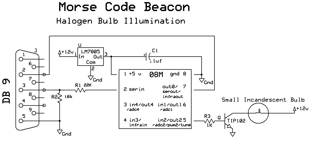
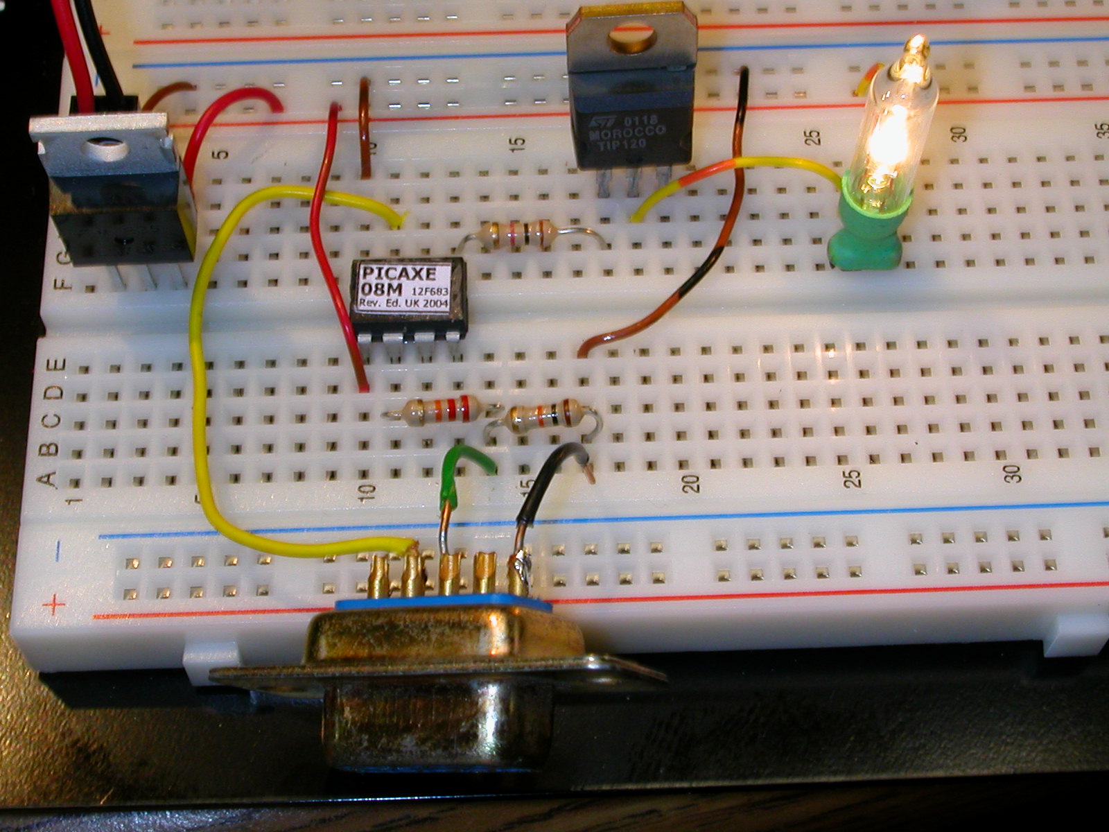
The second schematic shows the first circuit with two modifications. First is the 7805 voltage regulator that allows you to power the circuit from a power supply that provides 8-20 volts DC. Please see my article on regulated power supplies (5 Volt Power for Railway Electronics ) for more information on how this operates. The second modification is using a small incandescent bulb in place of the LED. This requires the use of a much larger transistor, the TIP102 or TIP120, that can handle the current drawn by the incandescent bulb. For my beacon I used a single clear bulb from an old string of Christmas tree lights. The ones I found worked well with 5 volts. I tested bulbs by cutting one out of a bad string and applying first 1.5 volts from a single AA cell then 3 volts from two cells and so on until I found a voltage that gave a nice bright light.
If you find a bulb, like I did, that works on the 5 volts provided by the 7805 just connect the one terminal of the bulb to the collector of the transistor and the other terminal of the bulb directly to the 5 volt output of the 7805. If you find a bulb that matches the output of your power supply, 12 volts in the diagram above, just connect the 2nd bulb terminal directly to the 12 volts from the power supply. You may need to experiment a bit to find a bulb that works well. Note that halogen bulbs work very well on the lighthouse but not in this application. They don’t go on or off very quickly and reproduce the dots and dashes poorly. Most Christmas tree bulbs, on the other hand, seem to be designed for being flashed on and off.
Solar Power
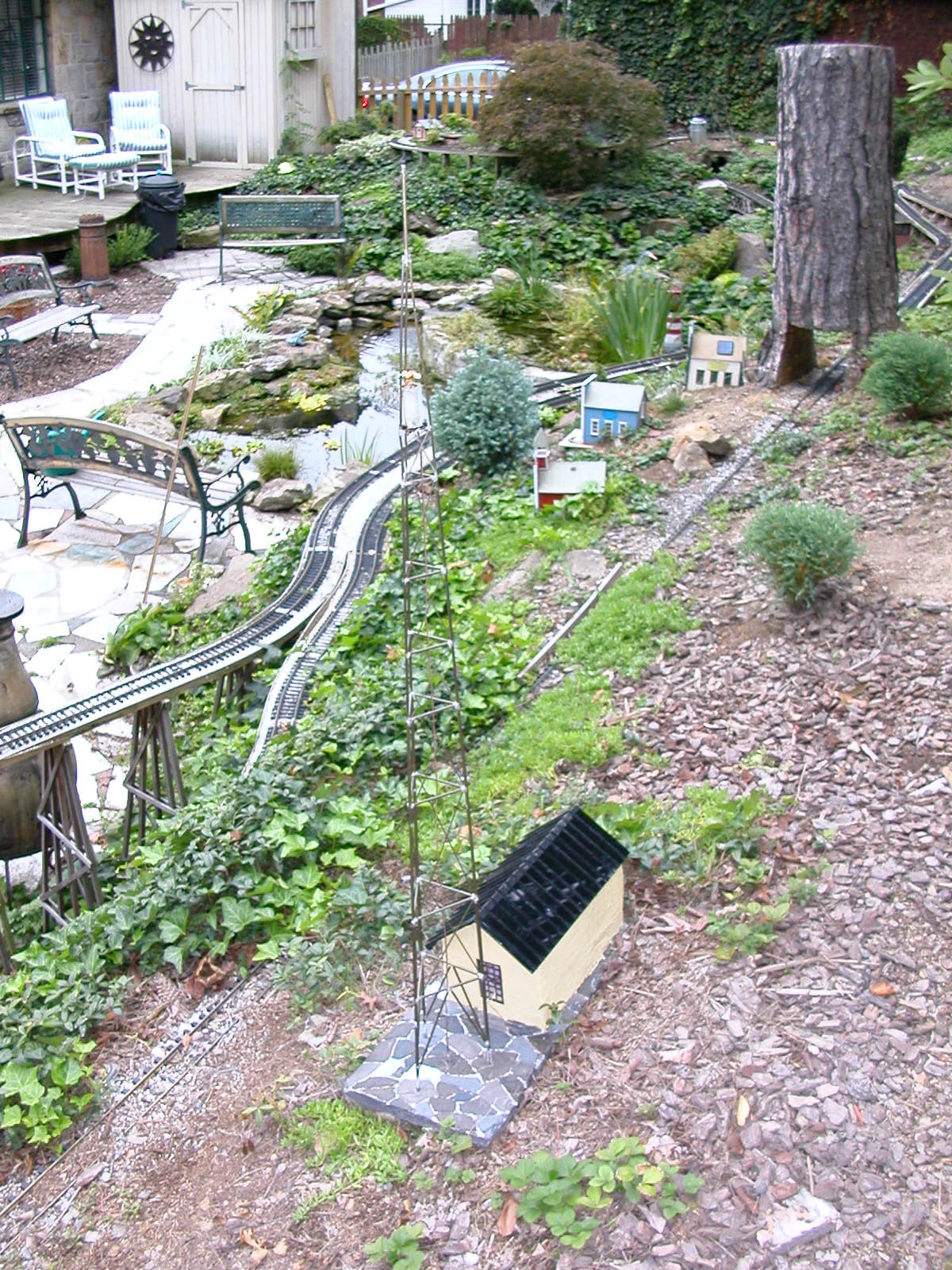
As is usually the case there are a number of enhancements that can easily be added. The Morse code beacon that I have at the top of a tower in my back yard has several.
First of all it operates strictly from solar power. If you read my article on using larger solar panels (LED Lighting with Larger Solar Panels ) the circuit below should look familiar. I used one of the large Harbor Freight solar panels described in that article and 8 NiCad AA cells wired in series. The only other thing that is needed is a single diode to keep the batteries from discharging through the solar panels at night. This is a great project for solar power as the LED beacon draws very little current and spends more time OFF than ON.
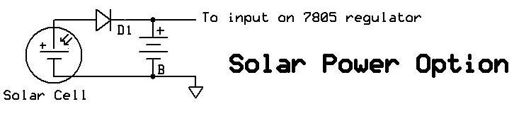
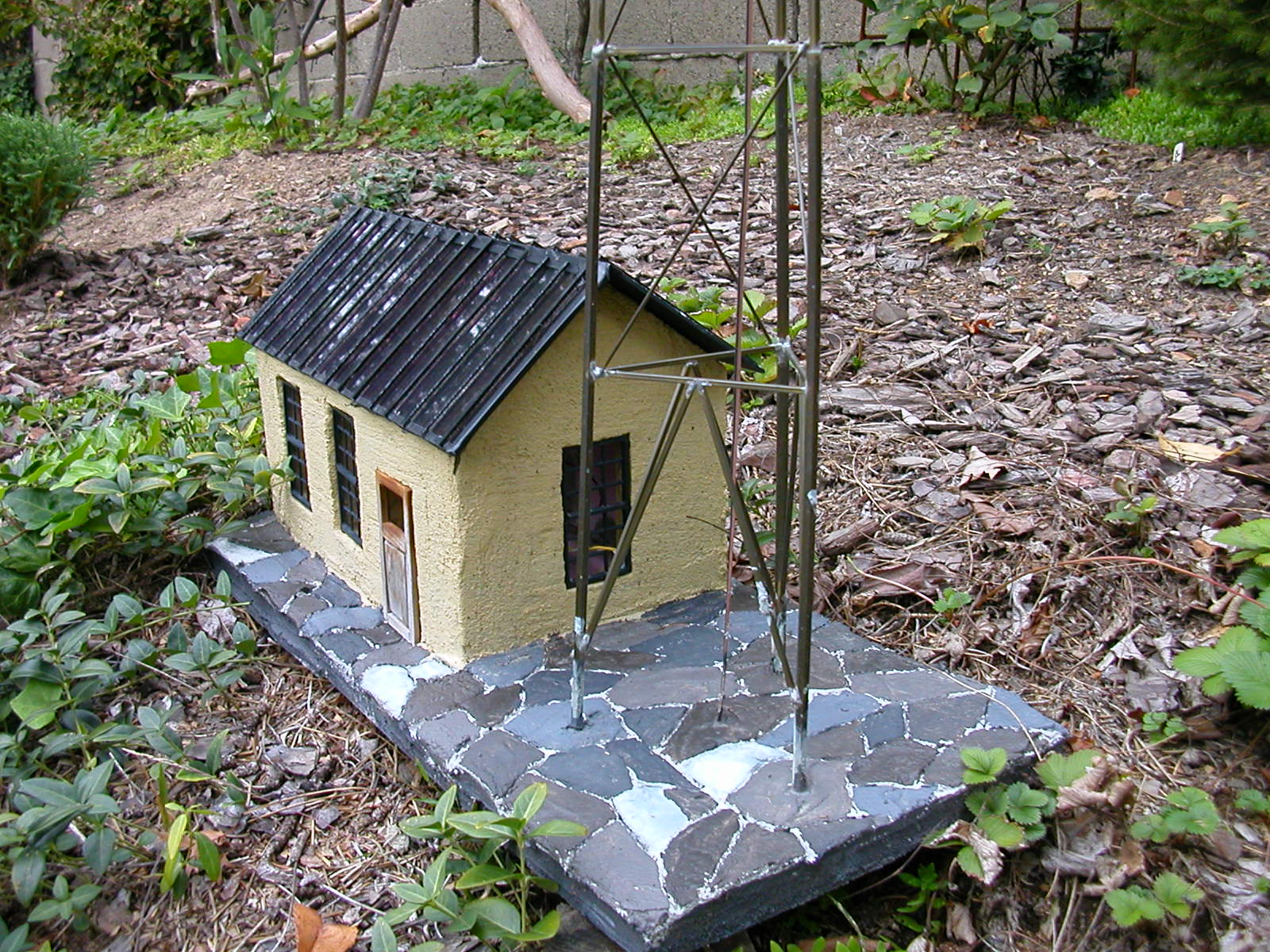
As you can see in this photo the Harbor Freight solar unit looks great as the front panel of the roof on the radio tower building. This solar powered beacon has been working 24/7 for more than 6 months without a problem, other than confusing the neighbors a bit. Note that no software modifications are necessary.
Different Beacons for Day and Night
Another modification has my beacon use 5 bright white LEDs during the day and 5 bright red LEDs at night. I have the white LEDs wired in parallel and soldered together and placed so that they look out to the sides of tower. This gives an observer's eye a better chance of getting a direct beam from an LED so that it might be visible in direct sunlight. At night it reverts to red LEDs which give a more pleasant look in the dark.
Adding this capability requires modifications to both the hardware and software. The only item that we have not used much before is a CDs photocell. These photocells are used in many light control devices as they are inexpensive, reliable and easy to interface into a circuit. CDs cell are sometimes referred to as photo resistors since their resistance changes depending on the brightness of the light that falls on them. In total darkness they can have a resistance of many hundreds of thousands of ohms. In bright light their resistance drops to a few ohms. In the schematic below the CDs cell is connected to pin 4 on the Picaxe.
Adding a CDs cell to the Picaxe only requires that we connect one wire from the CDs cell to an input pin on the Picaxe and the other to + 5 volts.
The "daytime" LEDs are connected to Picaxe pin 5 and the "nighttime" LEDs to pin 6. R5, a 10 K resistor, is connected to ground so that the pin is held to a low state until light falls on the CDs cell.
![]()
Software
The program that I am using for the Picaxe is one that I found on the Internet. It was part of an article in Silicon Chip magazine, an Australian publication, in August of 2003.
I received permission from the author, Stan Swan, to include the program in this article. His very well commented code is below.
| 'PICAXE-08 memory workout demo via
Eric van de Weyer & Stan.SWAN Ver 1.02 27th June 2003 'For Silicon Chip August 2003 PICAXE article. Author - Stan.SWAN => s.t.swan@massey.ac.nz 'Ref. Edwin.C =>chick@chickene.freeserve.co.uk -June 2002 RSGB "RadComm" "28" version too 'Program (derived from a Basic Stamp-1 idea ) sends short repeating Morse Code ID message '---------------------------------------------------------------------------------------- 'Almost unbelievably up to ~35 Morse characters can be stored in the tiny PICAXE-08 RAM ! 'Output here just simple Piezo speaker at PICAXE Pin 0, but could be used to key a Tx etc 'Only other component needed = 10k pull up R pin 3 to +ve rail to avoid "floating" 1/0 'Note - although now near obsolete for messages,International Morse Code ( CW ) still has 'wide use for beacons etc since decoding can be via eye or ear,& even unskilled observers 'can thus "read" simple IDs & status at just a few (5?)words per minute.Of course sending 'SOS via torch etc still suits emergencies! Scouting days now long past? Morse chs.are... ' A .- B -... C -.-. D -.. E . F ..-. ' G --. H .... I .. J .--- K -.- L .-.. ' M -- N -. O --- P .--. Q --.- R .-. ' S ... T - U ..- V ...- W .-- X -..- ' Y -.-- Z --.. 1 .---- 2 ..--- 3 ...-- 4 ....- ' 5 ..... 6 -.... 7 --... 8 ---.. 9 ----. 0 ----- ' Full stop .-.-.- Comma --..-- Slash -....- ' 'By tradition 1 dah/dash = 3 dits/dots with letter space = 3 dits & word spacing 7 dits ' 'How DOES this work !? Each ch.to be generated is programmed in as a number whose binary 'equiv. then generates the code ! The 5 MSBs(Most Significant Bits =LHS)represent dots & 'dashes, with dit=0 & dah=1. The last 3 LSB (Least Significant Bits = RHS) indicate how 'many elements in a ch. Hence V=00010100 (100 =4 elements). Bit 5 is meaningless here. 'Converting to decimal yields 20. Another ? K=10100011 = decimal 163 ( 011= 3 elements) 'Here's is a list of these characters (abrev. as ch. in comments) & their equiv. number '------------------------------------------------------------------------------------- 'A - 66 B - 132 C - 164 D - 131 E - 1 F - 36 'G - 195 H - 4 I - 2 J - 116 K - 163 L - 68 'M - 194 N - 130 O - 227 P - 100 Q - 212 R - 67 'S - 3 T - 129 U - 35 V - 20 W - 99 X - 148 'Y - 180 Z - 196 1 - 125 2 - 61 3 - 29 4 - 13 '5 - 5 6 - 133 7 - 197 8 - 229 9 - 245 0 - 253 '= - 141 / - 149 . - 86 , - 206 ' 'Encode to suit - thus "AUSTRALIA 2003" = 66,35,3,129,67,66,68,2,66,0,61,253,253,29 '------------------------------------------------------------------------------------- 'Copy & paste main program below to "08" editor via=> www.picaxe.orcon.net.nz/morse.bas 'Still scope for "telemetry" or tweaking SLEEP/NAP,as only 105 bytes (of 128)used as is! '------------------------------------------------------------------------------------- ' Symbol Tone = 100 'sets the tone frequency ( range 20 -127 ) Symbol Quiet = 0 'set quiet tone Symbol Dit_length = 7 'set length of a dot (7 milliseconds)- yields 10wpm Symbol Dah_length = 21 'set length of a dash (21 mS = 3 dots long) Symbol Wrd_Length = 43 'set space between words (43 mS = 2 dashes, 6 dots) Symbol Character = b0 'set register for ch. Symbol Index1 = b6 'loaded with number of chs. in message Symbol Index2 = b2 'counts the number of elements Symbol Elements = b4 'set register for number of elements in ch. Start: 'NB - good program spot to turn on ID, via sensor etc maybe? Identify: ' routine to lookup ch.& put its value into the ch. register for Index1 = 0 to 9 'cycle through lookup for times = number of ch. in message lookup Index1,(100,2,129,129,3,132,35,67,195,4),Character ' The line above means P I T T S B U R G H gosub Morse 'go to the ch. generation routine next 'loop back to get next ch. and load it goto Start 'return to start to wait for next input Morse: let Elements = Character & %00000111 'look at 3 LS digits and load into Elements register if Elements = 0 then Word_sp ' % means binary Bang_Key: for Index2 = 1 to elements 'loop through correct no. of times for number of elements if Character >= 128 then Dah 'test MS digit of ch. If it is 1 goto the Dah sub routine goto Dit 'if it is 0 goto the Dit sub routine Reenter: let Character = Character * 2 'do a left shift on all the bits in ch. next 'loop back to get the next element gosub Char_sp 'go to sub routine to put in inter-ch. space return 'return to Identify routine to get next ch. to send Dit: sound 2,(Tone,Dit_Length) 'sound tone for dit length sound 2,(Quiet,Dit_Length) 'silence for dit length goto Reenter 'return to look at next element of ch. Dah: sound 2,(Tone,Dah_Length) 'sound tone for dah length sound 2,(Quiet,Dit_Length) 'silence for dit length goto Reenter 'return to look at next element of ch. Char_sp: sound 2,(Quiet,Dah_Length) 'send silence for dah length after ch.completely sent return 'return to get next character Word_sp: sound 2,(Quiet,wrd_length) 'send silence for break between words return 'return to get next ch. |
The beauty of this program is the way that it stores the information for each Morse code character. It uses the first 5 bits of an 8 bit binary number (made up of 1’s and 0’s) to store the dot / dash information for each character and the last 3 bits to store how many dots and dashes there are. For example the letter “L” is “._..” . 0100 would represent dot/dash/dot/dot with zero (0) for a dot and one (1) for a dash. Since the Morse code representation of the letter is four characters long the end of its binary representation would be 100 which is binary for four. Finally, put it together: “0100” + an extra filler zero + “100” gives us 0100 0 100 (01000100) in binary which is 68 in decimal. The letter “R” would be 01000011, or 67 in decimal. The easiest way to decode 010000011 is to take the last three digits, “011” which equals three, and use that number as the number of characters to take from the “front” of the number. That gives us “010” as the code which is dot / dash / dot.
How about one last example? Give the letter “Y” a try yourself before reading the next sentence.
The letter “Y” is “_ . _ _” It would be 1011 at the front and 100 at the end with one filler zero in the middle or 10110100 which equals 180.
The program takes the information for each letter and decodes it and sends out the appropriate dots and dashes for each letter. Because of the compact nature of this program it is necessary for you to manually convert your message into the above code and enter it into the program. For example, “P I T T S B U R G H” would be:
100,2,129,129,3,132,35,67,195,4
There is a table showing each letter and its number at the beginning of the program.
Software Modifications
The program above can be used for the first beacon at the beginning of the article as well as the solar powered version. The only thing that you need to do is change the line:
lookup
Index1,(100,2,129,129,3,132,35,67,195,4),Character
so that it spells out your message. Use the table at the top of the program to select the numbers that represent the letters you want to use. For example, if you want to spell out "W-E-L-C-O-M-E--T-O--M-Y--R-A-I-L-R-O-A-D" you would change the line to:
lookup Index1,(99,1,68,164,227,194,1,0,129,227,0,194,180,0,67,66,2,68,67,227,66,131,0),Character
The 0's (zeros) between words just insert a short pause. You will also need to change the line before so that it reads the number of characters you have used, including the pauses. In this example it is 23 characters so the line changes to:
for Index1 = 0 to 22 'cycle through lookup for times = number of ch. in message
Note that the counting starts with 0 (zero) so the ending number is 22, not 23 as it would be if it started counting from 1 (one).
Two LED Modification
To use two LEDs you must add a few lines to the program. The first (readadc 4, voltage) checks the state of the CDs cell to see if light is falling on it. If it is then it will use the first set of LEDs, if it is in the dark the second set of lights is used. The sound command is used normally used to make "beeps" but in this program it is used to light the lights. In the original program it sent its pulses out on pin 2. For this modification we have to set it so that it can send its pulses out on either pin 1 or pin 2.
| Symbol Tone = 100 'sets the tone
frequency ( range 20 -127 ) Symbol Quiet = 0 'set quiet tone Symbol Dit_length = 7 'set length of a dot (7 milliseconds)- yields 10wpm Symbol Dah_length = 21 'set length of a dash (21 mS = 3 dots long) Symbol Wrd_Length = 86 'set space between words (43 mS = 2 dashes, 6 dots) Symbol Character = b0 'set register for ch. Symbol Index1 = b6 'loaded with number of chs. in message Symbol Index2 = b2 'counts the number of elements Symbol Elements = b4 'set register for number of elements in ch. Symbol voltage = b13 'adc variable to see if sun is out! Symbol whichLED = b8 readadc 4, voltage if voltage > 100 then sun: 'if over 100 it is day - use other LEDs whichLED=2 'in2 (pin 5) goto skipit: sun: whichLED=1 'in0 (pin 6) skipit: Identify: ' routine to lookup ch.& put its value into the ch. register for Index1 = 0 to 31' 1 'cycle through lookup for times = number of ch. in message lookup Index1,(131,1,0,130,29,1,130,194,0,0,100,0,2,0,129,0,129,0,3,0,132,0,35,0,67,0,195,0,4,0,0,0),Character 'the line above gives "DE N3ENM PITTSBURGH: gosub Morse 'go to the ch. generation routine next 'loop back to get next ch. and load it goto Start 'return to start to wait for next input Morse: Bang_Key: Reenter: Dit: Dah: Char_sp: Word_sp: |
Sound Rather than Light
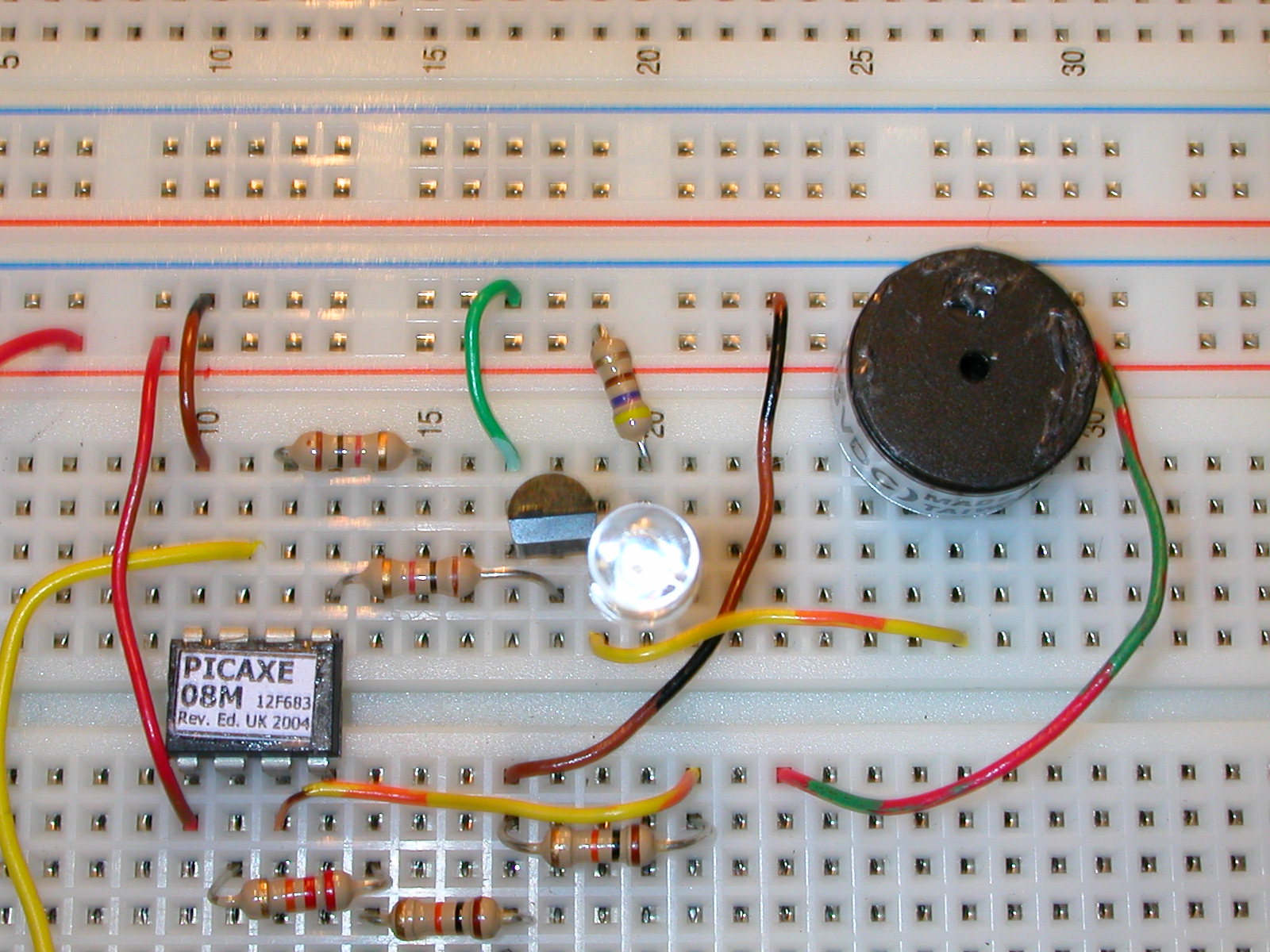
Another thing that you might want to consider is using the beacon to create Morse code sounds in place of or in addition to LED flashes. If you have a telegraph office or railway station in your layout the board could be connected to a simple piezo buzzer (see parts list) rather than an LED. Just remove the 100 ohm resistor and wire the positive terminal of the buzzer to plus 5 volts and the negative terminal to the emitter of the NPN transistor. In the setup below I have the positive lead of the buzzer inserted in the positive bus on the board and the negative lead connected to the collector of the transistor. That allows the buzzer to buzz and the light to light!
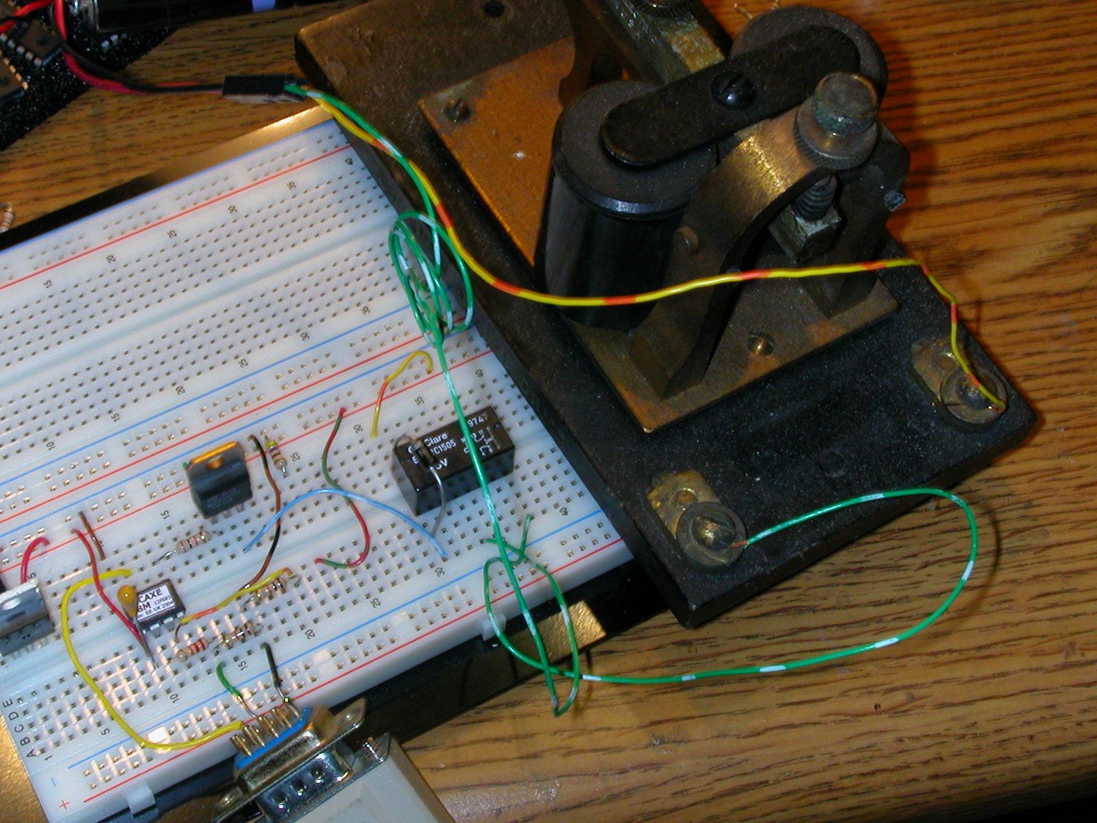
You could also experiment with driving other sounders such as a real telegraph sounder, as pictured below. I got mine working by substituting a small relay for the LED and using it to drive the telegraph sounder. It is important that you use a separate power supply, I used batteries, to power the antique sounder. The large spikes created by powering its coils on and off are likely to kill anything on the circuit that connects directly to it!
I also had to change the code a bit. The revised lines are below. The lengths for Dit, Dah and Word were multiplied by 10 and the sound command for Dit and Dah were changed to use High and Low, which give more solid latching of the relay contacts.
| Symbol Dit_length = 70 Symbol Dah_length = 210 Symbol Wrd_Length = 860 Dit: high 2:pause Dit_Length low 2: pause Dit_Length goto Reenter Dah: |
There is no better way to give your old railroad station the sound of a telegraph! Give it a try and let me know how it turns out!
See Part II for a More "User-Friendly" Version
Part II describes a simpler, yet more powerful, version of this project that requires no programming on the end user's part.
Parts
| Parts list:
Morse Code Beacon
Miscellaneous
The following items are available from the author: Bright LEDs I have bright amber, red and white 5 mm LEDs available. Their cases are clear. I also have bright red 3mm LEDs. These smaller devices are ideal for placement in engines and other items where space is a challenge.
Programmed Picaxe only. $6.00 + shipping (specify which of the programs in the article you want on the Picaxe) I have given Radio Shack part numbers for the parts used in this article but you are likely to find much better prices from other vendors, including Hosfelt ( www.hosfelt.com ), Digikey ( www.digikey.com ), Electronics Goldmine ( www.electronicsgoldmine.com ), Jameco ( www.jameco.com ) and Glitchbusters ( www.glitchbusters.com ) - I have links to these and other vendors on my web page at www.davebodnar.com .
|
-------------------PART II HERE ------------------
A More “User-Friendly” Version
When I was writing this article I gave some thought to those readers who would rather not solder together the components used for this project and edit the program to have it spell out their own greeting in Morse code.
In order to accommodate that part of the audience I developed a more complex program that will not work on the basic Picaxe processor, but on one of its big brothers, the Microchip 16F684 PIC processor.
One might be concerned by the phrase “more complex program” mentioned above but fear not! As is usually the case in situations like this a more complex program allows the end user to interact with the program in a simpler and more efficient way.
In this case the program allows you to reprogram the message by connecting the board to any computer’s serial port and running HyperTerminal or a similar terminal program.
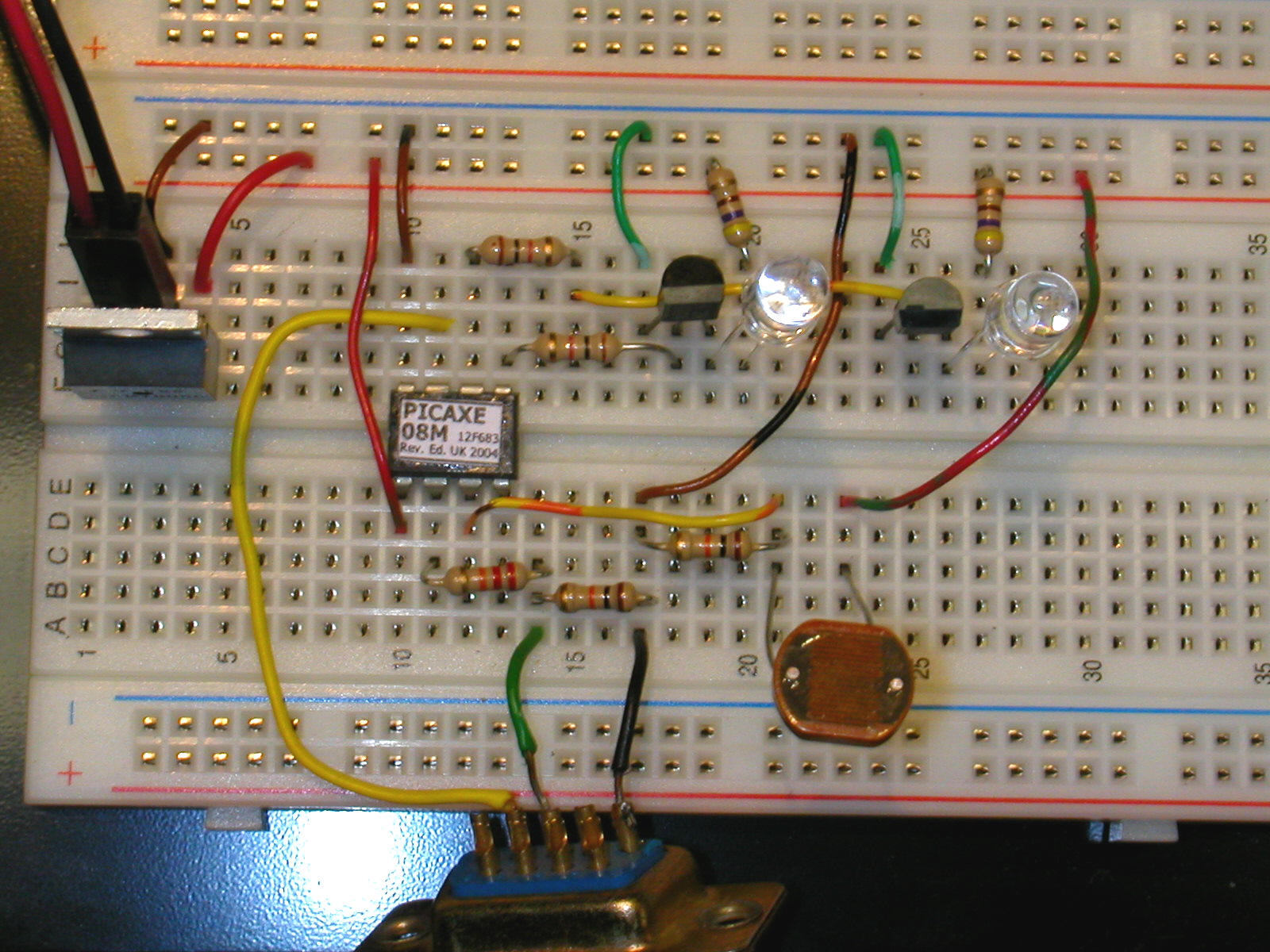
Hardware
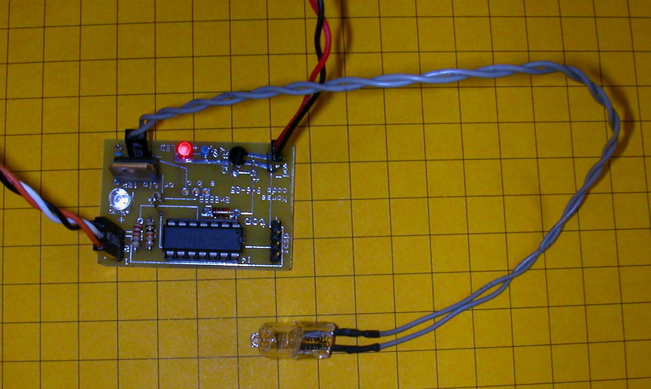
The hardware is similar to what was used with the Picaxe. The main parts include a circuit board, IC socket, 16F684 chip, voltage regulator, power transistor and power supply. The only additional part is the connection to a PCs 9 pin serial port. This is the path through which you can reprogram the chip to change its Morse code message. In the photo below the red and black wires in the upper right of the board connect to DC power, the 3 wire connector in the lower left connect to the computer's serial port and the bulb to be flashed connects in the upper left corner.
Software
The software is a bit too involved for a discussion here but I will be glad to share it with anyone who is interested.
Changing the Message
When the chip is first programmed its message is “W –E-L-C-O-M-E ---T-O---MY---R-A-I-L-W-A-Y” To change the message connect the serial connection on the circuit board to your PCs 9 pin serial port. If you have a fairly new computer it may have been delivered without a serial port since many systems rely on USB ports. If that is the case dig out an older PC or laptop that has a serial port. If you have a USB to Serial Port adapter you can give it a try but my experience has been that most don't work with this application.
Programming involves starting a terminal program, like HyperTerminal. Set it to 9600 baud, No parity, 8 bits, and one stop bit. It must also be set to use COM1 (or whatever com port you prefer) rather than a modem.
The images below show how I set up my computer. To get started on a Windows 98, 2000, ME or XP computer click Start then All Programs then Accessories then Communication then HyperTerminal. If HyperTerminal is not there you may have to install it. For instructions on how to do so just search Google for "Install HyperTerminal". Here is a sample link on how to do the install from IBM's web site.
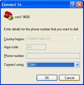
When you first start HyperTerminal you must create a new connection. Type a name for the new connection (I used Com1 9600) in the Name box.
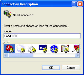
Click OK
Click OK if COM1 is available on your computer. On most it is.
Change the next screen so that it looks like this:
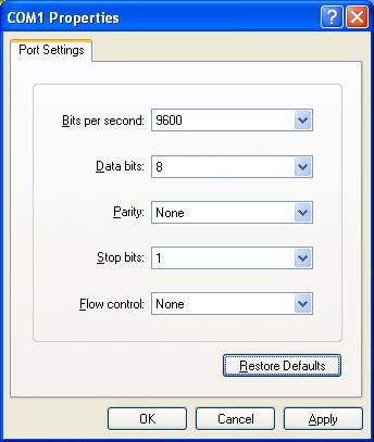
Click OK.
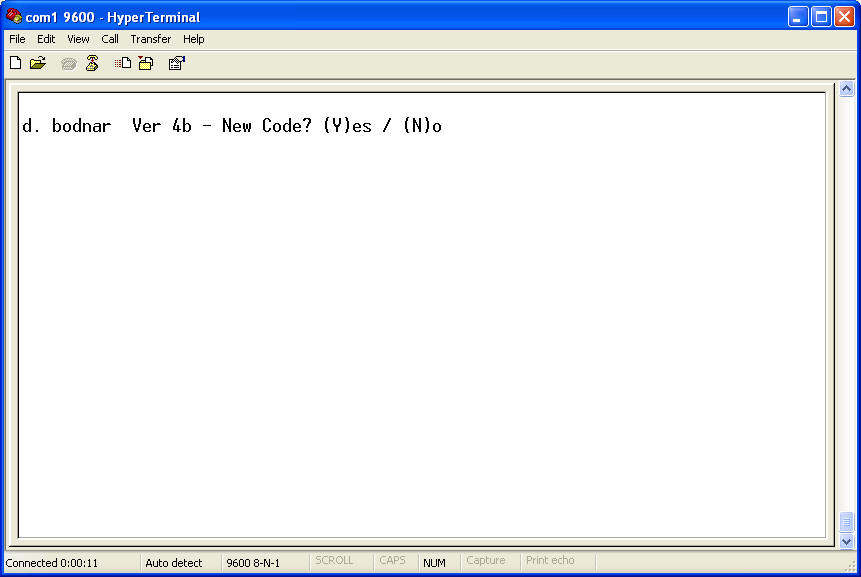
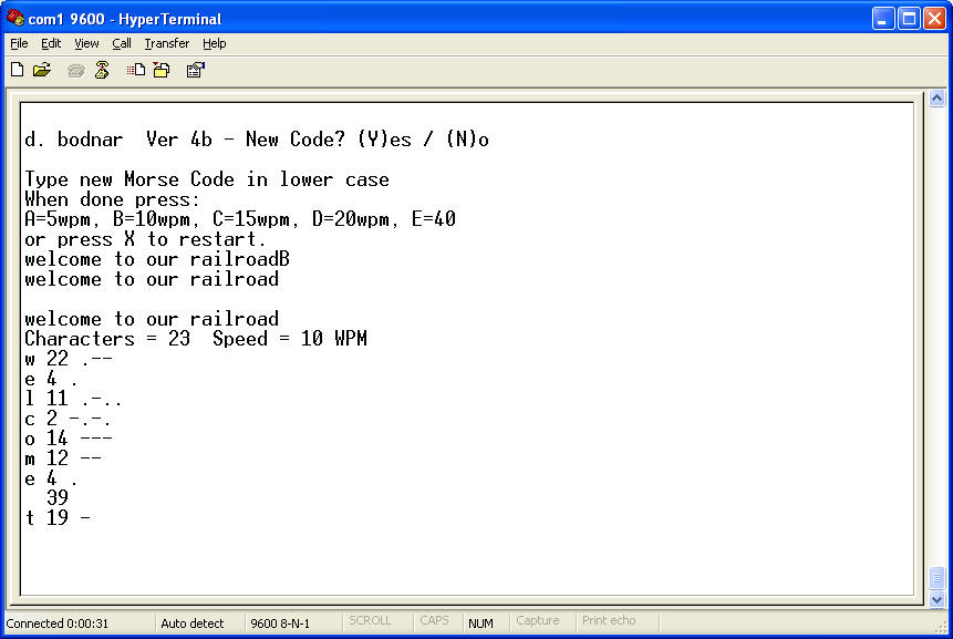
Connect the serial cable from the Morse code board to the serial port on the computer. If HyperTerminal is running while the circuit is powered up you will be asked if you want to change the message. Just press “Y” in response to the question "New Code? (Y)es / (N)o" to change the message.
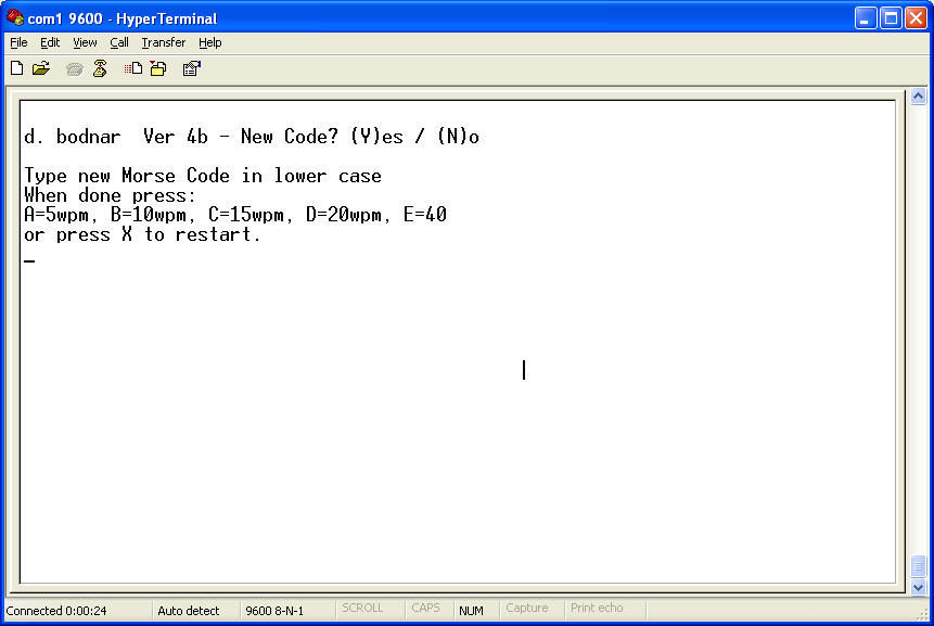
After you type "Y" you will be asked to type in your new message in lower case.
The Morse code beacon will accept up to 127 characters.
When you are done entering your message type "A" for a speed of 5 words per minute, "B" for 10 WPM, "C" for 15 WPM, "D" for 20 WPM or "E" for 40 WPM - make sure you use a capital letter!
As soon as you type one of the capital letters to indicate speed the beacon starts. To confirm that your message was entered correctly the program will spell it out on the screen as it sends.
If you press “Y” within a few seconds you can type in a new message. All of the letters for the new message MUST be in lower case. Upper case letters are used as control codes. To change the message to “a great day for trains” just type that message (using lower case) followed by a capital “Z” to save and exit. Note that you cannot backspace. If you make an error just power off / power on the circuit and start over.
Once the messages starts to send you can HOLD the ESC key on the keyboard to return to the programming mode.
Once a new message is programmed it will be used until a new message replaces it. The message will not be forgotten just because power is removed.
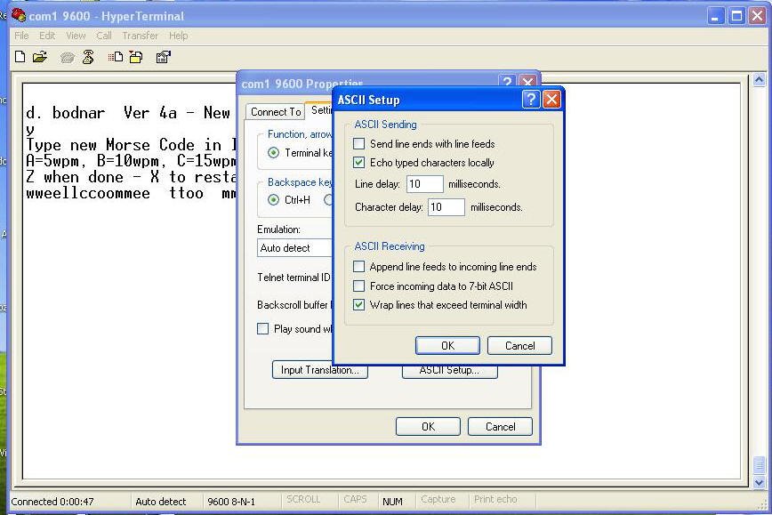
Double Characters on HyperTerminal
If you find you are getting double characters on the screen as you type a new message you need to turn off "local echo:. Click on File / Properties / Settings / ASCII Setup and remove the checkmark next to "Echo typed characters locally".
Beacon Mounting Ideas
As you can see from the pictures I have mounted my beacon at the top of a radio tower. The ones that I have built are made of brass tubing that is soldered together.
Other mounting ideas include putting the beacon on top of a tall building, as with the Grant Building. You could also mount the flashing light on the top of a water tower or any other tall structure.
The Morse code beacon greets me as I pull into my driveway every evening and every morning when I look out into the yard. You may want to have one do the same! Good luck with the project and let me know if I can help.