LED Lighting with Larger Solar Panels
Revised 10-29-04 5:13 am 7-22-12
Introduction
After illuminating many of my smaller buildings with the innards of Malibu solar walkway lights I needed to light several larger buildings. Rather than combining three or more of the Malibu lights I chose to find larger solar panels that would be able to supply power to six or more LEDs. The solar panels and circuitry described here provide an easy way to automatically keep your buildings illuminated for many hours each evening, especially after a sunny day of solar charging!
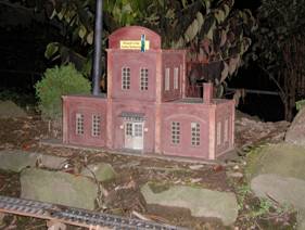
coffee_refinery_flash.JPG 1
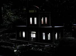
coffee_refinery_LED.jpg 1
Solar Panels
I have found two reasonably priced sources for solar panels. Harbor Freight (www.harborfreight.com) sells small solar panels that are designed to trickle charge a car’s battery. The panels are about 6” x 15” and are attached to a cable that ends in a cigarette lighter plug. The idea is to place the panel on a car’s dashboard and plug the other end into the cigarette lighter socket. If there is sufficient sunlight it will help to keep the battery charged.
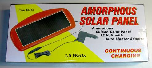
HF_Box.jpg 1
The Harbor Freight panels normally sell for $20.00 each but they are frequently on sale for ½ of that. On their web page search for item: 44768-2VGA. When not connected to a load the panel puts out more than 20 volts in direct sunlight. This drops dramatically when connected to a battery. I measured 100 milliamps when charging a 7.2 volt battery pack in direct sunlight. That should be more than enough to give several hours of illumination, depending on how many LEDs you have in the circuit.
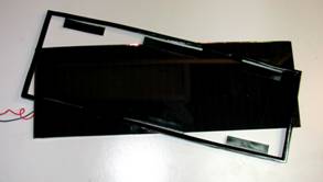
It is much easier to conceal this unit if you separate it from its bright red enclosure. Removing 11 screws from the back of the case reveals the 4.25” x 12” glass panel to which the cells are bonded. Protect the edges of the glass with tape or a layer of black silicon seal. Another option is to reuse the beige rubber edging, seen in the photo, after painting it black so that it is less visible.
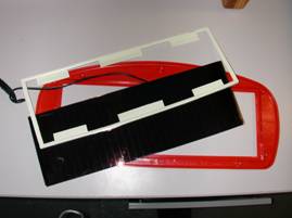
HF_inside_2.jpg 1
HF_painted.jpg 1
VW Panels from eBay
My other source for solar panels is eBay. It seems that every Volkswagen that is shipped to the United States has a solar panel attached to the inside of its windshield with several suction cups. It also uses a cigarette plug to keep the battery charged. I am not sure how much sun gets into the holds of a freighter, maybe they are depending on the time that the cars sit in parking lots before and after their ocean voyage. Just search eBay for “VW solar” and you should find a number of these units. They typically sell for about $15.00 each.
The VW panel has a rating of more than double the output of the Harbor Freight unit, 3.2 watts vs. 1.5. My tests prove this out as it delivered nearly 250 milliamps when charging the same 7.2 volt battery in direct sunlight.
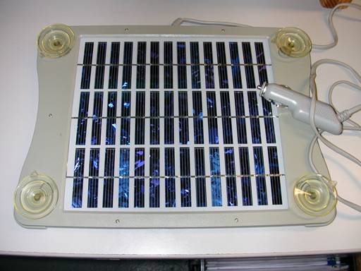
VW_1.jpg 1
These panels also come apart after removing screws from the front and back of the case. Again, it is wise to protect the edges with black tape. As an added bonus, I found that the panels were much less noticeable if I covered the white edges.
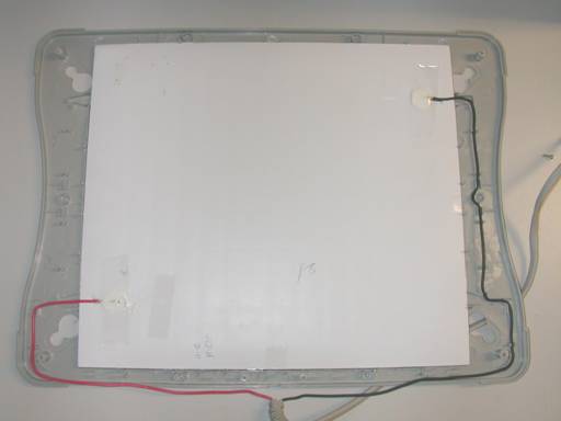
VW_inside1.jpg 1
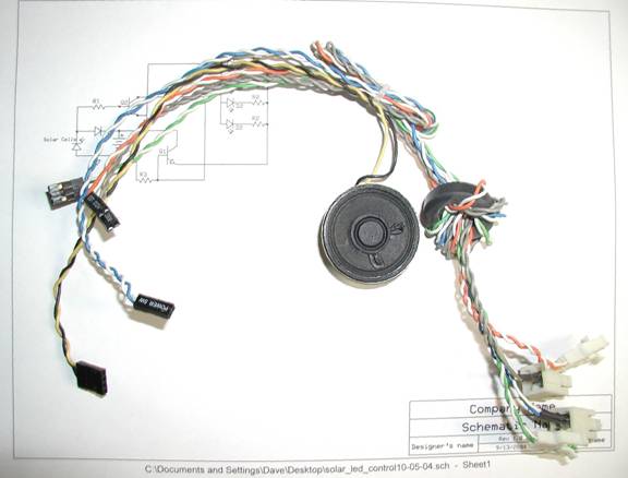
Circuit
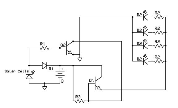
The circuit has two jobs. It charges the batteries when sunlight is present and turns the LEDs on when darkness comes. This is accomplished with two transistors, a diode and a few resistors.
The solar panel, diode D1 and the battery make up the charging circuit. When voltage is being generated by the solar panel it charges the batteries through D1. When the panel is dark D1 keeps the batteries from discharging through the solar panel.
Transistors Q1 and Q2 turn the LEDs off and on. You may recall that a transistor is simply a switch with three leads, base, collector and emitter. When voltage is applied to the base lead the transistor turns ON and voltage is allowed to pass from the collector to the emitter. In this circuit when voltage is applied to the base of Q2 from the illuminated solar panel it connects the base of Q1 to ground, turning it off. When the sun goes down and Q2 is off, voltage begins to flow from the battery through R3 to the base of Q1 lighting the LEDs.
The LEDs, D2, and current limiting resistors, R2, are wired in parallel. Make sure that the long, positive LED lead is connected through R2 and then to the emitter of Q1.
The values of the resistors are not critical. For example, increasing the value of R1 will cause the lights to come on earlier in the evening as it limits the voltage coming from the solar panels to the base of Q2. During development I substituted a variable resistor for R1 to determine a good value.
solar_cropped.JPG 1
Parts
In addition to the solar panel you will need the following parts:
2 @ NPN transistor – 2N2222 (Radio Shack Catalog #: 276-2009 $0.69) or 2N30904 (Radio Shack Catalog #: 276-2016 $0.69)
6 @ AA NiCad or NiMH cells
1 @ 1N4001 diode (Radio Shack Catalog #: 276-1101 $0.59)
4-6 @ high output LEDs (see text)
2 @ 1000 ohm resistor (R1 and R3)
4-6 @ 330 ohm resistor (R2) (see text)
1 @ circuit board (see text)
Batteries
When choosing batteries note that NiCad cells have a lower power rating but they can be charged / discharged up to 1000 times while NiMH cells are generally rated at half that many cycles. This is a great place to use old NiCads that you may have laying around. I have used old 6 cell, 7.2 volt NiCad packs that were no longer good enough for radio control race cars but are just fine for this purpose.
LEDs
High output LEDs can be obtained from a number of sources including:
Hosfelt Electronics (www.hosfelt.com )
Radio Shack
Battery Space (http://batteryspace.com)
A very cost effective source is described in an article previously on LSOL that deals with low cost (dollar store) USB laptop lights.
If you do use discrete LEDs, rather than the USB lights from the dollar store, you will need to add a current limiting resistor. The value for this resistor varies from device to device but is usually in the 330-1000 ohm range. The resistor should limit the current going to the LED to its published operating current. Experiment a bit. Start with a 1000 ohm resistor and measure the current with a multi-meter. If it is low decrease the resistance until it is in the right current range. You will also note the LED is likely to brighten as the resistor value drops. If you reach a point where brightness ceases to increase stop there as any additional increase in current will just be dissipated as heat and will eventually destroy the device.
Note that this resistor, R2, should be used with each LED that is powered by this circuit. That is, you need to add an individual resistor in series with each LED that you connect. It is possible to use just one resistor with a group of LEDs, but the brightness of the LEDs may vary if they are not identically matched. The best practice is to use a separate resistor for each one. Remember, if you are using the LED lights from the USB laptop lights no resistor is needed as these LED lights have a built in current limiting resistor.
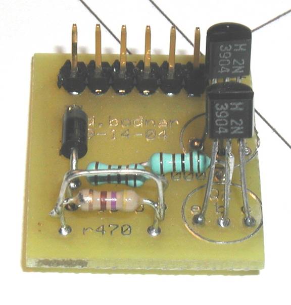
There is a place for R2 on my circuit board and it can be installed for testing with one LED. Once you put the unit into service and use it with a number of LEDs, each with a resistor, just solder a jumper over the resistor to bypass it as shown in the photo.
board1.JPG 1
Construction
Connect the devices as in the schematic. This can be done on a piece of circuit board, such as Radio Shack Catalog #: 276-150 ($1.79) or you can use the custom circuit board that I have made for this project.
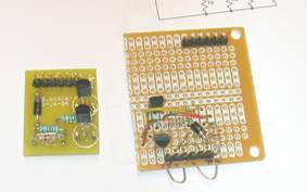
both_boards.jpg 1
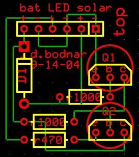
pcb_all.JPG 1
Please contact me at dave@davebodnar.com for price and availability. Take care to place the diode correctly. The band at one end goes to the positive terminal of the battery.
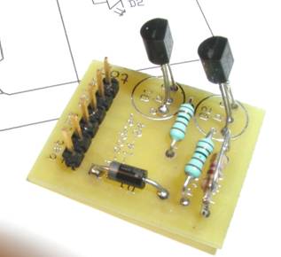
board3.JPG 1
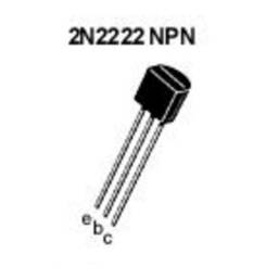
2n2222b.jpg 1
The transistors must be placed so that the emitter, collector and base are in the right holes on the circuit board.
On my circuit board I have used a 6 pin header to connect the wires from the battery, solar panel and LEDs. This is convenient for prototyping and testing but is not necessary for a permanent installation. Wires can just as easily be soldered directly to the board. If you would like to use the header but don’t have the plugs that fit over the pins you can find an unlimited supply of them in old computer cases. Similar headers are used on computer motherboards. Before permanently retiring an old PC salvage the plugs and lengths of wire
pc_cable.JPG 1
Testing
Connect the batteries and one LED to the circuit. The LED should light since there is no voltage in the circuit from the solar panel. Connect the solar panel and expose it to light. The LED should go out. Covering the solar panel should bring the LED back to life.
Installation
There are a number of ways to mount the solar panels. If you are using the Harbor Freight panel and have removed it from its enclosure the simplest mount is just to glue a pair of triangular braces to the back of it to support it at an angle on the ground.
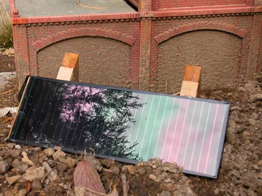
HF_coffee_outside.jpg 1
This panel is also easy to use as half of a building’s roof. Just remember to keep the panel pointed as much to the south as possible and to tilt it upward at about 45 degrees.
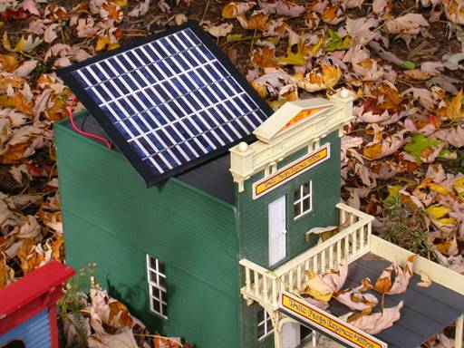
VW_on_WFoffice.jpg 1
Either panel can also be used as a flat roof on a building. Just remember to place it so that it gets as much sun as possible and clean dirt and other debris off from time to time.
Before installing the circuit in a building the board should be put into an enclosure to protect it from moisture. An old film can or pill bottle should suffice.
Adding Track Power for Charging
Please make sure that you are comfortable with everything that is discussed below as an error in wiring or components in this circuit has the potential to damage your power supply. In addition, delivering too high a charging rate will heat the current limiting resistor to a very high temperature and can damage batteries very quickly. Make sure you use a meter to test the current being delivered to the battery before putting it into service!
If your trains run under track power, a simple modification to the circuit allows for quicker charging of the batteries while your trains run. This could come in handy if you are having friends over during the winter months and want to show off your lighted buildings but clouds have kept the time that they are illuminated down to a few hours.
The additional components are:
1 @ 1N4001 diode (Radio Shack Catalog #: 276-1101 $0.59)
1 @ bridge rectifier (Radio Shack Catalog #: 276-1152 $1.49)
1 @ 1 watt resistor (see text)
1 @ 2200µF 50V capacitor (Radio Shack Catalog #: 272-1048 $4.29)
1 @ circuit board
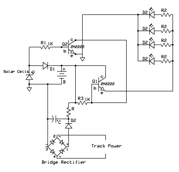
schematic_with_track_power.jpg 1
The bridge rectifier has 4 connections, two that normally connect to AC and two that output DC. Although we are not using AC on our trains we want to allow charging whether the trains are running forward or backward. The bridge rectifier does the trick as it takes either polarity from the track rails and guarantees that the right polarity goes to the circuit.
The diode keeps the battery from discharging through the track power end of the circuit. The capacitor is important if you are running a power supply that uses pulse width modulation rather than a continuously variable voltage. It smoothes out the pulses and lengthens the life of the rectifier and batteries. The value is not critical, anything over 1000 µF should do. Just make sure the voltage rating is well over your track voltage or you may have a loud BANG as the capacitor explodes! Even if your power supply is not using PWM the capacitor won’t hurt. The resistor, R4, limits the current being delivered to the batteries. Some experimentation may be needed here. I found that using a 200 ohm resistor (actually two 100 ohm, 1 watt resistors in series) for R4 limited the current going to my NiCad battery pack to 100 milliamps when I was running at top speed. I am comfortable with that charge rate as I rarely run trains at maximum and the resistor never got more than warm to the touch. If you run your trains for long periods of time it would be wise to either increase the resistance or include a switch so that track charging can be turned off. Rechargeable batteries do not react well to being overcharged!
Since there was no space on the circuit board for this addition I used what is fondly called “dead bug” construction where you simply solder the components onto each other with the leads looking like insect legs! Be sure to observe polarity on the Bridge rectifier. There is normally a single “+” sign on one terminal. That lead is positive, the lead opposite it is negative and the two to the sides are for the AC or, in our case, track power.
Capacitors usually have a stripe to indicate the negative terminal. The two resistors in series can be seen to the left of the diode and capacitor. I simply connected the output from the circuit to the bottom of the board where the battery hooks up.
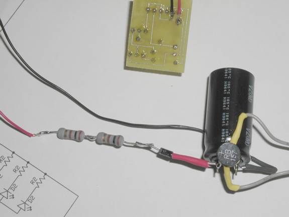
track_power1.jpg 1
Again, be careful to double check the circuit and test the current going to the battery before using this circuit modification.
Good luck and let me know how this works for you!