
Turnout Motor
Control
revised 11-15-06
Model railroad turnouts, often called switches, can be controlled in a number of ways. The most basic is a manual control that is thrown by hand. Remote activation is usually accomplished by either pneumatic (air) or electrical means.
The project that is the focus of these articles has several turnouts that must be remotely activated by a microcontroller. As mentioned in the last article the output power available on a PICAXE is quite limited, certainly nowhere near what is required to throw a turnout. I have seen many turnout motors drawing nearly 2 amps when activated so some sort of intermediate device, like the transistor that was used with the relays, is needed.
Before we can choose the appropriate device to operate the turnout we need to examine how turnout motors operate. The two most common electrically operated turnout motors utilized in garden railways are those made by LGB (item number 12010)...
and those made by AristoCraft (11299).
 O
O
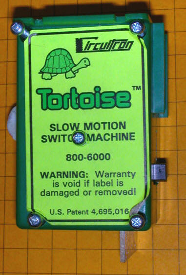
We will also examine a slightly less common unit from Circuitron called the slow motion Tortoise. Although not designed specifically for garden railway use it can easily be attached to most turnouts. In the photo below the five screws that hold the sides of its case together have been partially removed. Oops - guess I voided the warranty!
All three of the turnout motors operate in much the same way. Power goes to each turnout motor through two wires. When power is applied in one direction, that is the positive connection goes to one terminal while the negative goes to the other, the turnout is turned one way. When the polarity is reversed the turnout is activated in the other direction.
Even though these devices operate in similar ways their internal makeup differs significantly.
Inside of the AristoCraft Turnout Motor
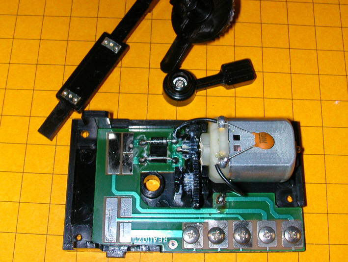
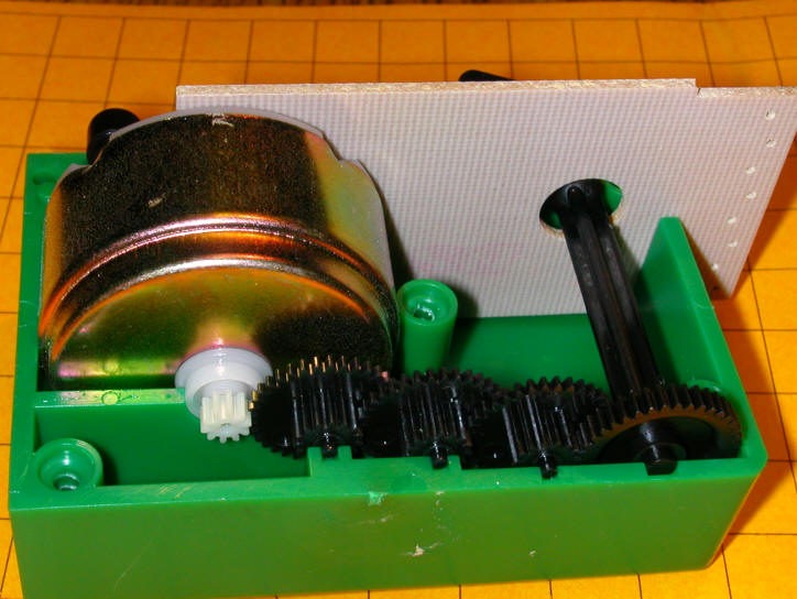
The design of the AristoCraft 11299 utilizes a small DC motor to throw the turnout. The small motor's power is multiplied by a set of gears. The most unique characteristic of the AristoCraft units is the inclusion of a set of contacts and a pair of diodes that completely disconnects the motor from power once the turnout has been thrown. This means that the motor draws virtually no power once it is thrown and the power can be left on indefinitely.
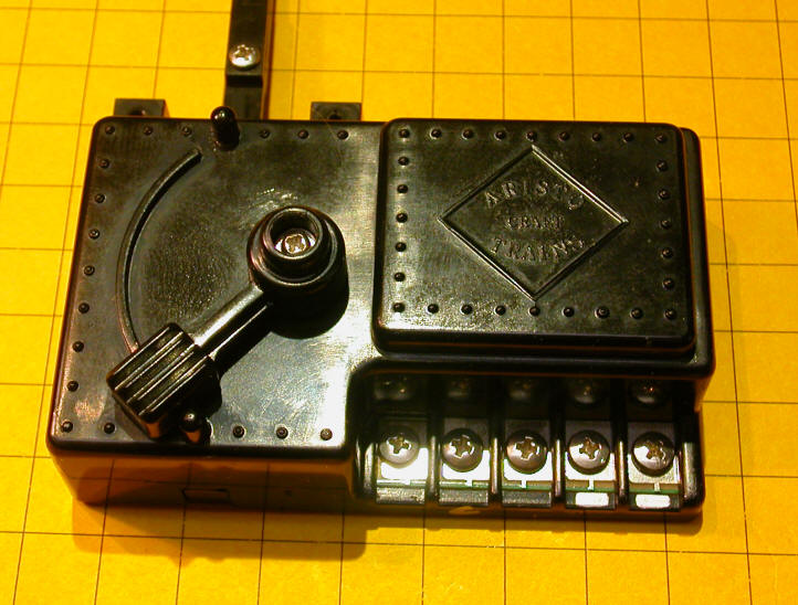
In the first photo you can clearly see the motor in the upper right corner and the gears that connect it to the arm that moves the turnout.
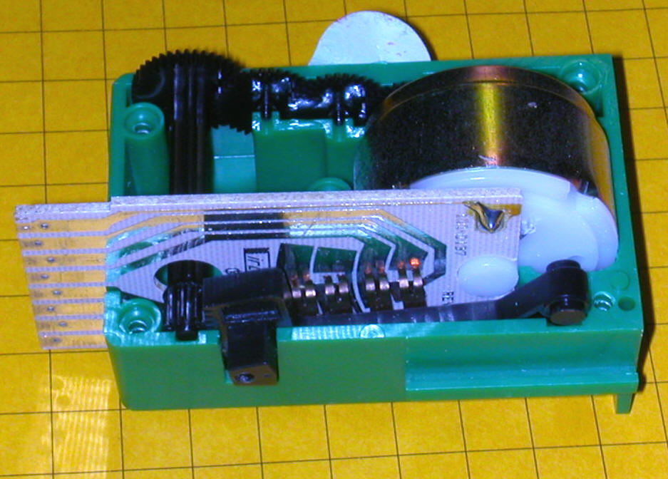
In the second photo the arm has been removed and turned over. The contacts on the bottom of the arm slide along the metal traces on the circuit board to disconnect the power from the motor once the turnout is fully thrown. The two diodes, just to the left of the motor gears, reenergize the motor when the polarity of the DC power is switched.
The contacts also give you access to a SPDT switch that can be used to activate other turnouts, lights or accessories.
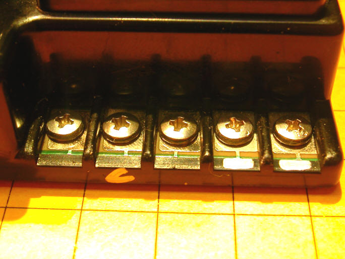
This close-up view shows the five contact screws. The two on the right are used to power the turnout motor. The three on the left make up the SPDT switch contacts with the center screw, marked "C", being the common terminal. In the photo above you can follow the traces inside of the motor and see where they go.
Inside of the LGB Turnout Motor
LGB 's 12010 utilizes more of a rotating solenoid actuator rather than a normal motor. When power is applied in one direction a permanent magnet rotates inside of a coil of wire throwing the control arm in one direction. When the polarity is reversed it rotates in the opposite direction, throwing the control arm the other way. If power is left on the turnout motor will continue to draw current and will heat up. This does not seem to do any damage and only wastes power.
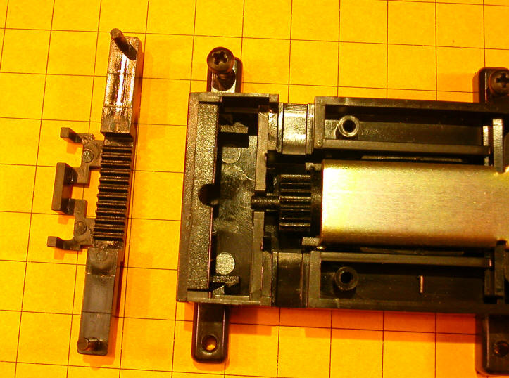
In this view the motor's top has been removed and the movable arm has been flipped over to show the rack that is normally across the gear to its right.
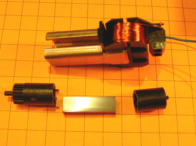
Here the motor has been completely disassembled revealing the coil and the iron core that goes through it. Below the coil is the permanent magnet that normally sits between the sides of the iron core. The plastic pieces next to the magnet encase it and hold it centered in the unit.
The LGB unit does not normally have switch contacts available but there is an add-on DPDT switch module (12070) that can be hooked to the end of the switch motor.
Inside of the Tortoise Turnout Motor
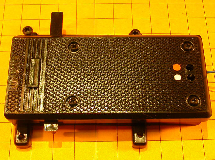
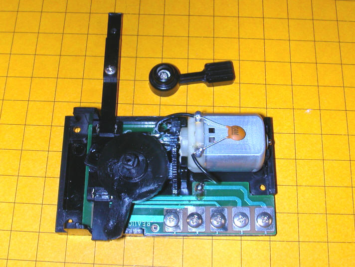
When the tortoise's cover is removed you can see the motor to the right, its gear train, a set of contacts and the arm that moves to throw the turnout.
The extensive gear train can be seen here. It allows the motor to exert a great deal of force without drawing much power.
The Circuitron Tortoise's motor is like the AristoCraft's but it does not disconnect itself from power once the control arm moves. It simply stalls and continues to draw power as long as the circuit is complete. Again, this seems to be part of the design and appears to do no harm. The most significant difference between the operation of this turnout motor and the others is that it operates at a very slow rate, taking as long as a few seconds to completely move the control arm. The others snap one way or the other in an instant.
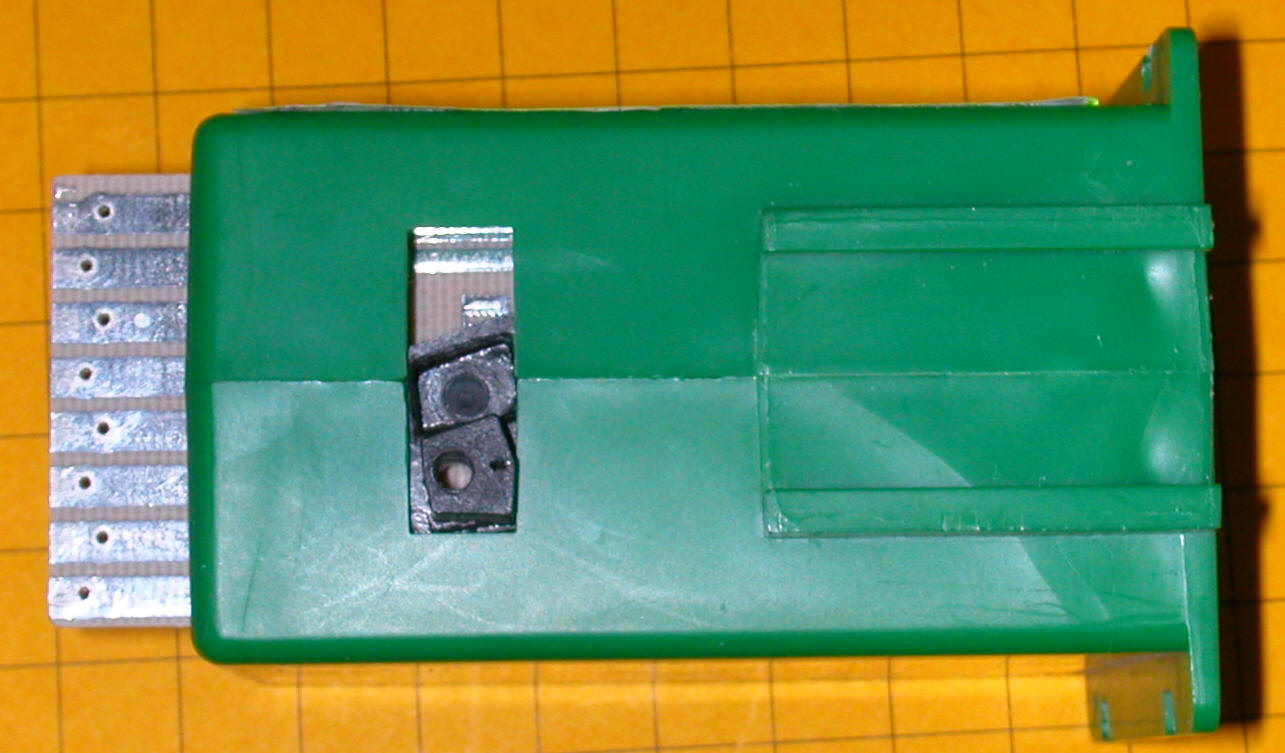
Power is connected to the top and bottom contacts that are on the left in the photo below. The other six contacts make up a DPDT switch that can be used to activate other things. The moving arm that activates the turnout is the black object in the slot. It moves slowly from one end of the slot to the other when power is applied with its direction of travel determined by the DC's polarity.
AC or DC?
Even though the manuals for both LGB and AristoCraft call for AC to be connected to their turnout controllers the AC is converted to half wave DC by a diode before it is sent off to the turnout. I have done extensive tests with both brands of turnout motors and they work very well on pure DC and have suffered no ill effects after thousands of activations.
Operation with Relays
It appears, then, that two things need to be provided for in order to operate turnout motors. First the turnout’s direction is determined by setting DC polarity. Next a short pulse of DC needs to be sent to the turnout motor.
One solution is to use a double pole, double throw (DPDT) relay to set the polarity. Once polarity is established a second relay, a single throw (SPST), is used to briefly send power to the turnout motor as shown in the diagram below. You could, of course, use a DPDT switch and a pushbutton switch to replace the relays. In this example we are using relays to meet our objective of allowing a microcontroller to operate things.
Let's Go Solid-State
Even though relays would work well in this application I prefer to use purely electronic circuits that have no moving parts to wear out. There is a perfect substitute for both the DPDT relay that reverses polarity and the SPST relay that activates the relay. In fact there is a single 16 pin integrated circuit that does both and will control not just one, but two turnout motors! That is significant when you realize that all of the circuitry above is necessary to control just one turnout motor.
The device I am going to employ is an H-Bridge. These integrated circuits are made up of a number of transistors and other components that create the electronic equivalent of a double pole, double throw switch. I described the use of an H-Bridge in the first article I wrote for LSOL, Robot Trains in the Garden. In that article the IC is used for its more traditional purpose, operating a motor. When connected to a DC motor it can regulate both speed and direction.
One Amazing Little Chip
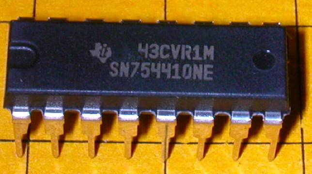
The Texas Instruments SN754410NE is an amazing chip. Inside of its 16 pin enclosure are housed two complete, independent H-Bridge controllers. Please note that the schematic below identifies the device as an LM293D. That is the device I used at first but it is only able to handle ½ amp on each of its H-Bridge sections. The SN75440NE is a direct replacement that can handle twice the load, a full amp on each bridge.
The schematic below shows the H-Bridge connected to two turnout motors, a source of +5 volts and a source of +12 volts. Both voltages are needed since the chip's logic circuitry uses 5 volts while the switch motors require 12.
To activate a turnout motor the two wires labeled "Motor Direction" need to be set so that one is connected to +5 volts and the other to ground. This sets the direction for the turnout. Once that is done connecting "Motor 1 On/Off" or "Motor 2 On/Off" to +5 volts will activate the motor. Switching the "Motor Direction" connections so that the wire that was connected to +5 goes to ground and the one that was to ground goes to +5 volts will cause the motor to reverse when either "Motor 1 On/Off" or "Motor 2 On/Off" is connected to +5 volts.
To experiment with the H-Bridge install it on a solderless breadboard as shown in this photograph. 12 volts enters through the two alligator clips in the upper left corner. This is dropped to 5 volts by the 7805 voltage regulator in the lower left. Note that all of the red wires carry 12 volts and the orange ones carry 5 volts. An AristoCraft switch motor is on the right. All of the connections are made as in the schematic above except for the ones on the schematic's right which are for a second switch motor.
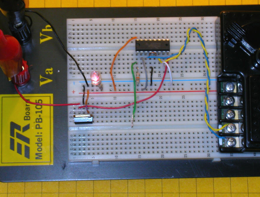
We are only going to use one of the H-Bridges on the chip. Connect the two wires from the turnout motor to pins 3 and 6. In the schematic these pins connect to the Motor symbol. In the photo they are blue and yellow. Connect pins 4 and 5 to ground, the negative terminal of your power supply. Connect pin 16 to a source of 5 volts and pin 8 to 12 volts. Pin 16 supplies voltage for the chip’s internal circuitry while pin 8 connects to the power for the turnout motor.
Pins 2 and 7 determine the polarity of the voltage that will go to the turnout motor. It is important that one of these pins always go to ground while the other goes to +5 volts.
If you look carefully you will see in the close-up below that there is a resistor that goes from pin 1 to ground. That is so that the activation pin is always held "low" when it is not connected. Without the resistor the switch motor could be activated prematurely. Note that the green wire that goes to pin 1 is not connected, it is just hanging in the air.
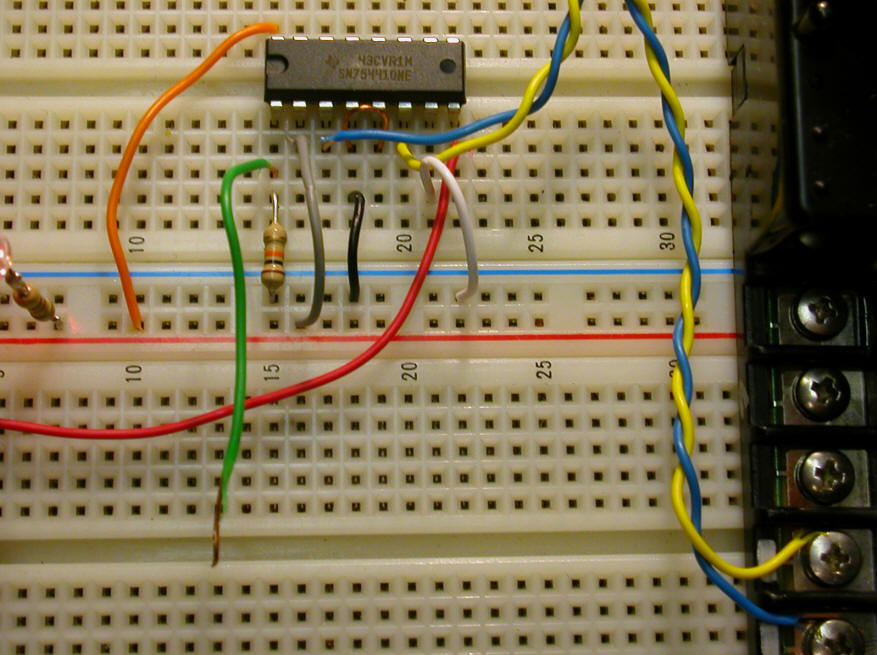
With the pins connected as described briefly touch pin 1 (the enable pin) to +5 volts. If the turnout doesn’t throw remove power from pin 1 and manually move the turnout motor in the other direction and try again. The turnout should activate and change its direction. Keeping pin 1 disconnected switch pins 2 and 7 (grey wire to negative and white wire to positive) so that the one that went to plus now goes to minus and visa versa. Again briefly touch pin 1 to + 5 volts. The turnout will again activate, this time in the opposite direction.
This video shows the steps described above in action.
<LONGER VIDEO OF SWITCHING WIRES>
Rather than manually switching wires we can hand this task over to a PICAXE microcontroller. You should be able to see how the microcontroller can easily toggle pins 2 and 7 to change direction and activate the motor with pin 1.
In this photo the grey, white and green control wires have been connected to a PICAXE 08M. You will also note that the resistor that was used with pin 1 on the H-Bridge has been removed as it is no longer needed. A small filter capacitor, the orange object just right of center, has been added to keep voltage fluctuations from the switch motor from resetting the PICAXE.
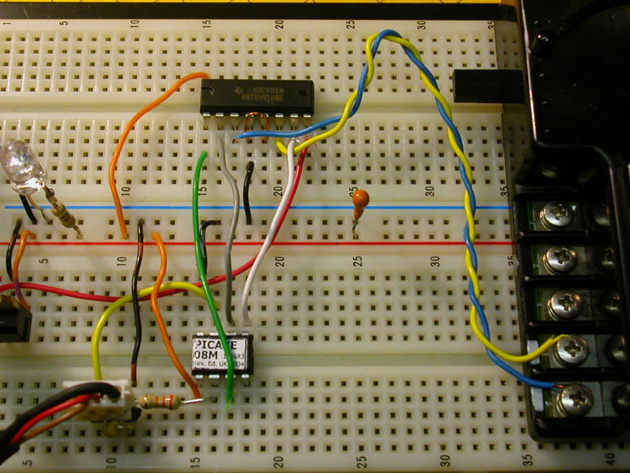
A very simple program sets one of the direction wires high while the other is set low. Then pin 1 on the H-bridge is activated for a moment to throw the switch motor. The direction pins are reversed every second and the switch motor goes back and forth under computer control!
<NOTE TO JON- Please make sure the program below is sized so that each line does not wrap - THANKS!>
| 'PICAXE TEST PROGRAM
High 1 'grey wire
to +5 volts |
<SHORT VIDEO OF PICAXE THROWING SWITCH MOTOR>
If you are experimenting with an LGB or AristoCraft switch motor you will discover that you only need to activate the motor for 1/10 second or so to move the motor's control arm. If you are working with the slow motion Circuitron unit you need to keep the unit activated for a second or more to move the whole way from one extreme to the other. Such changes are a snap when a PICAXE is running the show!
To Be Continued...
In the last installment we learned how to electronically control blocks. Now we can add to our toolkit the ability to throw switch motors. Our next topic will involve a simple solution to the problem of controlling a train's speed as it enters a block. Stay tuned!