Give Your Engines the "Capacity" to Ignore Dirty Track
revised 11-20-07
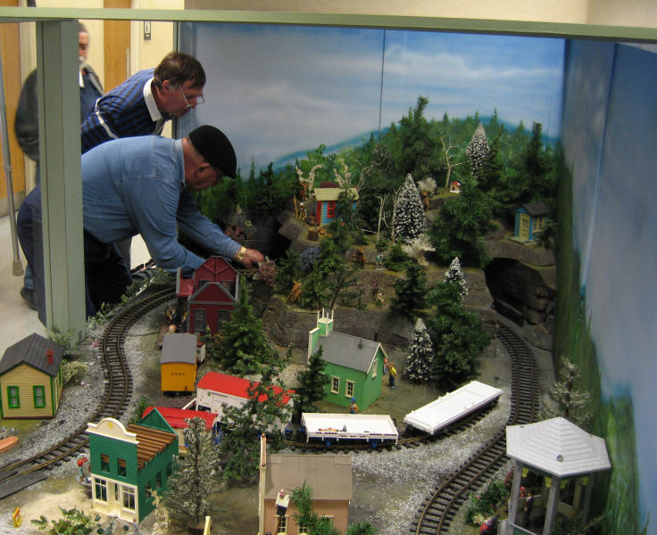
A few months I was given the opportunity to help maintain the Pittsburgh Garden Railway Society's model train layout at Pittsburgh's Children's Hospital. This layout, which depicts the day the circus came to town, has been in continuous operation for more than seven years and is a favorite with the children and staff. When fellow PGRS member Bob Groover and I first saw the layout we were very impressed with its design and operation. Human nature being what it is, however, it wasn't long until we began discussing things that might be changed to make it even more appealing to the children.
My first thought was to have the circus train start out and stop more gradually. In its current configuration there are two buttons that start the train, one four or so feet above the ground for adults and one closer to the floor for children. The buttons activate a timer that turns on the AC power to the transformer for 50 seconds. When that time has elapsed power is abruptly removed and the train stops. As you can imagine the starts and stops are sudden and somewhat jarring to the eye and to the equipment!

Being something of an electronic tinkerer my first idea was to build up a microprocessor based unit that would use PWM (Pulse Width Modulation) to accelerate the train gradually, let it run for some time less the timer's setting and decelerate to a stop before power was removed. A workable solution but not necessarily a good one. My main concern was that it would be adding a complex device that might fail and bring the layout to a halt. The more complex a system becomes the more likely there is going to be a problem.
What I wanted was a more passive device that would do the same thing as the electronic circuit. This got me to thinking about what happens when you turn off a large table radio, TV or stereo system. Such devices, especially older ones using tubes, generally go on playing for a second or two before becoming silent. I knew that this was caused by the device's internal capacitors keeping things alive for a short time as they discharged. Such behavior is more than just a curiosity as it seemed to have potential for solving the train problem since we were looking for something to keep the train running for a second or two after the power was removed.
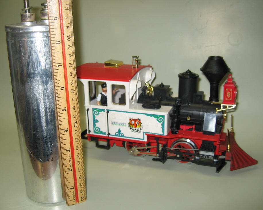
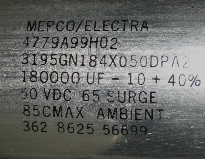
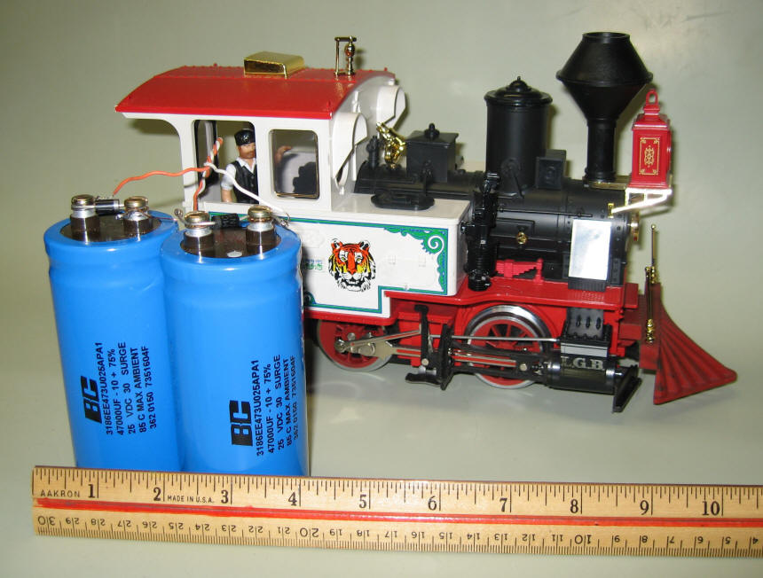
I spent some time doing research on the Internet and discussing my thoughts with some real electronic experts, fellow ham radio operators, that I chat with frequently on the radio. The consensus was that a large capacitor, something in the neighborhood of 100,000 microfarads or more, should do the trick. One of these hams had a very large capacitor that he gave me for experimentation. When I say large, I mean VERY LARGE. It was rated at 180,000 microfarads at 50 volts and was 9 inches tall and almost 3 inches in diameter. In the photo below it dwarfs an LGB 0-4-0.
ONE CAPACITOR CIRCUIT
The circuit needed to utilize the capacitor couldn't have been simpler. All that I had to do was to put the capacitor in parallel with the track power, being sure to observe proper polarity since this was a polarized electrolytic capacitor. When the power was turned on the train delayed for an instant as the capacitor charged. More importantly, when the power was suddenly removed the train continued to operate for several seconds as the fully charged capacitor slowly discharged. The end result was a much more smoothly running train that stopped very realistically. The acceleration vs. deceleration times were not symmetrical, that is the train started out more quickly than it stopped, but it was a vast improvement.
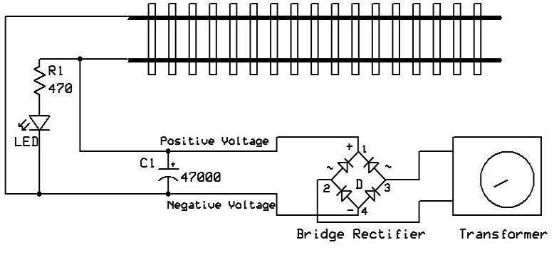
In the schematic below there are two components in addition to the capacitor, C1. They are an LED and a current limiting resistor. I included them for two reasons. First they give a visual indication that the capacitor has been charged as the LED will be illuminated only when the capacitor holds a charge. More importantly, the LED and resistor will slowly discharge the capacitor should there be no train on the tracks. As you will see later on in the article a large charged capacitor is not something to leave laying around!
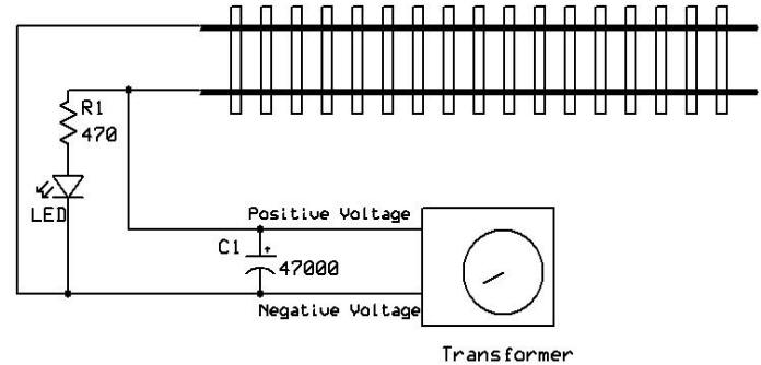
The circuit above works, but there is a problem with this solution. Did you notice my comment in the paragraph above about observing proper polarity? As Hamlet once lamented "Ah, there is the rub!" Since the type of capacitor that I was working with was a polarized device, with a + and a - terminal, the train could only be run in one direction and the polarity could never be reversed as reversing the polarity to run it backwards would reverse charge the capacitor with potentially disastrous (as in explosive!) results. The good news is that our layout only runs in one direction and there is generally no need to reverse the train. The problem would only come up should we have to back the engine out of the tunnel.
ONE CAPACITOR CIRCUIT WITH A BRIDGE RECTIFIER
One solution that I came up with was to place a bridge rectifier between the transformer and the capacitor. You may recall that a bridge rectifier is a four pin device made up of four discrete diodes that are configured in such a way that a positive and negative voltage are always available on the same two output pins no matter what the polarity of the voltage (even AC) that goes into the input pins. Just make sure that you use a bridge rectifier with a high enough current rating to handle the current draw of your engine. Two or three amps should be more than sufficient for most applications. Note that the train cannot be reversed when this circuit is used. No matter what direction you set the transformer for the train will always go in the same direction. (For more information on bridge rectifiers see my article "5 Volt Power for Railway Electronics")
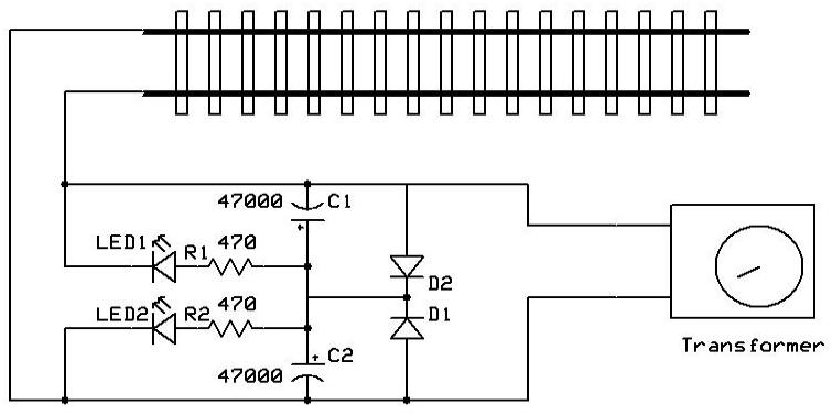
TWO CAPACITOR CIRCUIT
Even though the bridge rectifier solution was fine for the Children's Hospital application I still was interested in a circuit that would moderate acceleration and deceleration no matter which direction the train was running. So I was back to the drawing boards and to my ham radio comrades for more research. It turns out that there was a simple solution. If two polarized electrolytic capacitors are wired " back-to-back" with two diodes you wind up with a non-polarized capacitor, that is one that doesn't care about polarity. It works perfectly in this application. The train started and stopped just as it did in the first application whether running forward or backward.
You will note that an additional LED and current limiting resistor have been added so that a visual indication of charge is available for each of the capacitors.
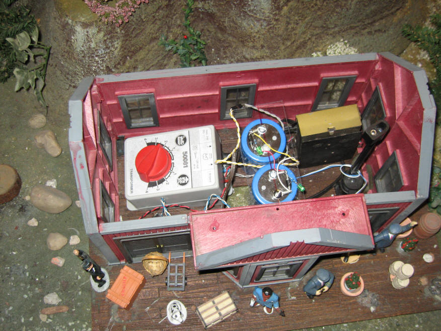
The photo below is of the two capacitors installed inside of a building at Children's Hospital.
This is a great solution for the Children's Hospital layout and for a point-to-point trolley layout, but it also has the potential to alleviate one of the major problems that those of us who use track power run into frequently: dirty track stops trains!
IGNORING DIRTY TRACK!
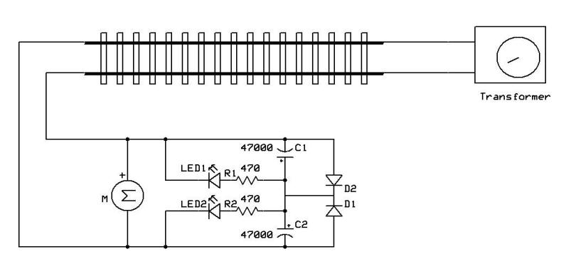
In order to use the power that is stored in the capacitors to glide over sections of dirty track all that needs to be done is to mount the capacitors and diodes on the train rather than trackside with the transformer as I did with the hospital layout. As you can see from the schematic below the only difference is that the capacitors, diodes, LEDs and resistors are beyond the engine's motor, either in the engine or a trailing car, not trackside with the transformer.
THE QUEST FOR SMALLER CAPACITORS
I am sure that you have noticed one major problem with installing two capacitors and diodes onboard an engine. Even though our trains are called Large Scale, they aren't quite large enough to accommodate two of the capacitors the size of the ones in the photos above. The specifications for the very large capacitor are 180,000 microfarads at 50 volts. Both of those characteristics effect a capacitor's size. Experimentation proved that the acceleration / deceleration effect was still noticeable and worthwhile even if the rating of the capacitor was as low as 30,000 microfarads. The voltage rating needs to be no more than something above our maximum working voltage. Since your power supplies don't put out much more than 22 volts a 25 volt rating should be sufficient.
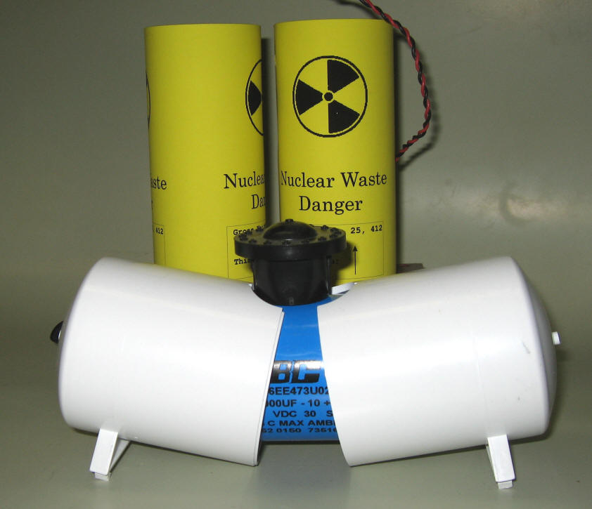
A bit more research located an ideal capacitor, 47,000 microfarads at 25 volts, 30 volts surge. The physical size is much more acceptable, a little over 4" high and about 2" in diameter. Even though they might not fit inside of too many engines they are easy to conceal inside of a trailing car. Please note that in the photo below the diodes have been installed but not the LEDs and current limiting resistors.
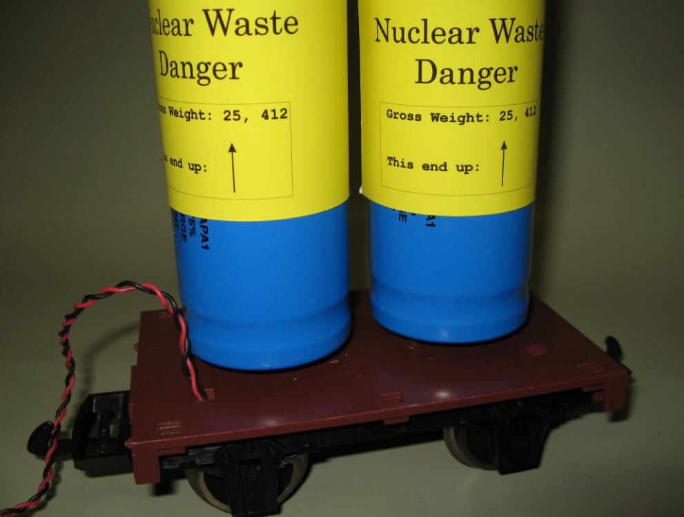
There are any number of different ways to conceal the capacitors. One method that I utilized was to mount them both vertically on a small Hartland ore or tank car base. A quick cover, disguising them as nuclear waste containers, was made up on the computer.
![]()
As you can see the capacitors were mounted upside down on the car.
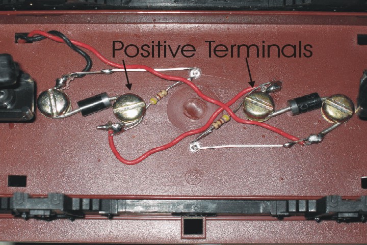
The two screws on the top served double duty as connection terminals and mounting screws when I drilled holes in the base. The two diodes, resistors and LEDs are clearly visible in the photo below.
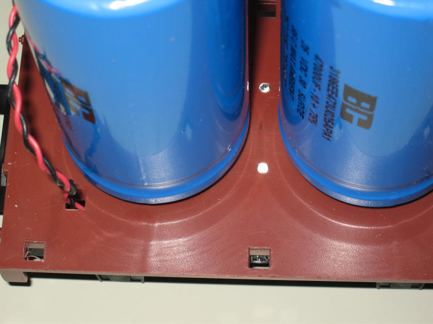
The LEDs are mounted in holes so that they can be seen from the top of the car.
Both capacitors can easily fit into just about any boxcar, caboose or tender. They might even fit inside of a diesel locomotive. Another option is to put the capacitors into the cavity inside of two Hartland tank cars. One capacitor fits perfectly inside of each one! Wires would need to be run between cars to connect them but they are easily concealed as well.
Connecting it to an engine is simply a matter of bringing out two wires that connect to the engine's power terminals. Make sure that you don't try to use these capacitors with an engine that has DCC or other sophisticated electronics. It is safest to stick to simple engines that have little, if any, internal circuitry other than track power pickups and a motor.
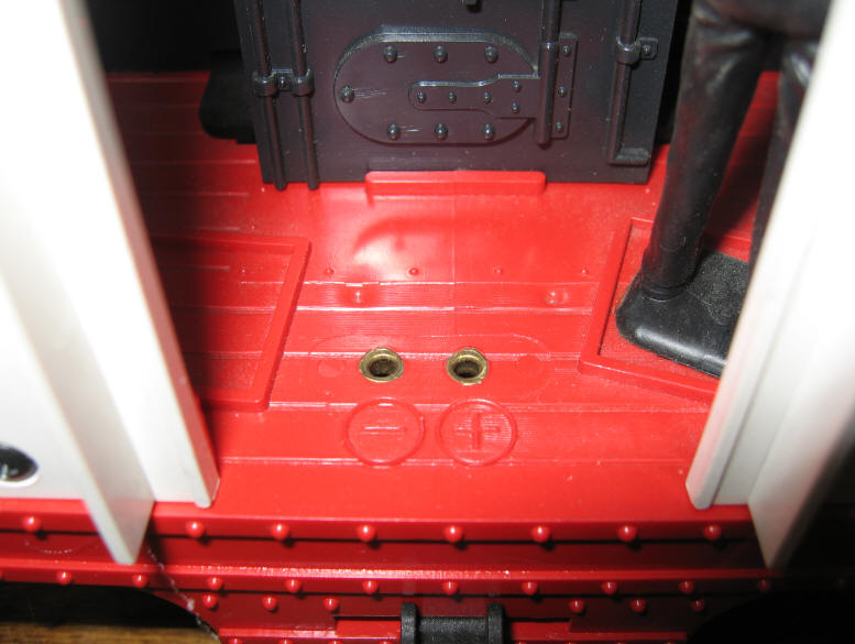
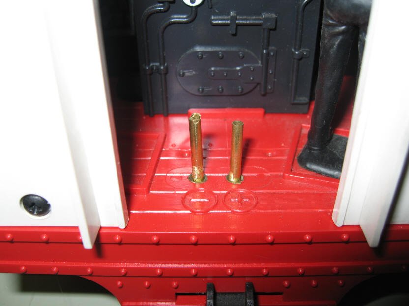
Many LGB engines, such as the small 0-4-0 that is pictured above, have power takeoff connections in them. In the photo below they are in the cab and are marked + and -.
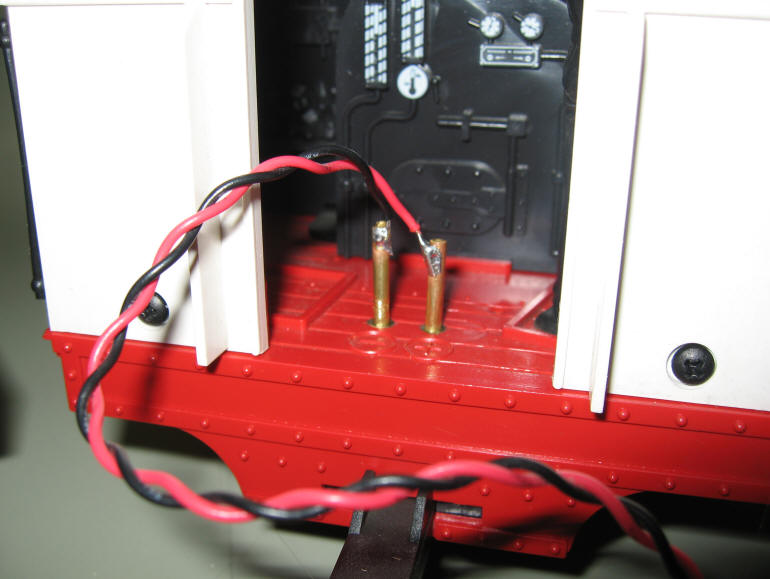
I didn't have any connectors that would plug right in but found that a few pieces of 3/32" brass tubing fit well if they were tapered a bit on one end.
The soldered wires go directly to the capacitors on the trailing car. Just make sure that both LEDs on the capacitors are out before plugging them in as there is a chance that you could short them together and generate some big sparks.
With the setup above the capacitors take over as soon as the engine hits a break in the track, as sometimes happens over switches or a dirty area. As long as the interruption is less than a few feet the capacitors do a super job. A track cleaning engine is an ideal candidate for this modification as nothing is more frustrating than needing to clean the track before you can run a track powered track cleaning car or engine but it won't run properly until the track is clean. A classic "Catch 22!"
| It is important to give a few more words of caution about working with large capacitors like the ones described in this article. Capacitors have the potential to store a great deal of energy and to release it all in an instant. For example, I have seen situations where a screwdriver shorted out the terminals of a large fully charged capacitor and its tip was literally burned off. Needless to say you must to use caution when working with these devices. Always assume that they are fully charged and prevent their terminals and the wires connecting to them from shorting. The LEDs will go a long way towards making sure that this is not a problem. Just make sure that they are both out before doing any work on the system. |
A FINAL ISSUE RESOLVED
As I worked on this article and experimented with the capacitors there was one aspect of the circuit's operation that never completely satisfied me. The capacitors did a super job of decelerating the engines when the power was removed taking a few seconds to discharge and gradually bring the train to a complete stop. Unfortunately, the capacitors charged so quickly when the power was first applied that there was only a barely noticeable acceleration delay at the start. It does keep the wheels from spinning but the train still starts out too quickly for my tastes.
I found a nearly perfect solution that I will discuss in detail in a coming article. It involves another simple device that is commonly used in a television or other electronic device. Stay tuned for more...
GIVE IT A TRY!
If you share my interest in tinkering with electronics and garden trains give this a try and let me know how it works for you!
If you would like to experiment with this idea I have a few of the 47,000 microfarad / 25 volt capacitors on hand. The cost is $5.00 each + shipping. Please contact me at dave@davebodnar.com if you are interested.