Constructing with Rigid Foam
revised 4-19-06
Over the last few years I have experimented with a number of different methods of constructing buildings, walls and other structures for my garden railroad. I have found that many materials that are supposed to be water resistant and able to tolerate direct contact with the ground have a short lifetime when exposed to Pittsburgh's weather extremes.
I built several structures using Hardiboard and found that they don't hold up well when used for a building floor or for walls that might touch damp earth directly. I am not sure if it is just the constant dampness or the freeze / thaw cycle that destroys it but I have been disappointed with its performance.
I also built a number of retaining walls & building foundations using JigStones. While the stones themselves held up well I have found that most glues, including exterior Liquid Nails, are good for no more than 2 years of constant ground contact. After that the glue softens and the walls fall apart.
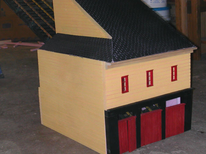
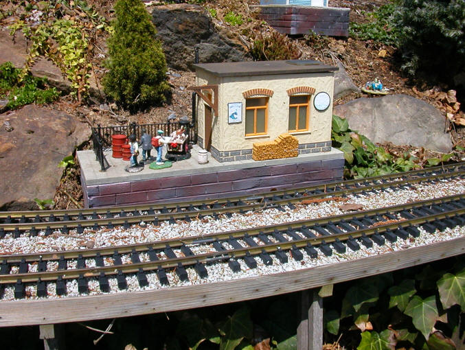
The station that accompanied the incline that I wrote about a few months ago (see: http://www.largescaleonline.com/members/emag/article_485.html ) was made from what is fast becoming my favorite construction material, rigid foam insulation. That station was made of foam that was partially covered with a thin layer of concrete to provide texture. Since then I have been adding texture directly to the foam and have been pleased with the results. The second incline station, pictured below, is also made from foam. The horizontal lines that make the buildings siding and the shingles on the roof are "burned" directly into the foam before painting.
I have not had any foam structures out in the weather for more than a few months but hope that it will hold up at least as well as other exterior materials. In this article I would like to present some of the things I have found working with this material along with some other ideas for building construction that you might be able to use.
Types of Foam
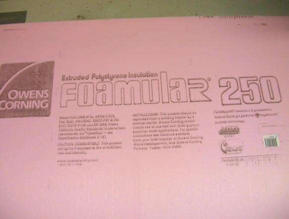
There are a number of rigid foam products that you can find at home centers. The product that I have been working with is available at our local Home Depot and is called Foamular and is made by Owens Corning (see: http://www.owenscorning.com/around/insulation/products/foamular.asp ). It is pink in color and comes in 4' x 8' sheets in a number of thicknesses including: 1/2", 3/4" and 1". The cost ranges from a bit under $10 per sheet for the 1/2" to around $15 for the 1". There are other foam insulation products in other colors and I would think they behave similarly.
Do not try to use the white foam insulation that you may come across. It is generally sold in 4' long sheets that are wide enough to fit between wall studs, not in 4' x 8' sheets. If you look closely you will see that it is made up of thousands of small balls of Styrofoam that have been loosely bonded together. Not only is this foam insulation much weaker than the rigid foam but it makes a mess when you try to cut it as the individual balls of foam tend to separate and go everywhere!
Advantages / Disadvantages of Rigid Foam
There are a number of reasons that I have chosen to work with rigid foam insulation:
Cost: The cost per square foot for 1/2" thick insulation about 25 cents. There aren't too many other building materials that come at such a reasonable price!
Moisture resistance: This product is designed for and frequently used to insulate concrete house foundations where it is glued to the foundation before being backfilled with soil. We can't ask for much more!
Cutting: Foam insulation can be cut with a utility knife and a straight edge. You can also use hand tools such as saws, files and rasps as well as power tools like table saws and band saws.
Adding texture: textures that simulate concrete, stone and wood can easily be added
Painting: latex paints work well and come in thousands of colors
There are a few things on the minus side, too:
Strength: if you have a medium or large dog who loves to romp through your layout foam structures can easily be damaged. While it is sturdy any direct impact has the potential to dent or chip the foam.
Weight: Structures must be weighted down if used outside or the wind is sure to carry them away. A large foam building can easily weigh less than one pound!
Dissolves: most spray paints and lacquers cannot be used with rigid foam as the solvents used in them will dissolve the surface of the foam. That said, careful application of such products can add interesting textures! You must also take care to use glues that will not dissolve the foam. Experimenting on scrap is the best test.
Flammable: Rigid foam is much more flammable than wood and many other materials that we use for buildings. Avoid using it near any area that might have an open flame or high temperature such as a barbecue or garden candle.
Thickness: If you are making detail items from foam the thinnest sheets that are commonly available are 1/2" thick. This may be too thick for what you want to do. I have resawed foam on my band saw to create 1/4" sheeting but it becomes very weak at that thickness.
Cutting Foam Insulation
I generally use a utility knife to cut the 4' x 8' sheets of foam into three pieces at the home center as they are easier to transport inside of the car rather than on its roof. Once at home I carefully square up the rough cut edge with a long metal straightedge and a utility knife.
If I need a number of pieces that are the same size I typically set up a fence on my table saw or band saw. Either will easily cut the foam board. One word of caution for those of you who might be using a table saw. I have noticed that the sheets can easily bind between the fence and blade if you don't keep them 100% square causing kickback. Don't be fooled by the ease of cutting, a table saw is still a very serious tool and has the potential to inflict severe injuries if it grabs and throws the foam!
A metal framing square comes in very handy when using a utility knife to cut smaller pieces. I find that making two or more passes with the blade is best.
Joining Foam Pieces
I have used a number of different glue products to join foam, including various white glues and construction adhesives. All work well but the one that I like best and use the most is generic hot melt glue. It holds well and dries in a short time.
Experiment a bit with your hot melt glue and gun. I have found that mine, an old Craftsman unit, puts out glue that is hot enough to melt the foam so I need to keep the bead of glue back at least 1/4" from the finished edge to avoid having squeezed out glue leave a melted area in the foam.
I have also found that the glue sets much more slowly when used on foam than on other materials. I would think that this is because the foam, being an insulator, keeps the glue hot longer. This is a good thing as it allows you time to work the position of the pieces before the glue sets.
Every Building Needs a Firm Foundation
As a starting point let's look at making a simple building foundation. In the last week I have made nearly a dozen of these to place under my buildings. As you look at the photos of my layout here and on my web page (http://davebodnar.com/railway/) you will note that there is not a single bit of completely flat terrain to be found! Every building is either on the high or low side of a hill. To facilitate keeping everything in place and on the level I decided that a foundation for each building would be ideal.
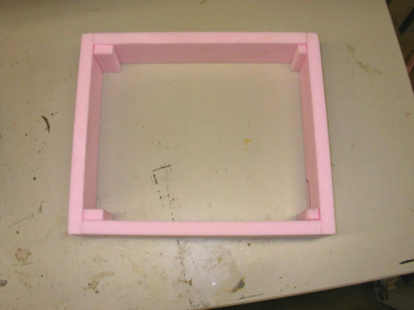
For buildings that are on a gradual slope a rectangular foundation made up of four pieces of foam is all that is needed. I generally make the sides of the foundations 3 or 4 inches high so that a good bit of the foundation can be buried, improving its rigidity. In this case I want to build a 3" high foundation that is for a building that is 12" x 14" in size. If 3/4" foam is used we will need two pieces 3" x 12" and two pieces 3" x 12 1/2". Note that the missing 1 1/2" for the 14" size will be made up by the thickness of the two pieces of 3/4" thick board.
Be careful to make the sides parallel and the ends square. I used a table saw, rip fence and miter gauge just as I would had I been making something from wood. Dry fit the pieces together before gluing.
Put a small bead of hot melt glue on the first edge to be joined and hold the pieces together for a minute of so as it cools. Continue with the other corners until you have a rectangular box. Reinforce the inside of each corner by gluing a small block of foam to it.
Adding Mortar Joints
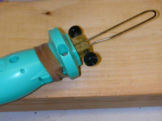
Once the foundation is done it is time to make it look a bit more like it was made out of concrete block or stone. There are many tools that can be used to add lines (mortar joints) and texture to the foam. I picked up a simple tool at the last National Convention that does a nice job. It is called Tippi and can be ordered from http://www.bigcityhobbies.com/order.htm for under $50.00.
The Tippi tool is just a handle attached to a stiff piece of resistance wire. When it is plugged in it heats up to a temperature that will melt the foam.
Note the rubber band in the photo below. It holds the Tippi's push button on/off switch in the on position so you don't have to constantly wait while it reheats.
You can use it, along with a straight edge, to mark the horizontal and vertical mortar lines that we want on our walls, but I have found it to be tedious to make dozens of evenly spaced lines with it as you must take the time to mark the foam for each cut.
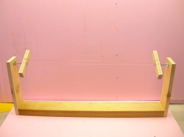
I have come up with what I think is a better method that I really speeds things up. All that is needed is a simple wood frame to hold a piece of nichrome wire (resistance wire like what is used in a toaster), a power supply to heat it up and a second piece of non-heated wire to act as a measuring guide.
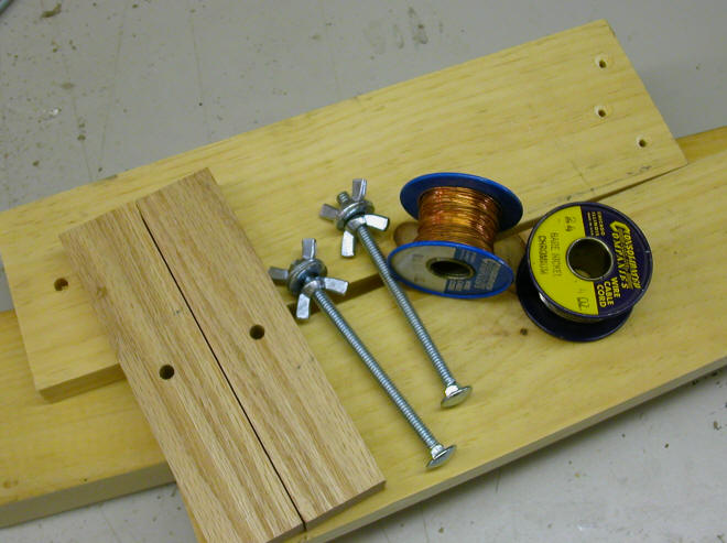
Here is what you need to make it. Please note that none of these measurements are critical. Please adjust them to fit the size of foam that you are working with. The dimensions here allow for some very large structures.
30" piece of 2" x 4" for the base
2 @ 1" x 4" x 8" for the sides of the frame
2 @ 1" x 1" x 8" for the wire holders - these should be a hard wood, like oak
2 @ 1/4" x 4" carriage bolts
4 @ wing nuts to fit carriage bolts
4 @ washers to fit carriage bolts
36" piece of 24 to 30 gauge nichrome wire (if you don't have access to nichrome wire drop me an email and I'll be glad to send along a piece for what it costs me)
36" piece of 24 gauge copper or steel wire
train transformer (I used an old Lionel unit) or 6 volt - 12 volt @ 1 amp wall wart power supply from junk box - note that the thinner the nichrome wire the higher the voltage you will need to use as the wire's resistance increases as its diameter decreases
2 @ medium size alligator clips from junk box or Radio Shack
1. Drill a centered 1/4" hole 1" down from the top of each of the side boards.
2. Securely attach the two sides pieces to the 2" x 4" board. I used 3 long dry wall screws on each side.
3. Drill a 1/4" hole in the center of each of the wire holders
4. Cut two thin slots on either side of the hole in the wire holder so that they are 1" apart (later on you may want to add additional slots for different spacing between the hot nichrome wire and the cold copper wire)
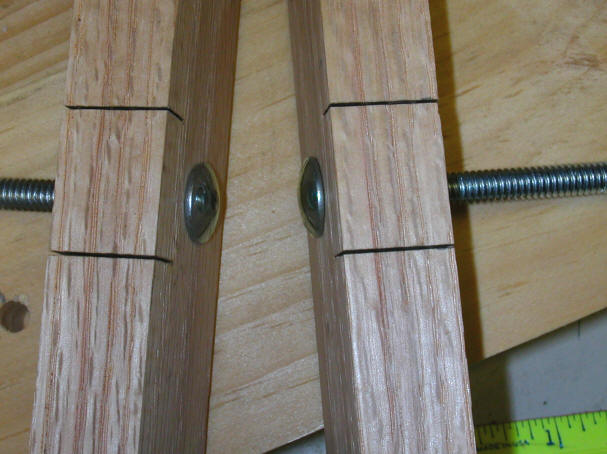
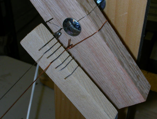
5. Insert a carriage bolt into each of the wire holders and hammer it into the wood so that it will not spin (carriage bolts have a square protrusion under the head for this purpose)
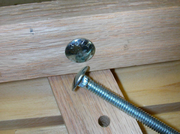
6. Put a wing nut and washer on the carriage bolt, insert it into the side piece and add another washer and wing nut. Note the position of the wing nuts.
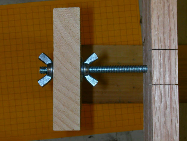
7. Adjust the bolts and nuts so that very little of the bolt goes through the side pieces. This will allow room to put tension on the wire when it is attached.
8. Stretch the nichrome wire between the slots on the wire holders. Wrap the wire around the holder securing it tightly.
9. Similarly stretch the other piece of wire between the other two slots. Note that the two pieces of wire must not touch or the current will go through the lower resistance copper and the nichrome wire will never heat.
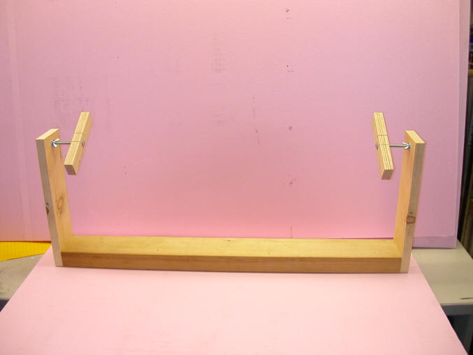
Here is the completed jig ready to be electrified.
10. Solder or screw the alligator clips to the two wires from your power supply.
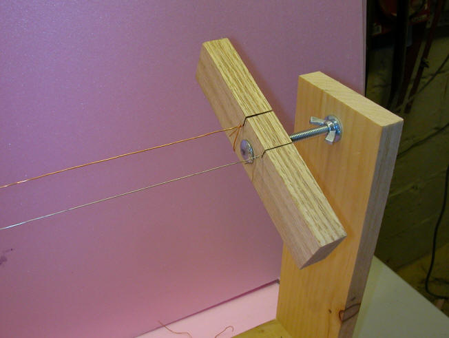
11. Adjust the wing nuts so that the two pieces of wire are spaced evenly and stretched tightly. Lock the wing nuts so that the blocks supporting the wire can't move.
12. Clip an alligator clip to each end of the nichrome wire
Once the unit is complete it is time to apply power. I had the best luck with an old Lionel transformer from the late 1940's. They deliver up to 15 volts AC at several amps. The 24 gauge nichrome wire heated nicely with the throttle in the middle of its travel. A volt meter showed that it was delivering about 9.5 volts to the nichrome wire. Remember that thinner nichrome wire will require a higher voltage to heat to the same temperature as its resistance is higher. If you use heavy gauge nichrome you may need to drop the voltage to just a few volts.
![]()
Here are the characteristics of the three different sizes of nichrome wire that I worked with. The transformer pictured above worked well with all three sizes. Simply adjust the speed control until the wire is just hot enough to mark the foam.
| Gauge | Ohms / foot | Suggested voltage for 24” length |
| 24 | 2.2 | 9 |
| 28 | 4.7 | 12 |
| 30 | 7.4 | 15 |
Once you identify a good working voltage you can try a fixed voltage power supply, like an all wall wart, that supplies the voltage you are using at least 1 or 2 amps. Remember that the nichrome wire will heat properly from an AC or a DC supply.
I am sure that you will soon discover that this unit will easily cut right through the pink foam. It can be used for this purpose but my main objective is to remove the tedium associated with making any number of parallel lines in foam to simulate mortar joints, wood siding or shingles.
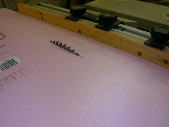
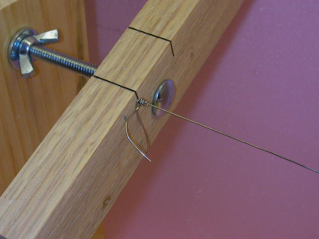
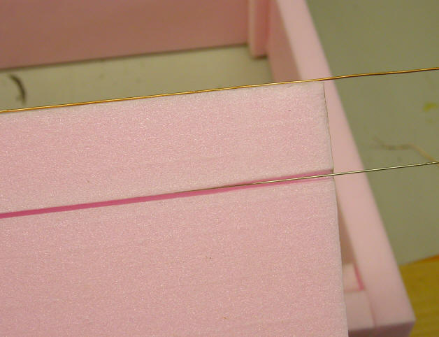
The first step in making these markings is to decide how far apart they should be. For the foundation I am simulating large stones so the horizontal mortar joints are going to be 1" apart. If you wanted to make smaller blocks all that you need to do is to cut another notch in the wire holder to move the wires together. I have also had good luck by inserting small slotted blocks between the wires to pull them closer together as pictured below. Just loosen the tension, insert the blocks at each end and tighten up the wire again.
Before heating up the wire practice holding the foam as described below. You may also need to adjust the angle of the hot and cold wires by rotating the supports depending on the size of your foam structure.
Heat up the nichrome wire and hold the edge of the foam foundation against the cold wire as you rotate the face of the foam into the hot wire.
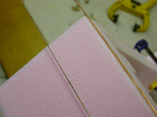
Allow the wire to penetrate the foam to a depth of 1/8" or so. Go deeper if you want more pronounced joints.
Pull the foam back from the hot wire and put the slot that you just cut onto the cold copper wire.
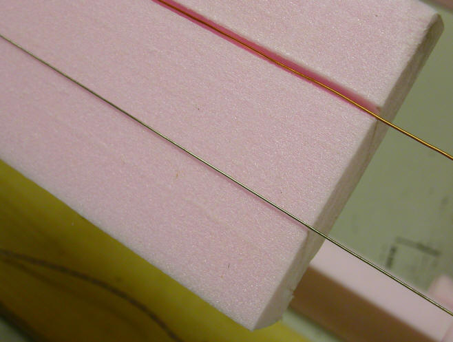
Continue down and then around the foundation. When you are finished you should have evenly spaced horizontal mortar lines all the way around the foundation.
Vertical Mortar Joints
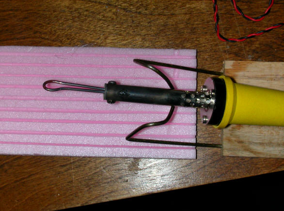
The Tippi does a good job of making the vertical mortar joints. Simply press the heated tip of the wire into the foam to the same depth that was cut for the horizontal lines.
An old fine tipped soldering iron can also be used to make the vertical mortar joints. The one that is pictured here has a removable tip. I found that replacing the original tip with a doubled over length of #14 copper wire did a good job on the foam. If the tip is too hot just use a longer piece of wire as the additional length will dissipate much of the heat before it gets to the end of the wire.
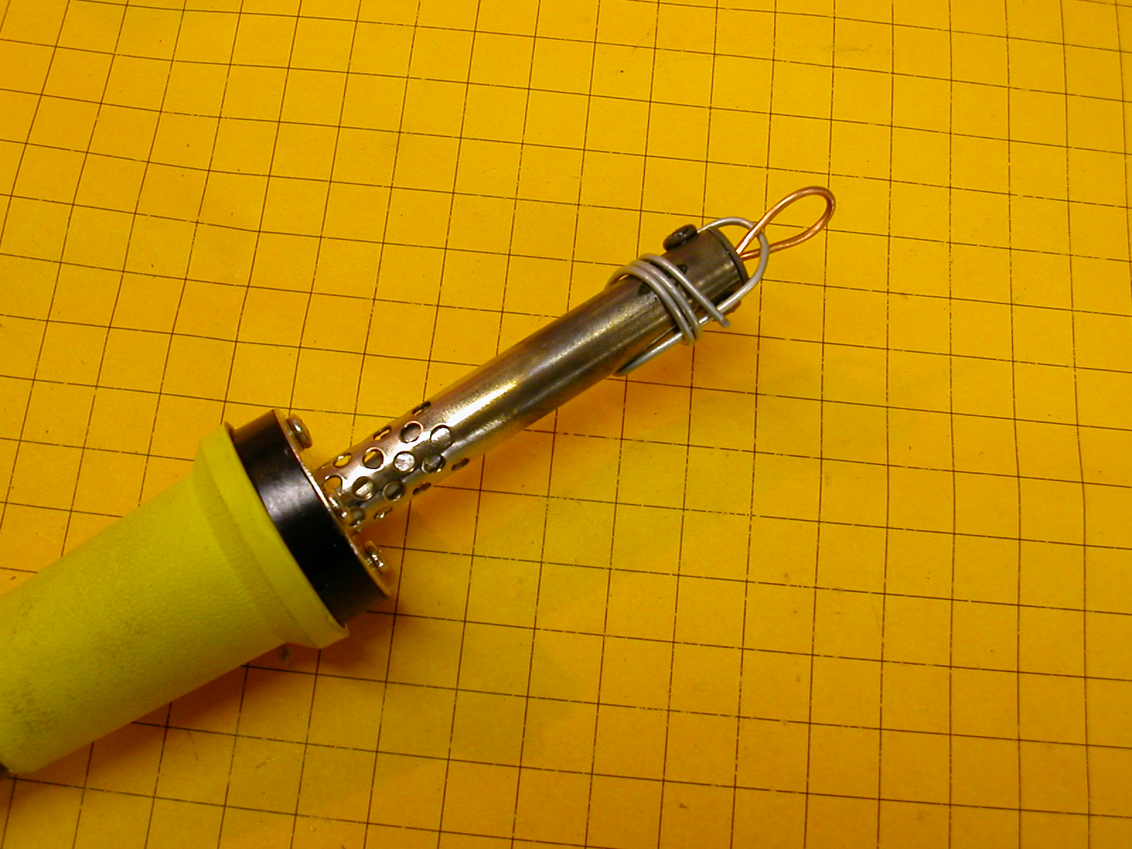
If your tip is not removable you can just wrap the copper wire tightly around the body and tip. More than enough heat will transfer to the wire to successfully mark the foam.
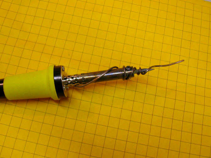
Here an even thinner piece of copper wire is being used. Note the heavier piece of wire that holds it in place.
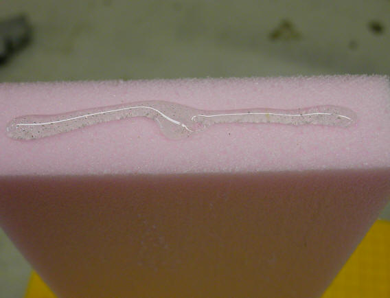
In the sample below horizontal lines were cut about 1/4" apart and the vertical lines were done with the modified soldering iron. To give grey mortar lines I first sprayed the foam with grey auto primer. This was a Rustoleum product that does not seem to attack and dissolve the foam.
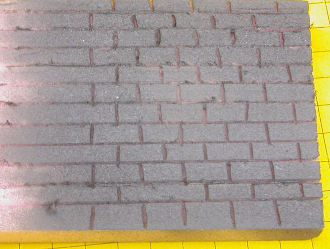
After the grey paint dried I used a scrap of foam to apply a red latex paint to give a brick appearance.
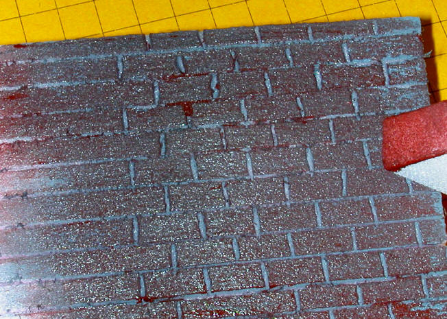
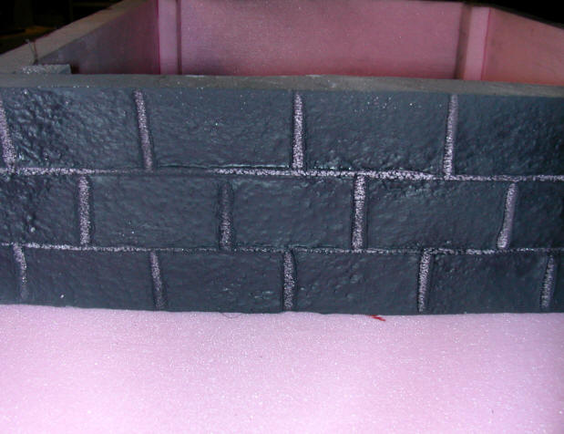
In the photo below the foundation is shown with its vertical mortar joints after it was sprayed with black primer. Even though this is also a Rustoleum product it did attack and start to melt the foam. In this case it gave an interesting texture much like concrete block.
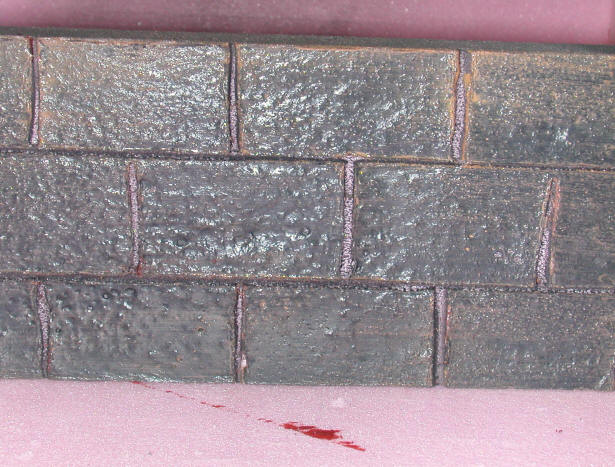
Here is the same piece after it was heated briefly with a hot air gun. It melted the surface of the foam a bit again giving an interesting texture. I have also done this with a propane torch but it is much more difficult to use as you can easily destroy the foam's surface to say nothing of starting it on fire!
I am sure that those of you with more artistic ability than me can come up with more paint and texture ideas to make realistic brick, block and stone walls. I can also point you in the direction of a real expert who has been sharing his building construction techniques for years. Lawrence "Yogi" Wallace has a multitude of great ideas for using foam on his web page at: http://users.stratuswave.net/~wd8jik/foamcutter/foamcutter.htm You will also note that Yogi uses blue rigid foam rather than the pink that I employ. He reports that it has some interesting characteristics that give more textures to explore.
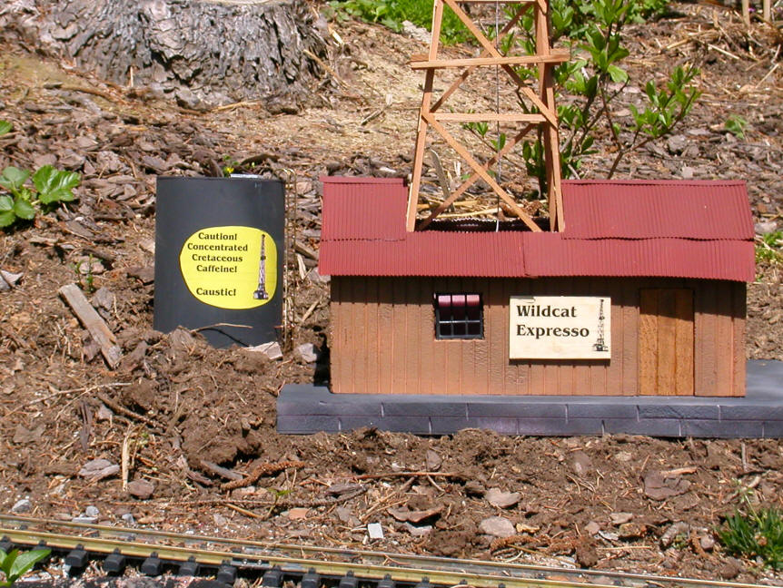
You've Never Seen a Expresso Well?
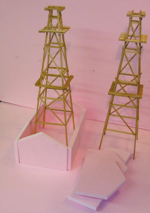
I have mentioned before that my railroad's main purpose is to transport prehistoric coffee beans from the Cretaceous Coffee Mine to the Wizard's Cup Coffee Refinery. A new development has crews working furiously to complete a number of wildcat expresso wells as there is evidence that there is concentrated liquid coffee underground as well. I needed to build shacks to accompany the drilling derricks and figured foam was the way to go. (note that the wells are for "expresso" not the more common and mundane "espresso". The "X" is for the fact that drinking it is still experimental!)
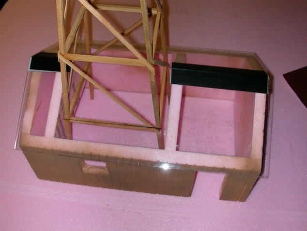
In the photo below are two of the drilling derricks and the pieces of pink foam that will make up the ends and the sides of the two drilling shacks. The derricks are just made up of sticks of cedar that I milled on my band saw. The side pieces for the shack were cut on my table saw with the blade adjusted to the same 30 degree angle that was used to cut the end pieces where they support the roof.
I had good luck simulating horizontal wood clapboard siding with the yellow incline building and thought I would use a combination of both horizontal and vertical wood planks on these buildings. All that I had to do was to adjust the spacing between the cold and hot wire to about 1/2".
Before marking the planking I used a utility knife to cut out the door and window holes. The doors are just made up of pieces of rough cut cedar. The windows come from recycling old plant flats that my wife brings home every spring from the local nursery. The black plastic is strong, flexible and holds up well outside. A variety of different sized windows can be cut from one flat.
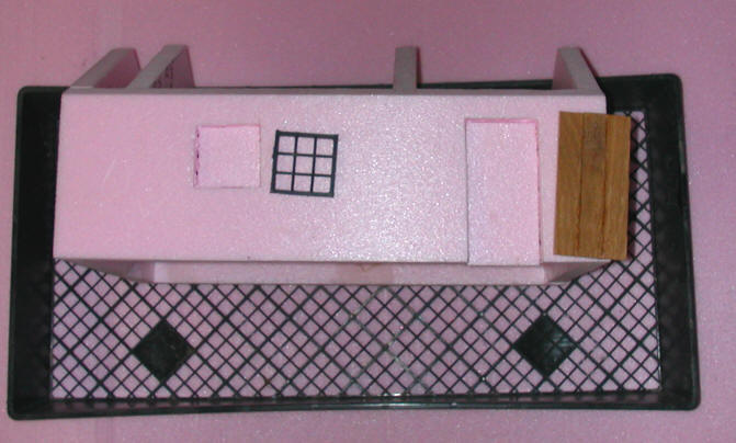
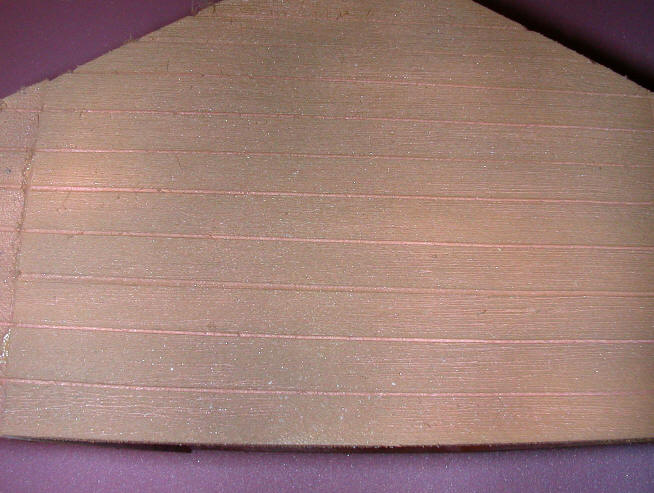
The sides of the shacks use vertical lines and the ends horizontal. After marking the horizontal and vertical plank lines distress the foam with a small wire brush. Pull it along the foam with the lines so that the scratches it leaves simulate wood grain. You can even add knots by poking small holes in the foam with the end of a hot nail or soldering iron.
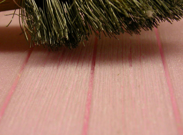
A quick coat of brown spray paint really brings out the "wood" grain! The paint dissolved the foam just enough to make the individual boards more interesting.
The roof employs another trick that I learned from Yogi. For details on making corrugated roofing from old pop cans see:
http://users.stratuswave.net/~wd8jik/rrib/rrib.htm The sections of roofing are run through a device called a "Fiskar's Paper Crimper" that I purchased a few years ago at Michaels Craft Store.
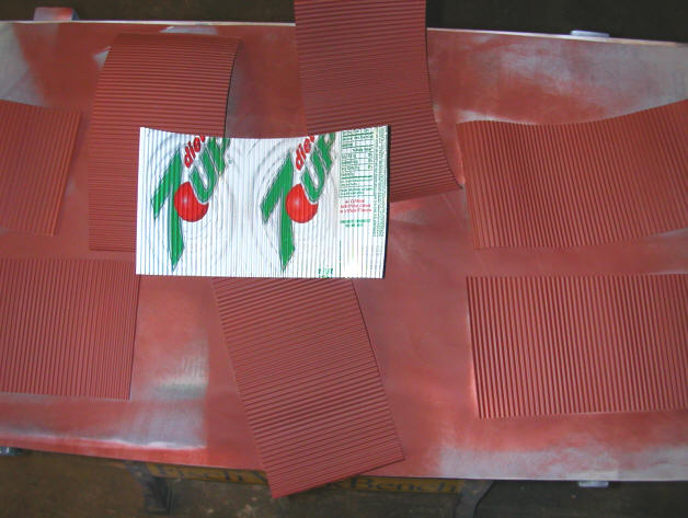
The corrugated cans are very thin and unlikely to hold up well as a roof. To make the structure stronger the metal is glued to thin sheets of Plexiglas.
Here 1/2 of the roof has been covered with the corrugated metal panels
.JPG)
More strips of metal from pop cans are used for the roof's ridge.
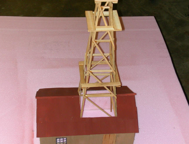
Here the finished building awaits a tank for the pumped coffee, a few signs, a proper foundation and a place in the yard.
.JPG)
Tank Construction
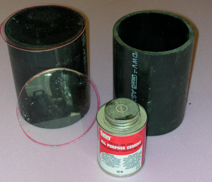
The tanks for the drilling operation are made from 6" high sections of 4" plastic pipe topped off with circles of thin Plexiglas. I cut the tops a bit larger than needed then trimmed them to fit with my stationary belt sander.
Ladder
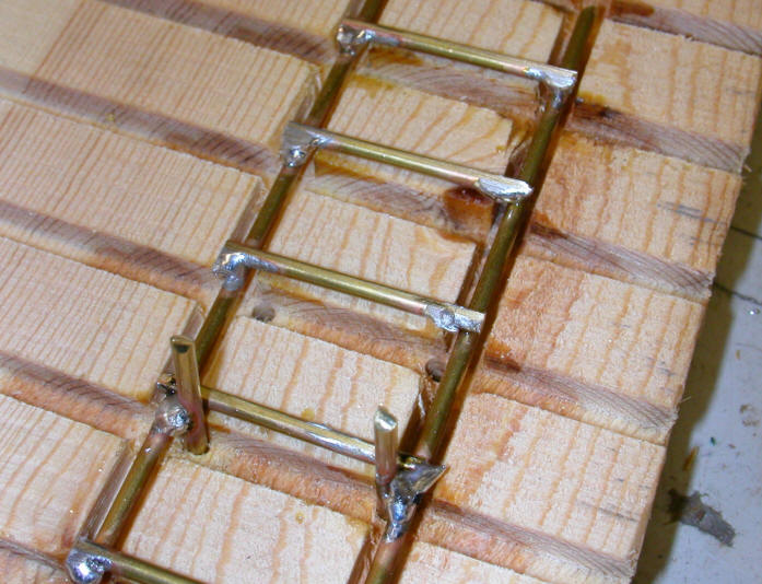
I have used a number of methods for making ladders and find that the following one is quick and works well. I made a jig by cutting slots in a board with my table saw. The blade is raised just 1/8" above the table and two long slots 3/4" apart are made. Then a dozen or so perpendicular slots are made 5/8" apart. These slots do a great job of holding the brass rod as I solder it together.
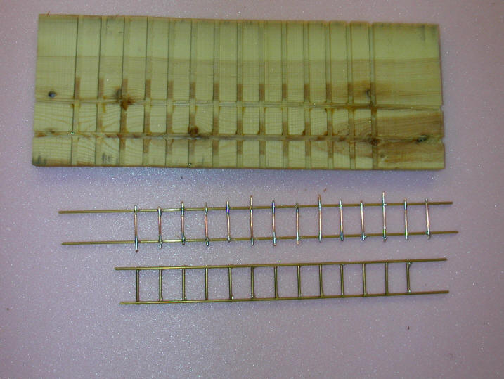
I have experimented with a number of metals and find that 1/16" or 3/32" brass rod works well for the vertical pieces and #14 copper electrical wire works best for the rungs. Clean all pieces thoroughly before cutting and cut the rungs wider than you need as seen below.
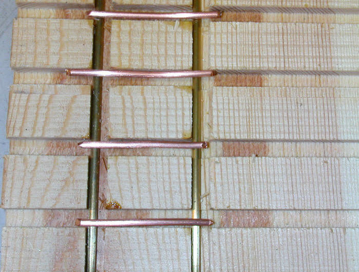
Keep a long nail or similar object handy to push the pieces into proper position as you solder. I intentionally made the saw slots larger than needed so that the ladder would release more easily from the jig and there would be room to work. Just keep pushing all rungs to either the top or bottom of their slots to maintain your spacing.
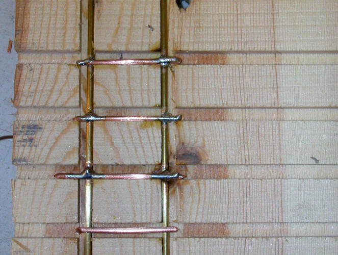
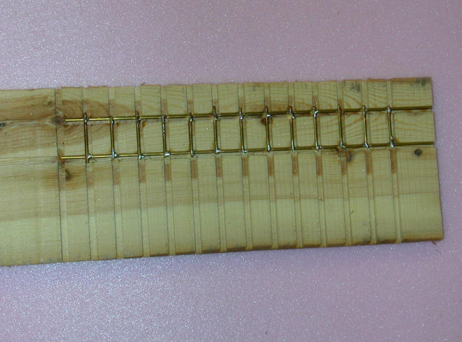
Here is a nearly completed ladder. A few seconds at the stationary belt sander will remove the sections of rungs that hang over the edges. Just don't heat them up so much on the sander that the solder melts!
Standoffs are held in place for soldering by pushing wire into a few holes strategically placed in the jig. Don't worry about excess solder as the side you are viewing is on the back of the ladder and the belt sander removes much of that.
The top of the ladder was bent to shape over a AA battery and inserted into holes in the top of the tank. The standoffs are also pushed into holds drilled in the tank's side.
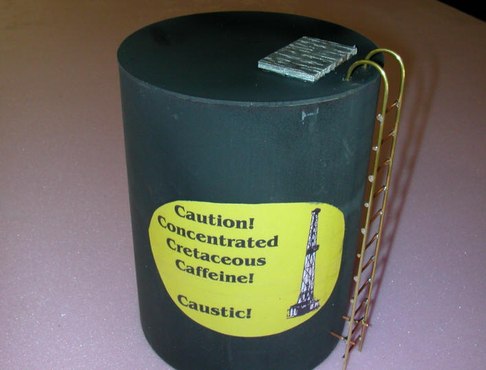
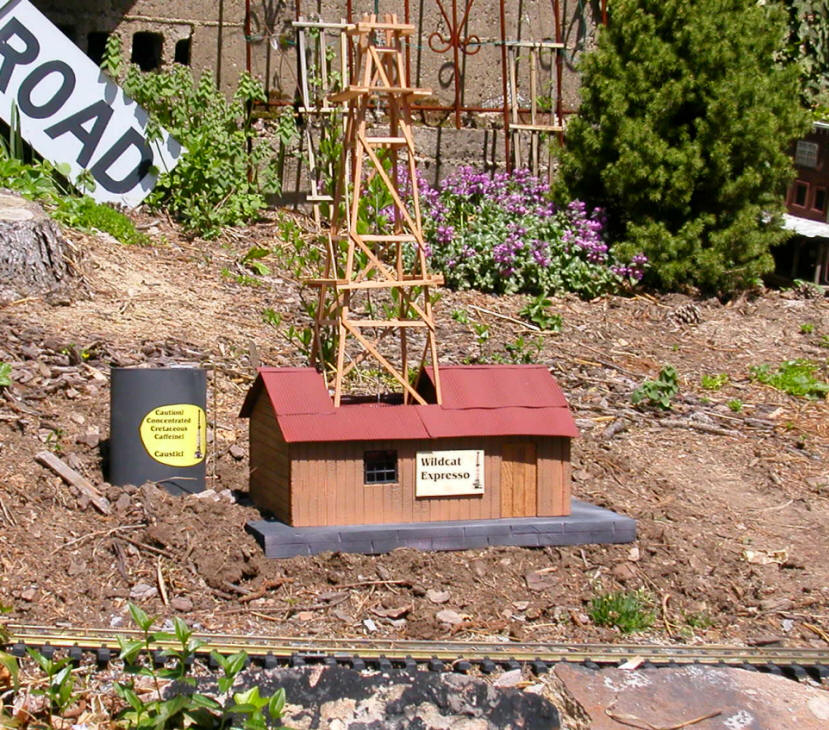
Here is one of the wells in place. A nice combination of foam, plastic pipe, Plexiglas, wood, corrugated pop cans and brass! I'll let you know how it holds up in a few years!