Give Your Railroad a Voice
Part II
revised 2-7-05 pm
DIGITALLY SYNTHESIZED vs. DIGITALLY RECORDED SOUNDS
In the first part of Give Your Railroad a Voice the focus was on boards that electronically generate wave forms that synthesize sound. This creates representations of sounds that are recognizable and appropriate for some uses. They are, however, no where near as realistic as those used on the more expensive chips that store and play back a digitized file of an actual recorded sound. This is the method employed by Phoenix and Sierra. These more sophisticated boards record and reproduce sound in the same manner as our computers, digital voice recorders and digital phone answering machines. That is, they continuously sample an analog stream of sound and convert it to a digital representation of that sound. On PCs they are normally stored as “.wav” or “.mp3” files. The quality of their audio output can be excellent and is determined by several things:
1. The quality of the microphone and circuitry that is used to record the sound.
2. The size and quality of the speaker and amplification circuitry.
3. The number of digital sound samples (called the sample rate) that are taken each second (As you can imagine, the more samples that are taken the better the sound will be but the more memory that will be needed to store them.)
4. The number of bits (or computer memory) used to record one sample (usually 8 or 16 – the higher the better)
There may be other considerations but these are the main ones. The sampling rate is usually the key to great sound. In order to get telephone quality sound you need about 11,000 samples per second, FM radio quality demands 22,000 and CD quality 44,000. We have all heard the result of high sampling rages and quality digital recordings when we listen to audio CDs on our home or car stereo system. We have also experienced the result of low sample rates when we hear the recorded messages on some answering machines, they can be choppy and high and low frequencies are frequently clipped.
The boards reviewed in this article use digital recording circuitry to record sound. They all contain a microphone, speaker, a recording switch and a play switch. Recorded sounds are stored in internal circuitry that retains the recorded sound even if the battery power is removed.
Finding Sounds
Because most of these boards do not come with any train related sounds prerecorded on them you will have to find sounds of your own to record for use on your railroad. Its fun to search for sounds for your railway and, as usual, Google comes to the rescue. Just search for “train sound wave files”. Here are some that I found:
http://www.grsites.com/sounds/trains001.shtml (24 train sounds)
http://simplythebest.net/sounds/WAV/sound_effects_WAV/transportation_wavs.html (3 files)
http://kickitup.railfan.net/html/mult/wave_misc_snds.html (at least 100 files)
You could also record sounds from other sources, just make sure that what you use is not a copyrighted sound. Sounds found on the web are frequently accompanied by a copyright or fair use notice that gives you permission to use them for non-commercial purposes. Please take the time to read and understand it before taking someone else’s work for your own use. If in doubt contact the person or company who made the sound or made the sound available.
Radio Shack Sound Recording Board
Radio Shack has sold a sound recording board (see: http://www.radioshack.com/product.asp?catalog%5Fname=CTLG&product%5Fid=276-1323 ) for some years. Jon DeKeles reviewed this unit (see: http://www.radioshack.com/product.asp?catalog%5Fname=CTLG&product%5Fid=276-1323 ) in April of 2004. I purchased one of these units around the same time and found that the playback was of very low quality and I returned it the same day. Those who developed this board used such a low sampling rate that the reproduction was severely distorted.
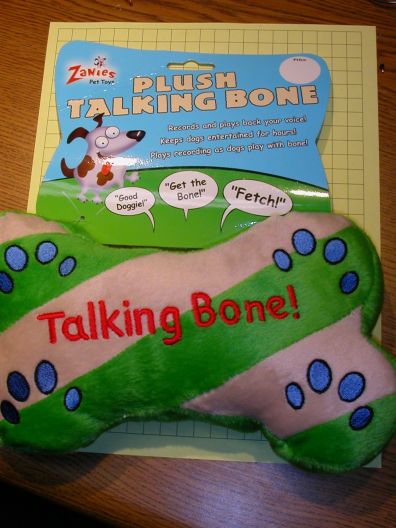
Dog Bone Sound Recorder
A few months ago I was looking over a pet supply catalog and found an intriguing item. It was a stuffed toy bone for dogs that contained a sound recording module that could record up to 10 seconds of your voice so that it would be replayed whenever the dog chewed the toy.
The price was reasonable so I ordered one for experimentation. When it arrived I didn’t hold much hope for its being better than the Radio Shack unit, especially with the small speaker that was inside. To say the least I was amazed by the reproduction quality that I experienced after recording a message. A quick exchange of speakers improved it even more. It was obvious that I has stumbled onto a unit that used a sufficiently high sampling rate to record what I have to believe is near FM radio quality sound.
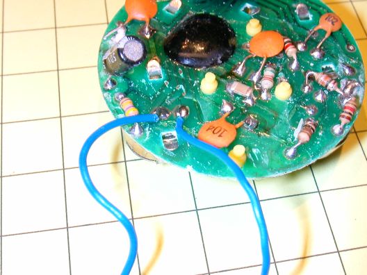
This picture shows the module that is inside of the bone. It can easily be removed from its Velcro secured compartment.
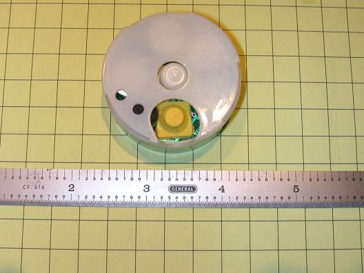
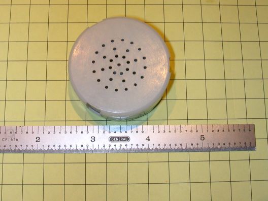
When the top of the nylon case is removed by releasing 3 clips the inside of the board is revealed. The white center button is pressed to play a recorded sound. The yellow button (which is normally recessed in the case) is held to record up to 10 seconds of sound. The small red LED (at the far right edge of the case) lights when you are recording and goes out when the 10 seconds capacity of the chip is used up. The four silver areas are holders for watch batteries.
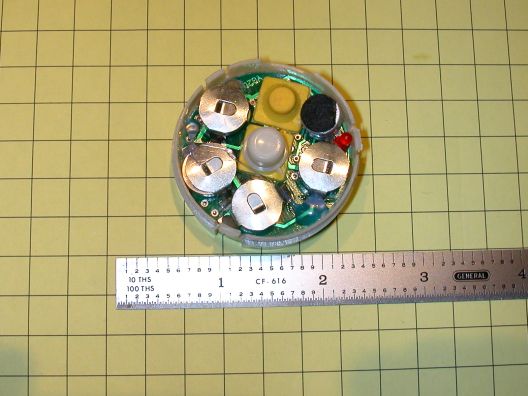
Removing a bit of hot melt glue releases the board and speaker.
The Talking Dog Bone is available for $5.99 from PetEdge.com
Because PetEdge is primarily a wholesale distributor they have a processing fee if your order is less than $50.00. If you or someone you know is a pet lover I am sure you can find many other things on their site to get to that order level.
The first thing you may want to do with this module is replace the small speaker with a larger one. I have experimented with a number of speakers from my junk box and have had good luck with all of the ones that have an 8 ohm impedance. This is the most common value for small speakers and most have their impedance marked on them. Although the audio output from this board is not extremely high, the volume increases a great deal when a 3 or 4 inch speaker is attached. This may be sufficient for some applications.
To replace the speaker remove the two blue speaker wires from the back of the board and replace them with the two wires from your larger speaker.
Installing an external switch to activate the recorded sound is the next step. The center button needs to be removed and replaced with two wires that run to your switch. To remove the button turn the board over and locate the four yellow rubber posts that protrude through the board. Push the two that are at the corners of the middle button through from the back. Leave the ones for the record button unless you want to make that an externally activated switch, too.
Once you remove the switch you will see a pair of interlocking copper traces that were under the switch. They look like two letter "E"s facing and intertwined with each other. A wire needs to be soldered to each of these traces and fed out to your external switch. In the photo below there is also a third wire, connected to the top of the right-most battery case, that is used for external power. Note that the batteries have also been removed as I intend to run this from external batteries.
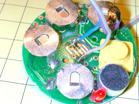
The three wires are ground, talk switch and positive power. The top wire (blue) is talk - touch it to ground to start talking. The bottom wire (light grey) is ground. The purple wire is positive voltage and is soldered to the top of the right battery holder.
To record a new recorded sound from your computer using the built in microphone, visible in the lower right of the photo above, simply place the microphone very close to your computer's speaker, hold the record button and play the sound. It helps to have three or four hands to do this, but with a little practice you should be able to coordinate starting the sound and pressing the record button so that just the right sound sequence is recorded. Remember to hold the record button until the sound stops or the red LED goes out.
If you would like to improve the quality of the recorded sound even more you can remove the microphone and connect wires directly to the computer's speaker output jack. Carefully heat the two leads from the microphone from the back of the board and lift it off. The two connections from the microphone are ground, the left contact in the photo below, and audio input, the right connection. You must reduce the sound level that comes from the computers speaker as it is much to strong for an input that is intended for a microphone. This is done by inserting a resistor in series with the audio input line. It can be seen in the photo. I found that a 10,000 ohm resistor worked well. If you find that the audio level is too high or low you can adjust the speaker volume control on the computer or substitute a larger or smaller resistor. Once the audio level is properly matched the recording will be free of extraneous sound that the microphone may have picked up.
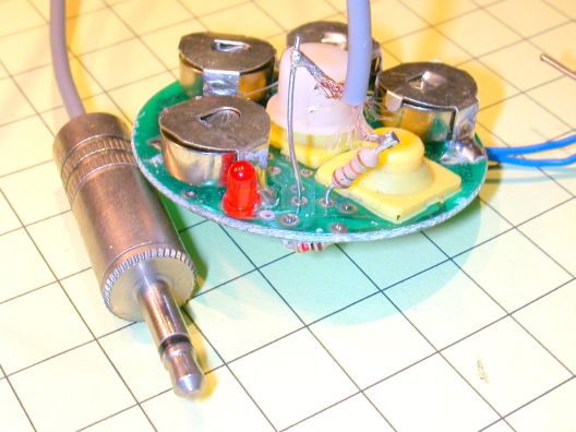
The last modification you may want to make is to replace the watch batteries that come with the board with a larger battery pack or a voltage regulator so that you can run it from track power. I have tested the board with external 6 volt batteries and with power from a 5 volt regulator and both work well. The circuitry to provide 5 volts from track power was covered in the first part of this article. If you want to use external power the positive lead should be soldered to the top of the battery case on the far right and the negative lead to the bottom contact for the battery on the far left. This negative contact is the same as the ground wire that is used for the talk switch as shown earlier in the article.
If you would like to run the output from this or other units in this article to an external amplifier be sure to read the section about such connections at the end of this article. As you will see, it is easy to do but not in the way you might expect!
I have recorded a number of sound samples using this board in its various configurations and have links to them below. Each of these recordings was made with an inexpensive microphone placed directly over the speaker of the sound module. To my ear they are all very similar and of good quality.
The original wave file as found on the Internet
Playback through a larger, higher quality speaker
20 Second Recording Module
While doing research for this article I also ran across other sound board options. This board is similar to the one from the dog bone but has a 20 second recording capacity. It comes completely assembled and is available from Electronics123.com:
http://shopping.netsuite.com/s.nl/c.317485/category.2/it.A/id.499/.f
The module does not include a speaker or batteries and sells for $6.60 in single unit quantities. The specification sheet for can be found at:
http://www.electronics123.com/amazon/datasheet/A96010.pdf
There are two sets of contact pins that come off of the board. Two are for the speaker and two for power. Take great care in hooking up the power connections as reversing them, even for an instant, is sure to kill the circuit. In the photo below the two pins at the far right are for the speaker and the two to their left are for power. The left power pin is for +6 volts and the right for ground. If you need plugs to fit over these pins they are identical to the pins inside of most IBM compatible computers. Before you pitch an old computer harvest the wires that go to the reset switch, power switch and front panel LEDs as the will fit here perfectly.
The two switches in this photo are Play and Record. The red LED between them comes on when you are playing and while recording.
As in the taking dog bone module the sound can be improved by connecting directly to the computer's speaker output. Remove the microphone and connect a 10,000 ohm resistor as in the photo below. Make sure you connect the resistor to the pad shown as its location does matter!
Train Set Electronics Sound Modules
I ran across another producer of sound boards during my Internet browsing. Train Set Electronics (http://trainsetelectronics.com) sells a number of complete sound modules that are designed specifically for model railroad use. When I inquired about their products they were kind enough to send a number of them for evaluation.
Although the sound modules come with train sounds already recorded on them they are really meant to be used with sounds of your choosing. Each module is self contained and is made up of a small unit that houses the speaker, sound board and batteries. Two sets of wires come from this module and connect to external switches for record and playback The wires connected to these switches could easily be extended to suit your installation. Even though the batteries on some of the units are small watch-style cells my experience with similar products leads me to believe they would give many months or more of service before needing to be replaced.
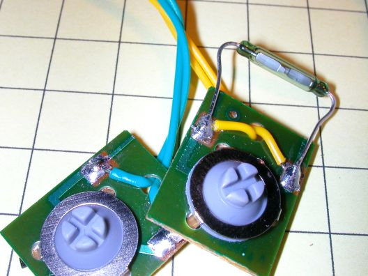
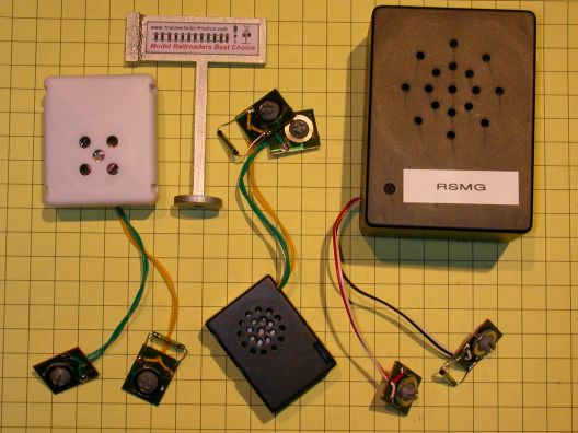
The photo below shows the RSM (black case) and RSMO (white case) modules. The RSM is designed to fit inside of HO scale cars while the larger RSMO is designed for O scale. The record and playback switches can be seen as well.
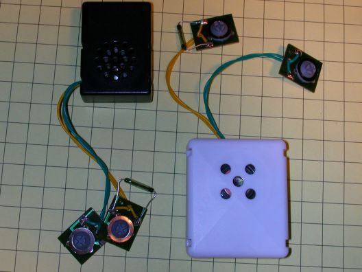
The playback switch can be pressed to activate the sound or a magnet can be used to activate the sound by way of the reed switch that is soldered to the side of the playback switch.
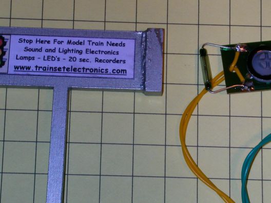
Included with the RSM and RSMO modules is a clever sign, pictured below, that has a powerful magnet glued to its side. The intent of this design is to have the sign mounted near the edge of the track so that a boxcar, containing the sound module and reed switch, passes near enough to the sign to be triggered each time the train passes. This is a nice alternative to putting reed switches on the bottom of cars and burying magnets in ballast. I found the magnet attached to the sign to be strong enough to trigger the reed switch at a distance of at least 1".
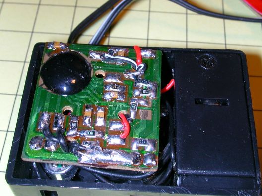
I disassembled the RSM unit to examine its components. Even though I did not attempt to connect the module to external power, a direct audio input from a computer or an external speaker / amplifier as I did the other items in this article I am confident that those modifications could easily be made.
The models pictured above were not specifically designed for G scale or outdoor use. The volume is more than sufficient for indoor layouts but is likely to be lost in the out of doors. As I was completing this article I received the latest product from the folks at http://trainsetelectronics.com, RSMG, designed for use in G scale train systems. It is considerable larger then the HO and O scale units as you can see in this picture.
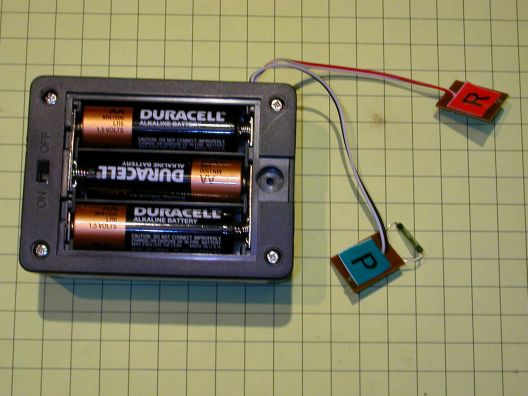
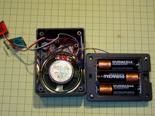
It runs from 3 AA batteries which is sure to give you much time between battery replacements. The unit works in the same manner as the others except for the addition of an on/off switch on the back of the case. The volume is quite a bit louder than the others and I am sure it would work much better on an outdoor layout than the others.
I tested the sound reproduction of the RSMO and the RSMG using the same procedure as with the other boards. I tried to give some idea of the difference in volume between the RSMO and RSMG by keeping the distance between the microphone and speaker the same as these recordings were being made.
The units from Train Set Electronics range in $15.40 for the RSM module to $20.20 for the RSMO. Check their web page for the price on the new RSMG.
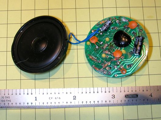
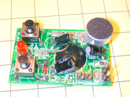
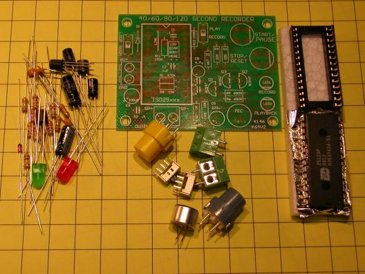
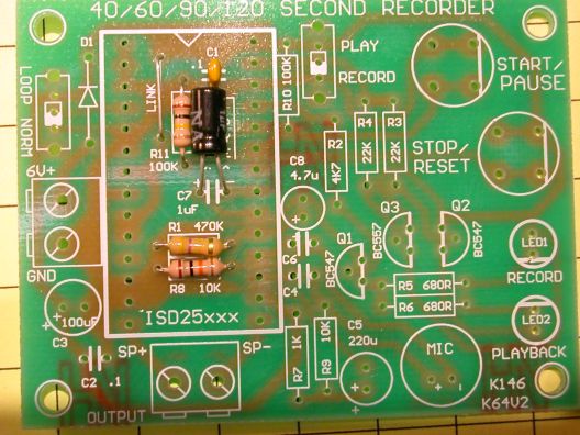
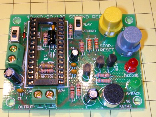
120 Second, Multi-Message Board
The company that manufactures the amplifier boards that were used in this project, www.Qkits.com, also has a number of sound and voice recording kits. To me, the most intriguing board utilizes a sound recording chip that can record up to 120 seconds of sound. That in itself is impressive but the most interesting part of the board is that many short messages can be recorded on the chip and played back individually. This would allow you, for example, to record 10 messages each with a duration of 12 seconds and play them in sequence, one at a time, each time the play switch is activated.
Qkits offers two different versions of this board, one that records up to 120 seconds (qk146b - $28.95) and one that records for up to 40 seconds (qk146 - $18.95). You can also order just the sound recording chip from Jameco.com. Since the IC used in the kit is in a socket and supports 40, 60, 90 and 120 second chips you could easily change chips as your needs change.
My plans for this board involve installing it and a magnetically activated reed switch in one of my stations. The reed switch will be positioned near the track so that it will be activated whenever a train (carrying a magnet) passes by. When this happens the first recorded message will be played. The second time the train passes the second recorded message will be played and so on until all 120 seconds of messages have been played and it repeats.
Because my railway's
primary reason for existence is to transport prehistoric coffee beans from the
Cretaceous Coffee Mine to the Wizard's Cup Coffee Refinery and to distribute
refined coffee to various stops along the way some of the announcements will
include:
"All aboard for the best coffee for the last 100,000,000 years"
"Next stop caffeine station #1"
"Giant pre-historic coffee beans on sale in the gift shop"
"Coffee lovers only now boarding on track one"
"D & L Railroad train 243 departing for Wizard's Cup Coffee Refinery tour"
This scenario of operation is possible without any modifications to the kit. If a simple microprocessor (see: LSOL article "Robot Trains in the Garden") is added the microprocessor can pick one of the recorded messages at random rather than having them always play in sequence. This does complicate things a bit and random repetition could easily be simulated by recording the above 5 messages over and over in random order until the entire 120 second capacity of the board is filled. Since each of these messages takes only a few seconds of recording time I think that solution might be the simplest!
Construction:
The kit is easy to assemble and everything you need to complete the kit is included except for a speaker and batteries.
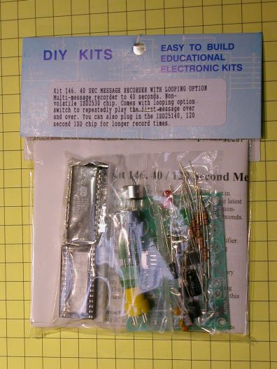
The instructions are not meant for a beginner so I have taken a number of photos that should help in setting up a sequence for construction.
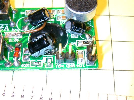
First install and solder the components that go under the integrated circuit socket. Keep leads short and install the components as shown.
Next install the rest of the resistors...
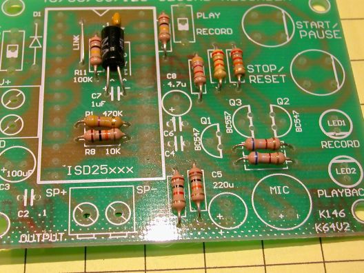
and the capacitors. Note that the electrolytic capacitors have a + (longer) lead and a - (marked on the case) lead. The other capacitors can go in either way.
Install the three transistors and the diode. The direction of the diode is marked on the board. The transistor locations and identifiers are also clearly marked on the board. There are two BC547s (Q1 & Q2) and one BC557 (Q3).
![]()
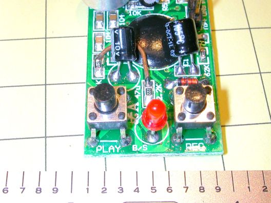
Install the remaining components. The two "top hat" switches have a flat side that must be installed as marked on the board. The microphone must be oriented with + and - as marked.
After you are done soldering carefully examine the back of the board and make sure there are no solder bridges or cold solder joints.
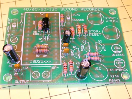
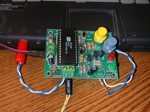
Hook up a speaker and power supply and test as per the instructions. You should be rewarded by a clear reproduction of your test message. Start to finish it took me a bit under 30 minutes from opening the kit to recording my first test.
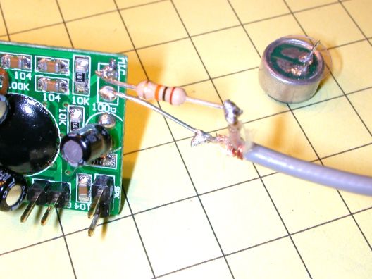
Here is a picture of the test setup using an old laptop as the sound source. In this picture the sound board is directly connected to the audio out jack on the laptop through a 10K resistor. You may notice that I did not use the green connection blocks for power and speaker but soldered pins to the bottom of the board so that I could use the quick plug in connectors from an old computer, thus the label on one plug in the picture "TURBO LED"!
Amplifiers
The first article gives information on small amplifiers that can be used with these sound modules but you must take great care in connecting them. The amplifier boards typically have three sets of connections. One for the positive and negative terminals of the battery or power supply, one for the speaker and one for the input from an audio source. My first instinct when hooking up an amplifier was to connect the input for the amplifier to the speaker output from the sound board. This proved to be wrong and the source of much frustration until I figured out what needed to be done. The best solution was to use the same battery or power supply for both the sound board and amplifier. This simplifies things, as you only need one power source, but it also gives the two boards a common ground since both share the negative, or ground, power lead. Once this is done connect only one of the speaker output pins from the sound board to the single audio input pin on the amplifier. Leave the second speaker output pin unconnected. You may have to experiment a bit to get the right one connected but it works well once you get it right!
Good luck, enjoy your railroad's new voice and please let me know how you use sound on your railway!