5 Volt Power for Railway
Electronics
revised 12-13-07
As we add more and more electronic devices to our garden railways we frequently have a need to provide regulated 5 volt power to those devices. Items like microprocessors, sound boards, LED lighting systems and some smoke generators work best if they are supplied with a stable, predictable power source. Some will even fail instantly if voltages rise above their maximum threshold.
Since that need for voltage regulation is something that most of us run into at some time I have put together some notes that you might find useful when that need arises.
Large Scale Voltages
Most of our engines and accessories are designed to run from track power. This is typically direct current (DC) that ranges from 0 volts to a maximum of about 24 volts. This variable voltage is great for controlling the speed of an electric motor but it plays havoc with lights, smoke generators and sound boards that may also reside inside of an engine. For example, lights are frequently dim when the engine is running at low speed and smoke generators usually don't operate until an engine is running at a fair clip. We are used to such things and put up with them but they are not very prototypical. Real engines do produce more smoke at speed but also produce it when idling and the speed of a real engine has nothing to do with the brightness of cab and head lights!
Power Conditioning
In order to deliver 5 volts to these devices from track power three things need to be done:
All that needs to be added to that circuit is a voltage rectifier and you have:
Components
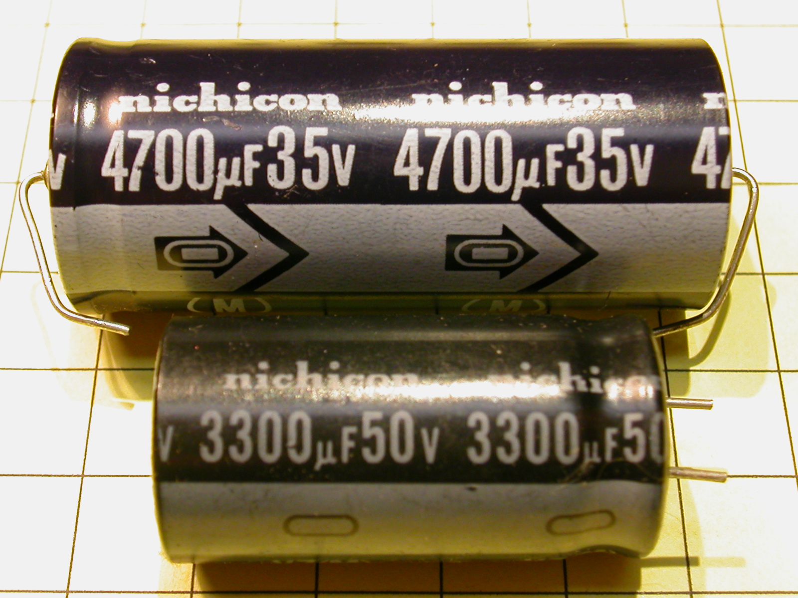
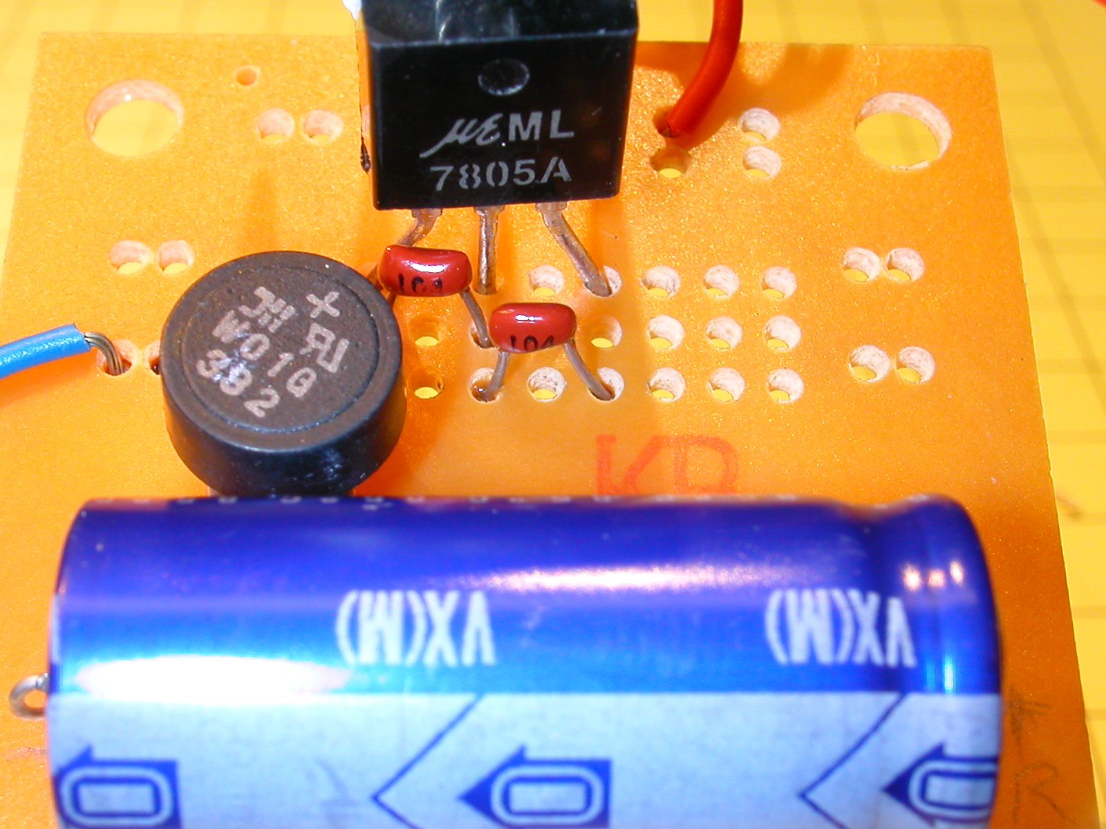
The value of the electrolytic capacitor (C1) is not critical, any value from 1000 µF up should work well. Just make sure the voltage rating is at least 35 volts. I made the mistake of using a capacitor rated at 16 volts in a similar application and heard a loud "bang" when the track power went to full voltage! . Make sure you observe the proper polarity with electrolytic capacitors, too. There is generally a clear indication of which lead is negative, as you can see in the photos. Reversing the polarity can also lead to loud consequences! C2 and C3 are .1 µF capacitors. Their primary purpose is to keep the 7805 from going into oscillation and shutting down
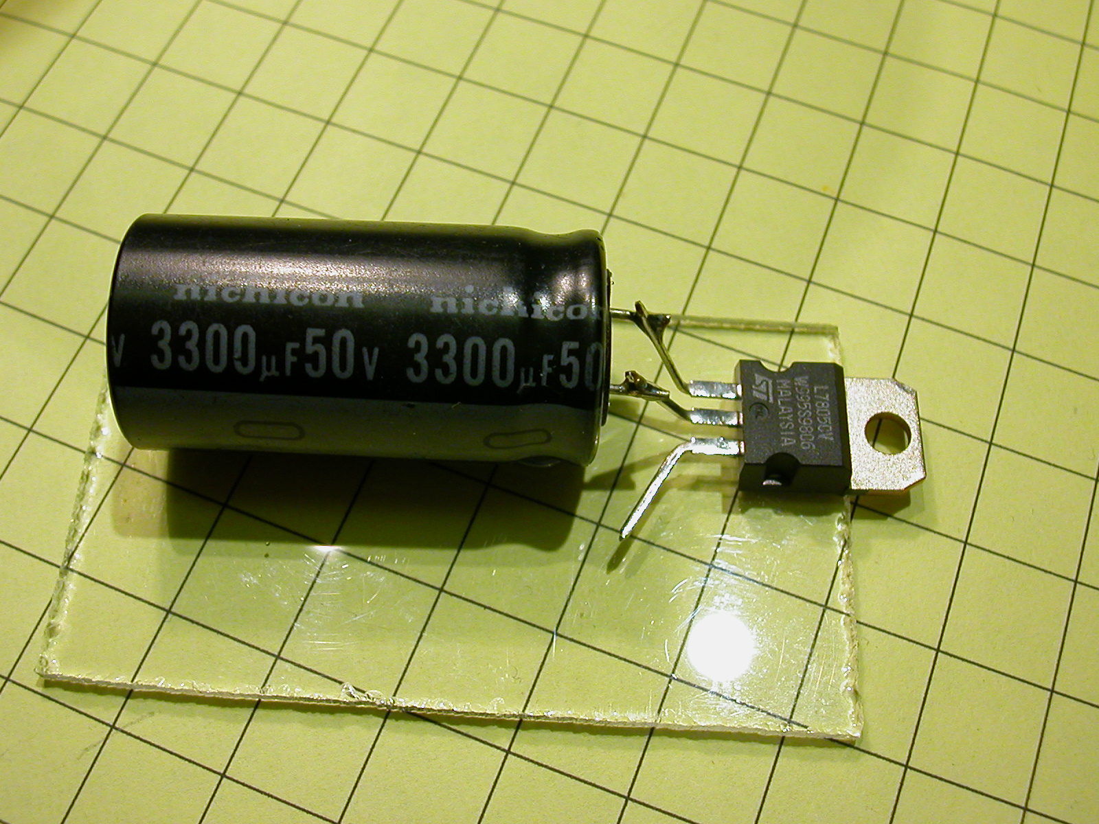
This photo shows an axial capacitor with its leads coming from both ends (top of photo) and a radial capacitor with both leads coming from one end. They both work equally well. The choice between them is mainly for convenience in mounting. Note the marking of the negative pin (the one on the right of the top cap and the one on the bottom of the bottom cap) and the voltage ratings (35 volts and 50 volts)
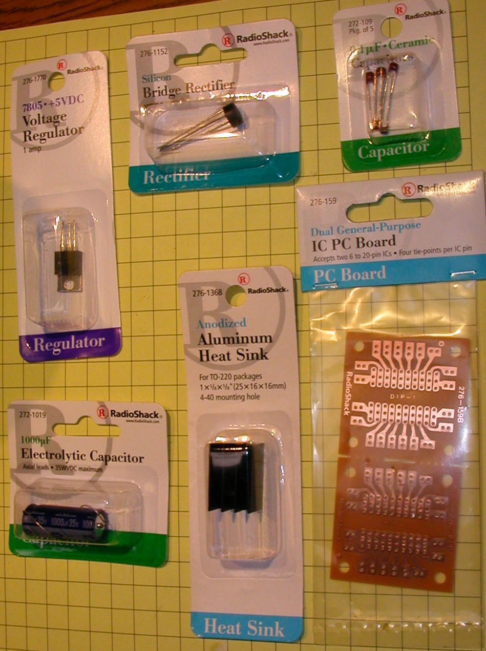
The 7805 voltage regulator comes in a number of power ratings. The most common is rated at 1 amp. You can use the smaller rated regulators (.5 amp and .1 amp) if you are sure your project needs no more power than the rating. If you will be drawing even 1/2 of the rated maximum current you must use a heatsink. A heatsink is just a piece of metal, usually aluminum, that is securely fastened to the large tab on the TO-220 case of the regulator. When the component heats up the heatsink helps to dissipate the heat. Good quality 7805 regulators have a thermal shutdown circuit that will keep them from burning up if too much current is being drawn and the temperature exceeds 125 degrees C. The heatsink will allow you to run higher power devices without getting to the shutdown temperature. In the picture below you can see several different voltage regulators. The first two are both 7805's, the one on the left is rated at 100 ma (1/10 amp) and is appropriate for applications where very little current is needed. They are commonly available in what is called a TO-92 case, the classic transistor case that looks like a small black cylinder with one edge ground flat. The second regulator is a 1 amp 7805 in a TO-220 case. The TO-220 has a large metal tab at the top that is electrically connected to ground and is used to attach an external heatsink. The other regulators in TO-220 cases are a 7806 and a 7812. They are 6 and 12 volt regulators, respectively.
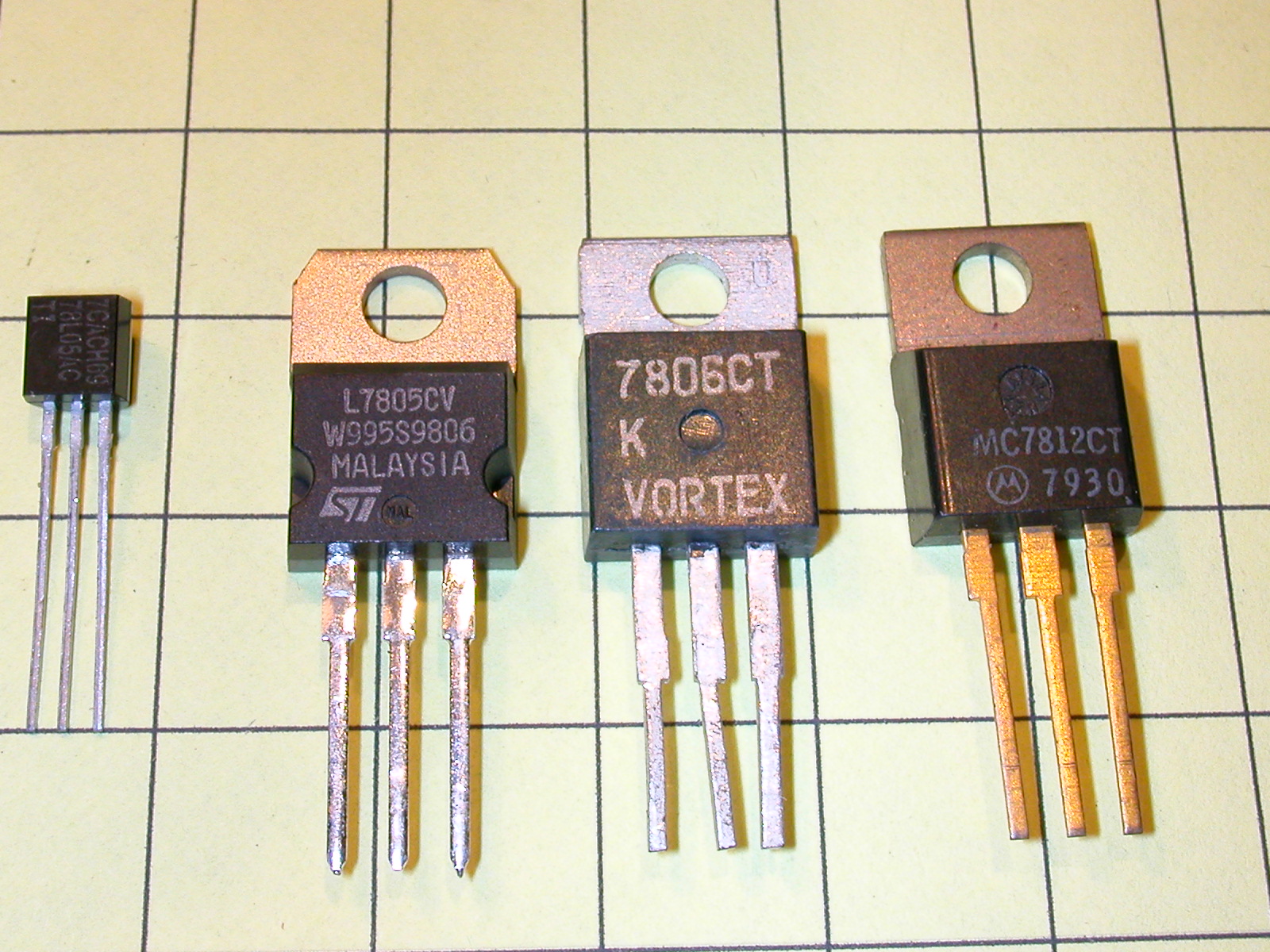
In each case the left lead (as you see the regulators in the photo) is the input connection, the center lead is ground and the right lead is the output.
Construction
If this circuit is going to be a part of a larger project it can be constructed on a circuit board. If it to be a stand alone circuit and space is an issue you can use what is commonly referred to as "dead bug" construction techniques. I made prototypes utilizing both methods and used the following materials:
Dead Bug Method
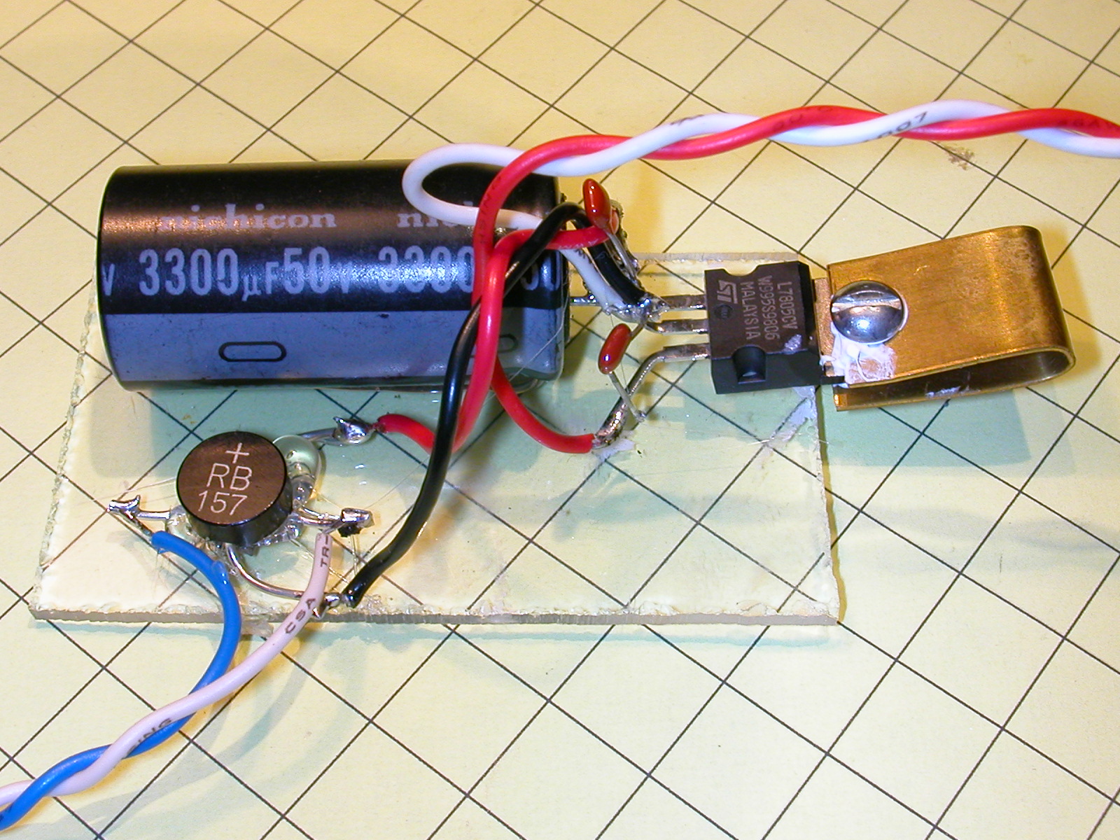
Start by gluing the large capacitor to the Plexiglas with super glue or hot melt glue. In my prototype I used a capacitor from my junk box that is 3300 µF @ 50 volts. Next solder the negative lead of the capacitor to the center lead of the regulator and the positive to the left lead, as in the photo. Don't glue the regulator to the Plexiglas as you need to have it free when it comes time to add the heatsink.
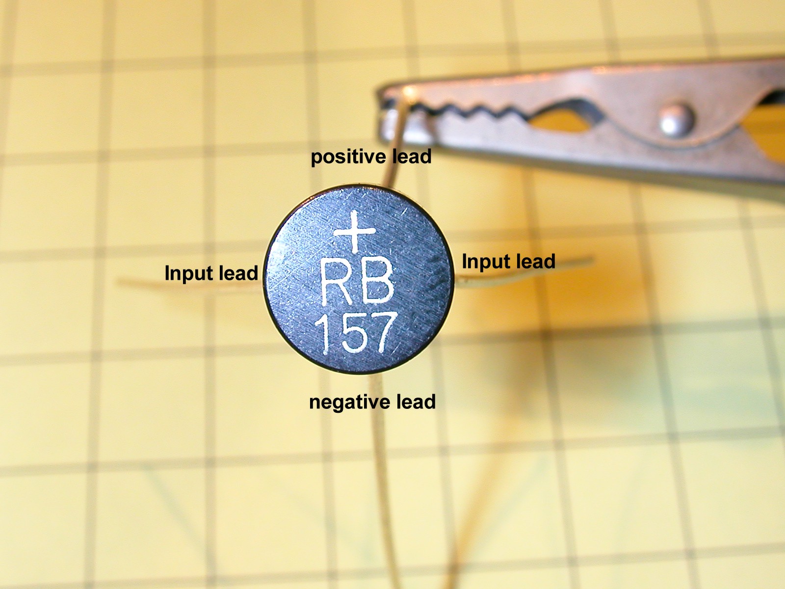
Next identify the leads on the bridge rectifier. There are four leads, two that are connected to the input voltage from the track and a positive and a negative output lead. The positive lead is the only one identified on most rectifiers. It is labeled with a + sign. The lead opposite the + is negative and the two leads in between the + and - are for the input.
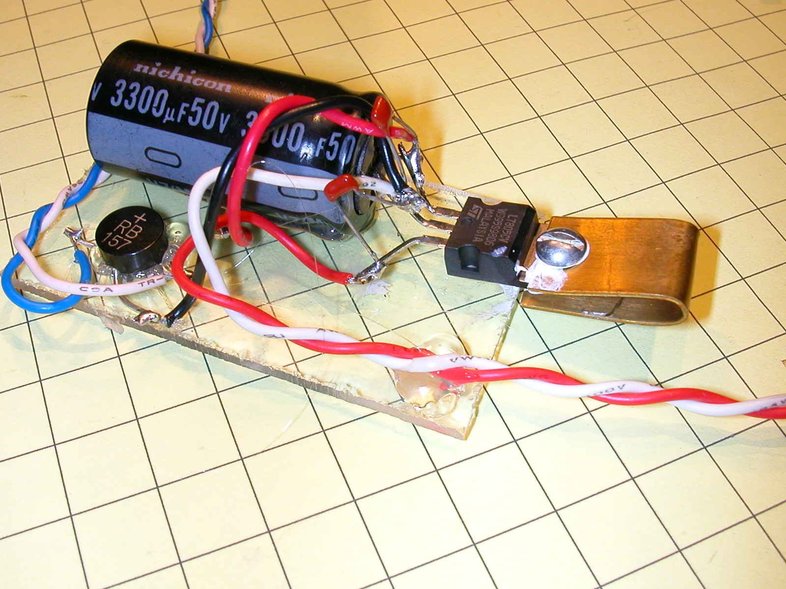
Glue the bridge rectifier to the Plexiglas and complete the wiring as in the schematic and photo. Note that the blue and white wires (bottom left in photo) are the input leads that would go to track power and that the red and white leads (top right) are the 5 volt output leads. You can also see the two small .1µF capacitors. One is soldered between the input lead and ground and the other between the output lead and ground.
A small, and not particularly effective, brass heatsink has also been screwed to the tab on the 7805. The white substance you see on it is heatsink grease, a substance that helps to conduct heat between the 7805 and heatsink. If you have an old computer sitting around waiting to be discarded you can salvage the heatsink that normally sits on top of the CPU. Save the CPU fan, too. I used both of these items during testing.
Circuit Board Method
For the dead bug prototype I used parts from a variety of sources, mostly from my junk box. For the second prototype, I used only parts from the local Radio Shack. This version follows the same schematic.
I have placed the components on the board in a manner that makes hookup easy. Please feel free to place them as you see fit as none of the placement is critical. Just be sure to follow the schematic. If you want to follow my prototype the following photos should help.
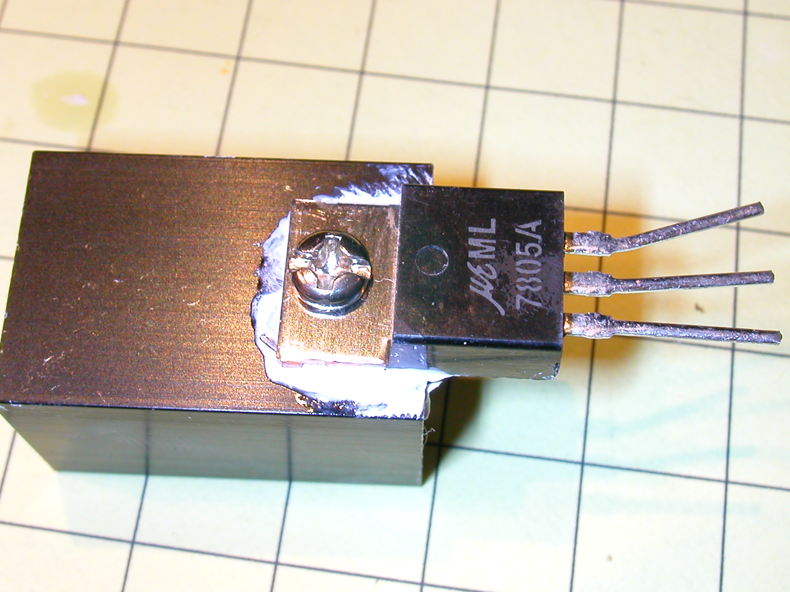
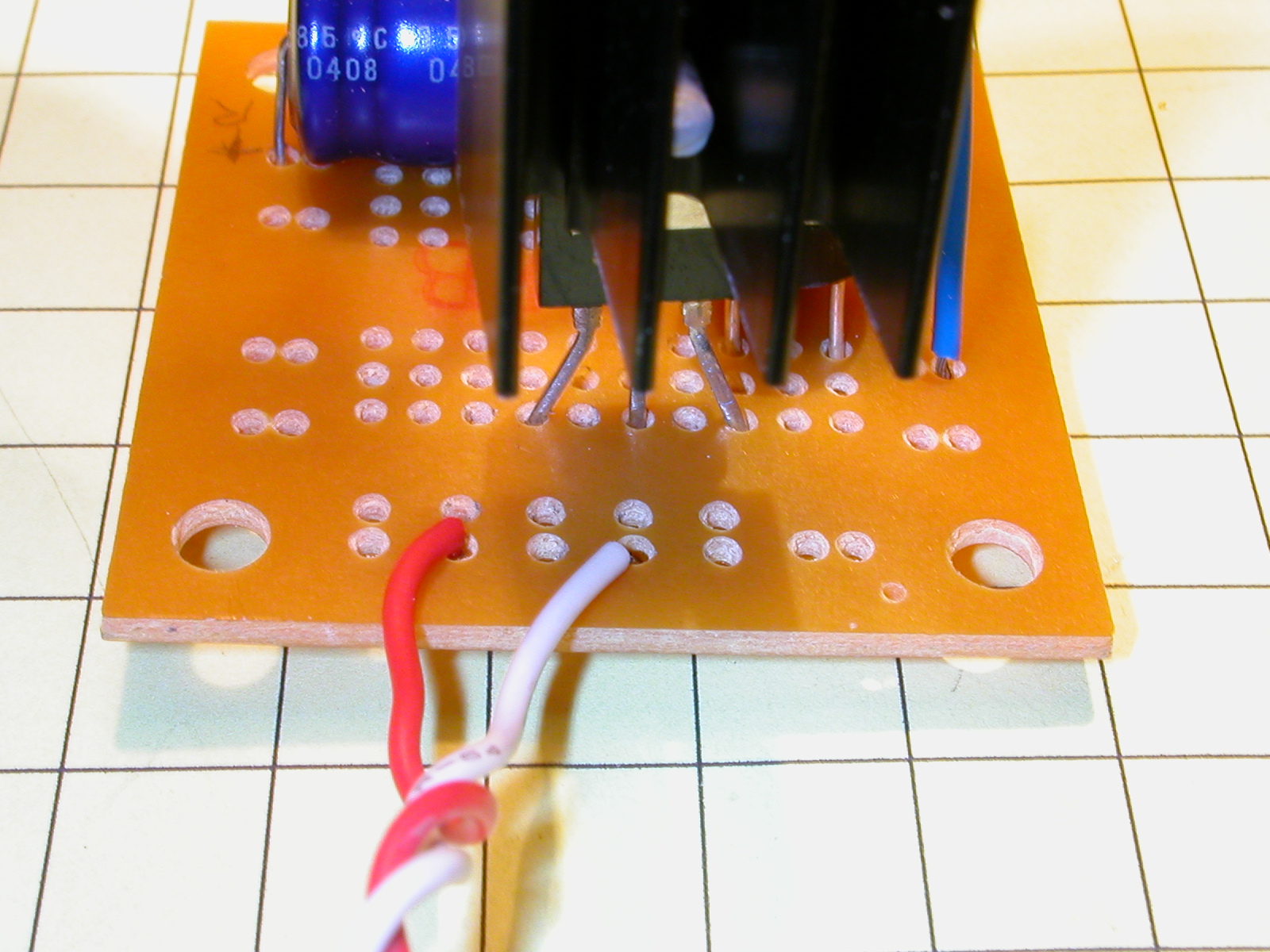
First attach the heatsink to the 7805. Use heatsink grease if you have it. It is not absolutely necessary but can help. Make sure the screw is tightened securely.
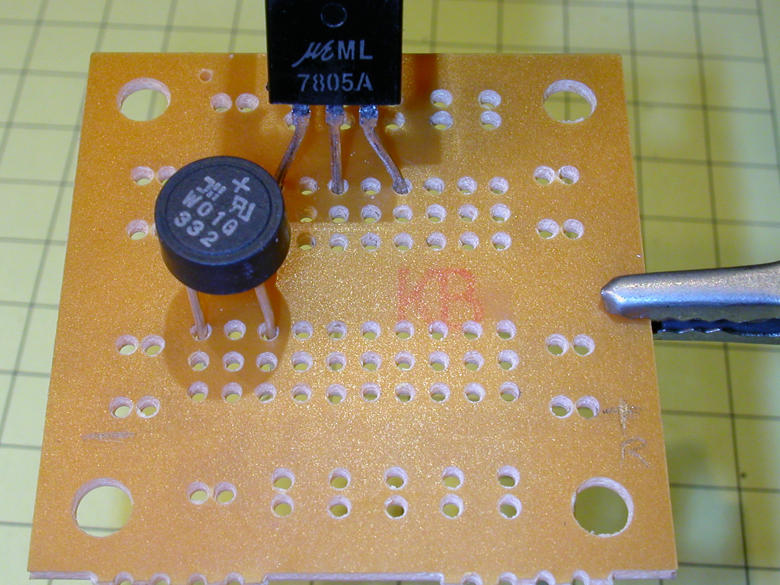
Place the regulator and bridge rectifier. Note the position of the + lead on the rectifier. It goes into the same set of holes that hold the input lead from the 7805.
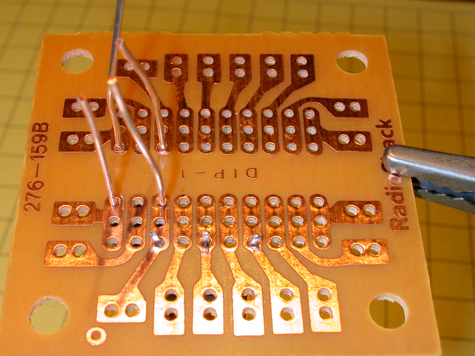
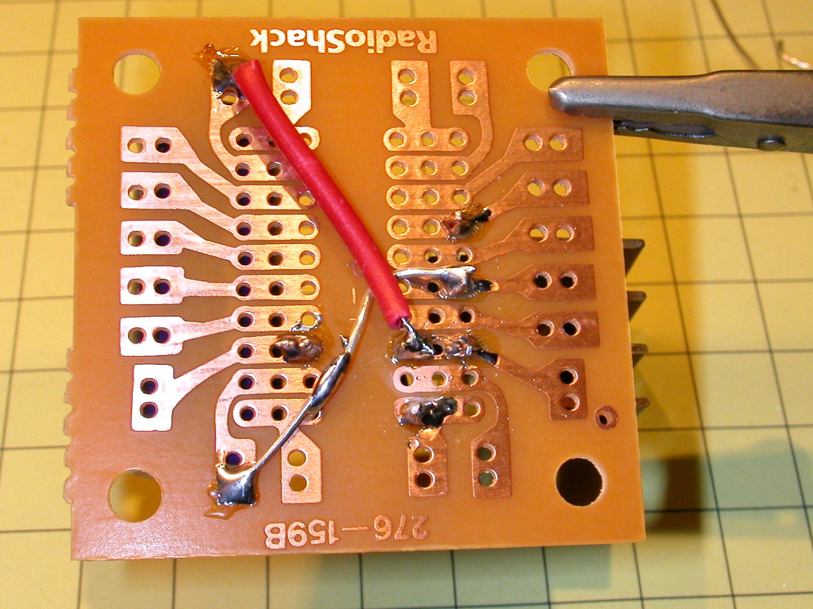
Here is a bottom view before soldering.
Add the capacitor with the negative lead to the left as below.
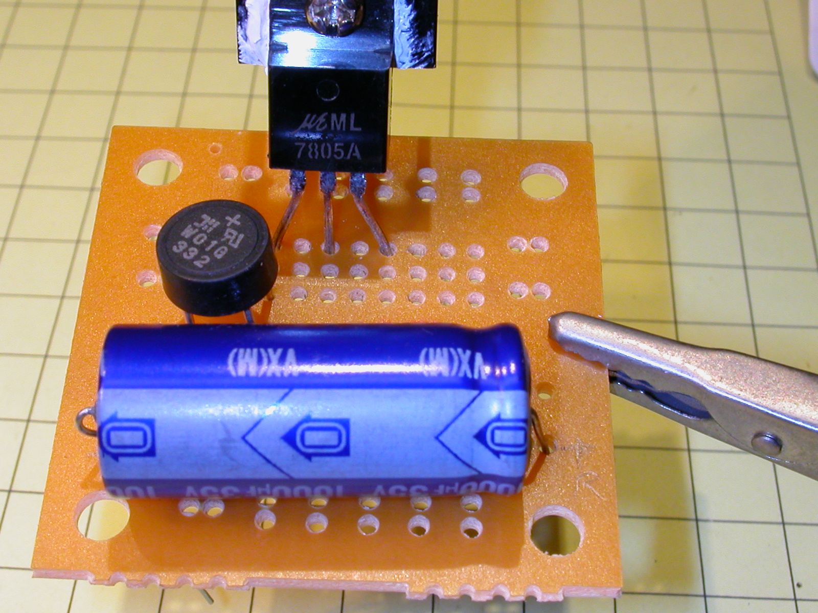
The red material is just a piece of insulation from a scrap wire (commonly referred to as spaghetti) that is slid over the positive lead from the capacitor to keep it from shorting out on other areas of the board. Make sure you clip off the extra wire that extends from the back of the circuit board each time you solder a component.
The blue and white wires are the input from the track.
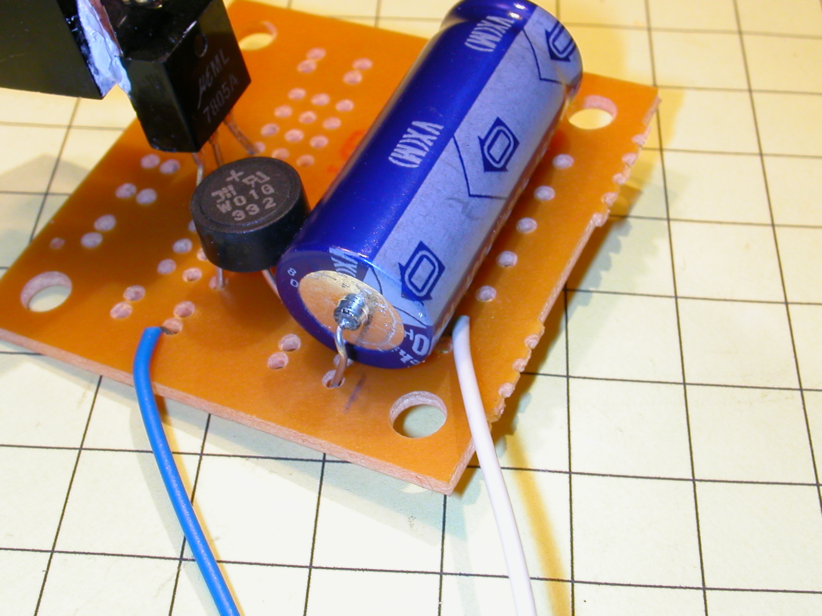
The red and white wires are the 5 volt output (red) and ground (white).
The two small capacitors are added. One goes between ground and the input pin on the 7805 and the other between ground and its output pin. Keep the leads as short as possible.
A power LED was added to facilitate testing. It has a 470 ohm resistor going from the plus 5 volt output to the longer (positive) lead of the LED and the negative lead of the LED (the one with the notch ground in the case) going to ground. When sufficient power is applied from the track the LED lights.
Testing
It is always wise to test a circuit like this with a meter and something other than your sensitive electronic components. I generally put a small incandescent light bulb on the output for testing. That way an error in construction might cause you to lose a $.50 light bulb, not an expensive circuit board. Before hooking anything up to the output connect the circuit to the track power and check the output voltage with a meter. If you installed the power on LED it should light and the meter should show 5 volts +- a few 1/10 volts. If that test is successful disconnect the power and insert a small 6 volt light bulb or other small load. Apply power and see what the voltage is with a load on the circuit. It should still be very close to 5 volts. Quickly touch your finger to the heatsink and see if it is getting warm or hot. Warm is OK and to be expected. Too hot to touch means that the heatsink is too small or the load is too great for the regulator.
Performance Tests
In order to determine the operating characteristics of our 5 volt regulator I performed a number of tests. Light bulbs from an old string of outdoor Christmas lights supplied a consistent set of loads, each of which drew about 1/3 amp at 5 volts (each bulb had a resistance of about 2 ohms). The circuit was hooked up to several volt meters, one measuring the voltage from the track, one measuring the voltage between the bridge rectifier and the voltage regulator (called the reservoir voltage) and one measuring the output voltage coming from the regulator. In addition another meter was placed in series with the output of the regulator and the load to determine the current flowing between them. The last measurement was the temperature of the voltage regulator, measured on the heatsink.
The first test was with the dead bug prototype with a small brass heatsink. The second set of tests was with the same device but with a much larger heatsink, one taken from an old computer. The third set of tests was done with the circuit board prototype and a medium sized Radio Shack heatsink. A small fan, from an old computer CPU cooler, was used for some tests where the 7805 shut down due to excessive heat. Either one, two, three or four bulbs, wired in parallel, were connected to the 5 volt output to supply a load.
This picture shows the test setup:
The results of the tests are in the table below.
| Board | Bulbs in Parallel | Track Voltage | Output Voltage | Current (amps) | heatsink Temperature (F) | Comments - Note: ambient temperature was about 66 degrees F |
| Dead Bug -small sink | 1 | 8.0 v | 4.71 | .33 | 98 | no fan - stable |
| Dead Bug -small sink | 1 | 12.0 v | 4.95 | .34 | 142 | no fan - stable |
| Dead Bug -small sink | 1 | 19.5 v | 4.92 | .34 | 232 | no fan - stable |
| Dead Bug -small sink | 2 | 8.0 v | 4.9 | .64 | 119 | no fan - stable |
| Dead Bug -small sink | 2 | 12.0 v | 4.88 | .68 | 215 | no fan - stable |
| Dead Bug -small sink | 2 | 19.5 v | - | - | 240+ | no fan - shutdown |
| Dead Bug -small sink | 3 | 8.0 v | 4.3 | .95 | 135 | no fan - stable |
| Dead Bug -small sink | 3 | 12.0 v | 4.89 | 1.02 | 240+ | no fan - shutdown @ 240 degrees |
| Dead Bug -small sink | 3 | 19.5 v | - | - | not tested | |
| Dead Bug -small sink | 4 | 8.0 v | 4.19 | 1.26 | 182 | no fan - stable |
| Dead Bug -small sink | 4 | 12.0 v | 4.89 | 1.32 | rapid rise | no fan - shutdown within 10 seconds |
| Dead Bug -small sink | 4 | 19.5 v | - | - | not tested | |
| Dead Bug -large sink | 3 | 8.0 v | 4.3 | .95 | 91 | no fan - stable |
| Dead Bug -large sink | 3 | 12.0 v | 4.89 | 1.02 | 150 | no fan - stable |
| Dead Bug -large sink | 3 | 19.5 v | 4.92 | 1.02 | 240+ / 95 | shutdown without fan (first #) - came back as soon as fan started up |
| Dead Bug -large sink | 4 | 8.0 v | 4.19 | 1.26 | 112 | stable without fan |
| Dead Bug -large sink | 4 | 12.0 v | 4.91 | 1.36 | 179 | stable without fan |
| Dead Bug -large sink | 4 | 19.5 v | 4.87 | 1.35 | 103 | stable with fan |
| Circuit Board | 1 | 8.0 v | 4.67 | .33 | 85 | no fan - stable |
| Circuit Board | 1 | 12.0 v | 4.92 | .34 | 116 | no fan - stable |
| Circuit Board | 1 | 19.5 v | 4.95 | .34 | 182 | no fan - stable |
| Circuit Board | 2 | 8.0 v | 4.55 | .65 | 106 | no fan - stable |
| Circuit Board | 2 | 12.0 v | 4.96 | .68 | 168 | no fan - stable |
| Circuit Board | 2 | 19.5 v | 4.96 | .69 | 240+ / 107 | shutdown without fan (first #) stable with fan |
| Circuit Board | 3 | 8.0 v | 4.46 | .97 | 134 / 82 | stable without fan (first #) and with fan |
| Circuit Board | 3 | 12.0 v | 4.98 | 1.03 | 201 / 106 | stable without fan (first #) and with fan |
| Circuit Board | 3 | 19.5 v | 4.97 | 1.03 | 127 | stable with fan - not tested w/o fan |
| Circuit Board | 4 | 8.0 v | 4.01 | 1.22 | 151 / 91 | stable without fan (first #) and with fan |
| Circuit Board | 4 | 12.0 v | 4.94 | 1.37 | 240+ / 114 | shutdown without fan - stable with fan |
| Circuit Board | 4 | 19.5 v | - | - | - | shutdown immediately |
Here are some observations:
If you are drawing less that 1/3 amp not much of a heatsink is needed, if any, regardless of the input voltage. It is unlikely that you would ever go above this with simple electronic circuits or a string of high intensity LEDs.
To give you an idea of how little current LEDs use I wired 6 high output LEDs, each with an individual 470 ohm series resistor, in parallel and connected it to this device and the ammeter showed the current to be 0.03 amps, roughly 1/10 of the current drawn by the one small incandescent bulb used in these tests.
As the current drawn and/or the voltage supplied from the track goes up a heatsink becomes necessary
Large heatsinks are much better than small ones
Fans, even small ones, make a dramatic difference in the efficiency of the heatsink
Good quality voltage regulators shut down when their internal temperature becomes excessive and automatically start up when the temperature drops.
The regulators tested were able to supply significantly more than their rated amperage so long as they were kept cool.
It would be wise to test the current needed by a component, such as a smoke generator, before installing it in an engine.
Getting More Power
Although it is possible to connect voltage regulators in parallel to increase the current that is available it is not an accepted method. If you need more than 1 amp of continuous current a 2nd device, a 3055 power transistor can be used to supply up to 5 amps. These devices can safely be wired in parallel to provide even higher output. The circuit to connect one 3055 to our regulator is below. Adding the 3055 is a simple task, just make sure that you use a large heatsink and fan if you are drawing much more than 1 amp. In my tests I lighted 7 bulbs, drawing 2.15 amps. The heatsink on the 7805 stayed cool and the one on the 3055 got very hot and I needed to run a fan with it.
Adding the 3055 is involves connecting the positive output from the 7805 to the base of the 3055. The collector goes to the positive output of the bridge rectifier. The output of the 3055 is the emitter where + 5 volts will be available. Although it is not likely that the 7805 will get very hot in this application as it is being used as a driver, not the main power device, make sure that you don't try to put the 7805 and 3055 on the same heatsink unless you take steps to isolate the metal tab on each device from the heatsink or you will be creating a short circuit.
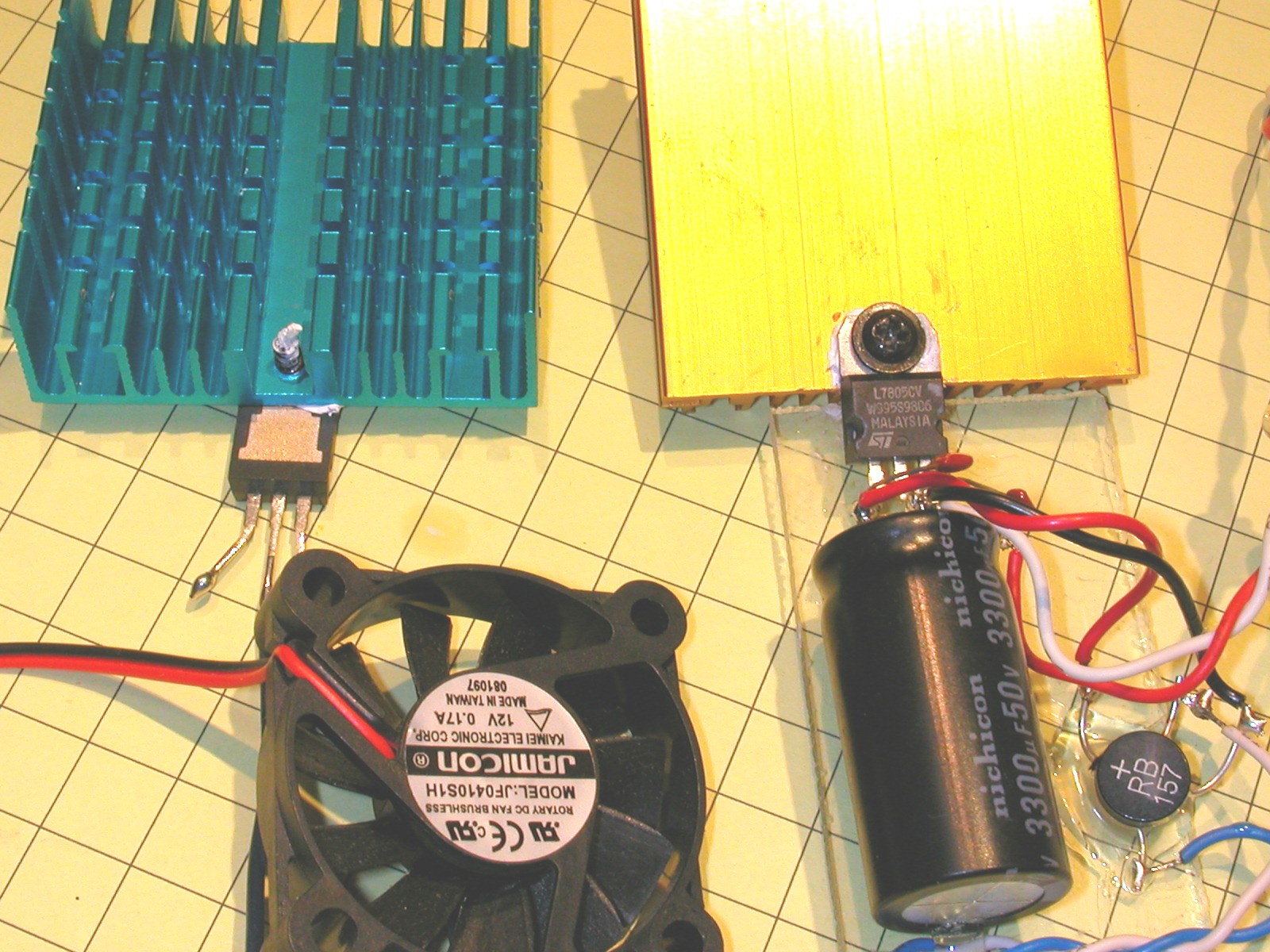
Below is a picture of the 3055 (on the blue heatsink on the left) and the 7805 connected to old computer CPU heatsinks. Both components were connected with sheet metal screws that were threaded into holes drilled near the edge of the heatsinks. The fan was used to cool the heatsinks. It was also from an old computer.
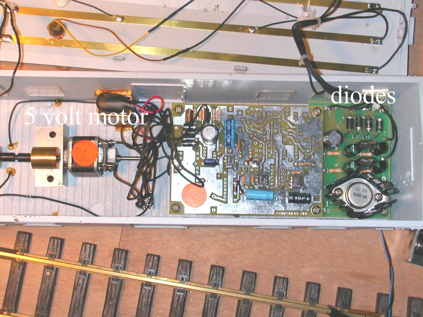
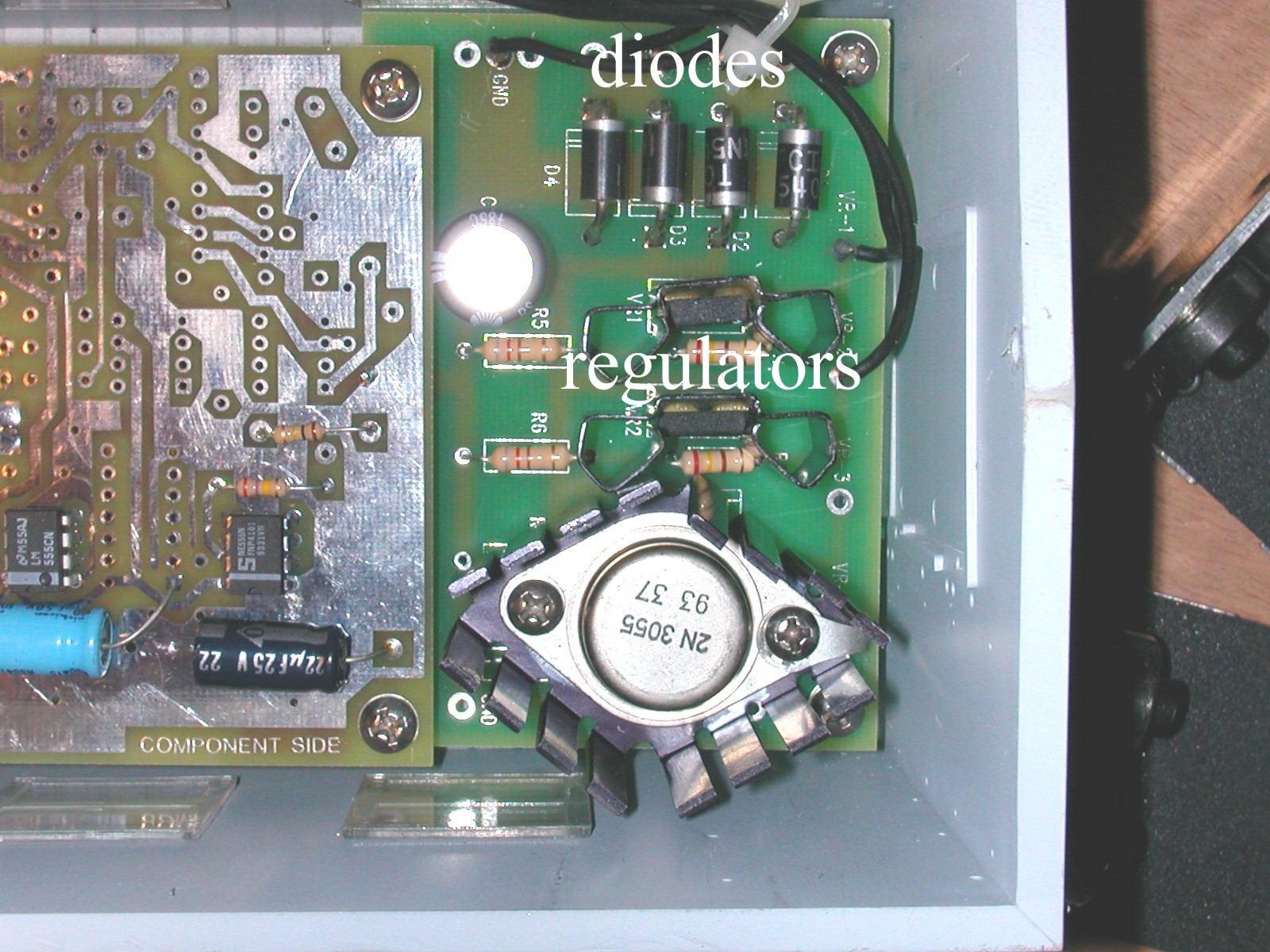
These two photos are of the circuitry inside of the USA Trains Rotary snow plow. The section to the far right is a 5 volt, high current power supply that includes a 3055 transistor. It is used to power the 5 volt motor that drives the rotating turbine at the front of the car. By running it on 5 volts it can get up to speed from low voltage track power. The regulator circuit is necessary to keep it from burning up when the track power gets too high. You may also notice the 4 diodes stacked together in the top right corner. They make up a bridge rectifier that is identical in operation to the one we are using even though it is made up of 4 individual diodes. The 3055 in this picture is the same as the one we are using but it is in a TO-3 case rather than the TO-220 utilized in this article.
Other Considerations
If you are running your engines on battery power and need much more than a few 1/10s of an amp of power at 5 volts you are probably better off using a separate set of 4 rechargeable cells rather than running this type of circuit off from battery power. All of that heat that we are experiencing would mean that your run time on batteries would be shortened considerably. Another alternative would be a DC to DC converter which is a much more efficient device. Hosfelt (www.hosfelt.com) has such a device (part 56-630) that takes an input voltage up to +24 volts and delivers +5 and +12 volts at up to 1.5 amps.
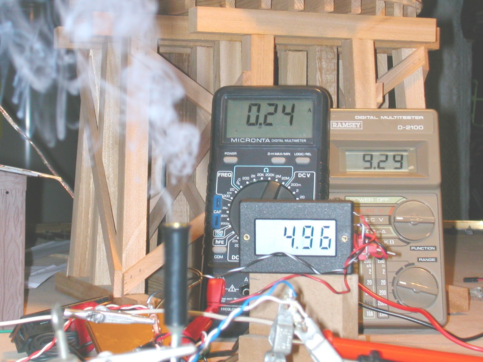
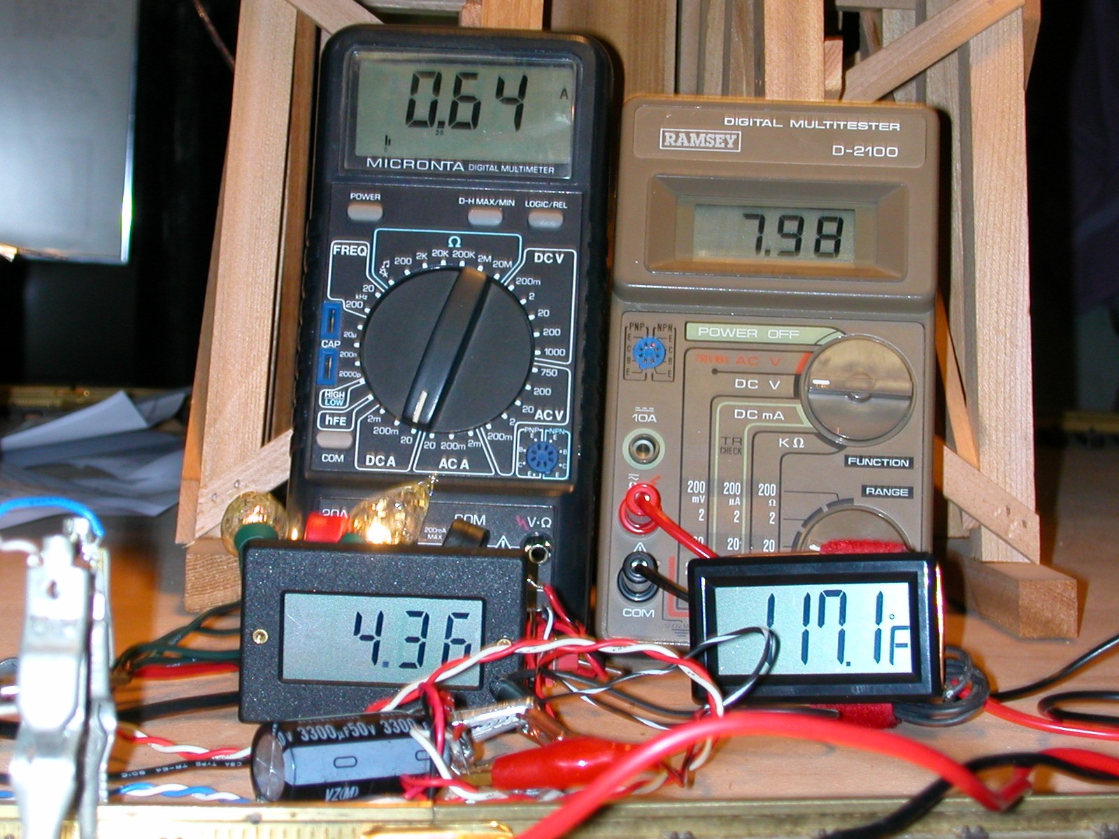
Smoke generators, such as the LGB # 65853 and the similar Seuthe #5 are designed for 5 volt operation. The Seuthe unit that I tested draws .25 amps at 5 volts and should work well with the 7805 circuit as long as a heat sink is included. The photo below shows the test setup with the smoke generator in the foreground and meters showing .24 amps being drawn at 4.96 volts when there is 9.29 volts on the track.