
Blinking Auto-Reverse Unit (BARC)
When I was testing the capacitors and thermistors that were the focus of two recent articles I had a need for a simple controller that would automatically reverse a small engine that was running on a point-to-point track.
Even though I had made up a very nice auto-reverse unit, complete with an LCD display and lots of features, for my holiday incline project, I wanted something simpler that would only do the basic reversing of an engine that I needed for testing.
This led me to develop an extremely simple unit that contained only a few parts.
Pausing between reversals and control of the relay was done with a Picaxe 08M microprocessor. It was programmed to:
Diodes were inserted in cut sections of track at each end of the point-to-point layout that would bring the train to a complete stop when it passed beyond them. See page 8 of my recent article on Thermistors for details on how this is done. http://www.largescaleonline.com/members/emag/article_515.html?page=8
This simple program did the trick and made my work with the capacitors and thermistors (see: http://www.largescaleonline.com/members/emag/article_500.html and http://www.largescaleonline.com/members/emag/article_515.html ) much more efficient.
The simplified schematic is below and shows the minimal circuitry that was
needed to make it all happen.
Additional Features
After completing my work with the capacitors and thermistors I revisited this simple auto reverse circuit. Many LSOL members had sent me emails asking that I explain in more detail what I had done and I wanted to clean it up a bit before writing about it. As I mulled this over I began to think about features that I might want to add.
My "wish list" included:
All this and I wanted to keep the parts count down so that I could make completed units available at a reasonable cost! Not an easy task but a place to start.
The next step was to make some compromises. One always has to balance features and cost and the display was the obvious place to keep the price down. LCD displays, such as those that I use in the train speedometer (see: http://www.largescaleonline.com/members/emag/article_477.html ) are very nice but can double the cost of a circuit. Not only does the display itself add to the cost but the microprocessor and other circuitry to support it is also more expensive.
LEDs to the Rescue!
Rather than use the LCD display I felt that I could use a few LEDs to give much of the information that I wanted to provide. Since users would not need to consult the display too often once the unit was working that seemed to be an acceptable compromise.
I began to experiment with LEDs and settled on using 3 of them to show the time settings, laps completed and other numeric information. I wanted to be able to display numbers at least in the hundreds and I could use one of the LEDs to represent 1's, another to represent 10's and the third to represent 100's. If I wanted to show a time of 148 seconds I would have the 100's LED flash once, the 10's LED flash 4 times and the 1's LED flash 8 times. This is certainly not as easy as seeing "148 seconds" displayed on an LCD display but I tried it out and it worked!
An additional LED would show if the random time option was set.
Changing Settings
Once the four LED display design was settled I began to think about the controls that the unit would need to set such things as delay time, train speed and the random time option.
Most of us are used to turning a potentiometer to adjust things. The volume control on a stereo or radio is an example of using a potentiometer to increase or decrease a setting. Most microprocessors have the ability to read the position of a potentiometer so I decided to add one for time adjustment.
This brought up another related design consideration, the maximum time that could be set by the potentiometer. I decided that 255 seconds would be a good maximum time between reversals. Before you think that I have gone off of the deep end choosing such a strange number, rest assured that it makes complete sense! Computers don't deal with numbers in the same way as we humans do. They think in binary or base 2. To a computer thinking in base 2, 255 is a very common number. It is one less than 2 to the 8th power. Kind of like the computer equivalent of "999" which is one less than 10 to the 3rd power.
In any event, 255 seconds is a bit over 4 minutes and seemed like plenty of time for most applications. Turning the potentiometer all the way clockwise would set 255 seconds and turning it all the way counter clockwise would set it to 0 seconds. In reality I adjusted the program to never allow a 0 second delay as such a short delay would drive the train crazy!
Next I added a single button to invoke such things as turning the random time function on and off.
Additional Hardware
Before doing much more with the controls I realized that I would need to add a bit of hardware to the unit to provide for acceleration and deceleration.
Just putting full power to the train and stopping it with diodes in the track would not be a very good way to run a railroad! An additional power transistor could be configured to use Pulse Width Modulation to moderate the train's speed. I have used PWM in a number of other projects and have written about it in at least 10 articles so I'll not take time now to expand on how it works other than to say that it is a simple way for a microprocessor to adjust the speed of an electric motor from full stop to full speed ahead.
Now that we have added a speed controller I could see that a second potentiometer would be needed to adjust the train's top and bottom speed. I also added a second button to simplify selecting options.
Nearing a Final Design
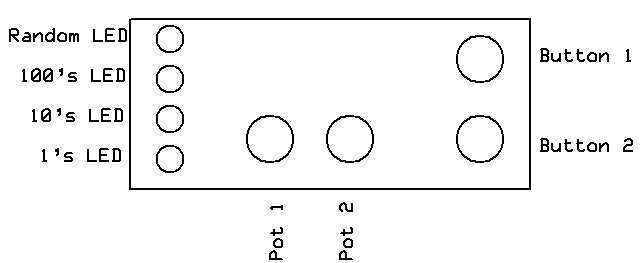
With the controls, display and hardware issues settled the unit looked like this. The four LEDs are to the left, the two adjustment potentiometers are at the bottom and the two setting buttons are on the right.
Software, the Magic that Makes it Work!
A microprocessor based device can have the greatest hardware in the world but it won't do anything without a computer program, or software, to tell it what to do. Designing such software can be the most challenging part of a project like this but it can be great fun, too, as you make the lights and controls come alive to do your bidding!
Routines needed to be written to do various tasks that included:
End User Instructions
One of the other important considerations, which is intimately tied to the hardware and software, is the way that the end-user will interact with the device. This can be the toughest part of the design as one needs to anticipate how users will interpret instructions and, more importantly, how they will misinterpret them!
Connections
There are only two sets of connections on the auto reverse controller. One pair of wires goes to the track, between the two diode protected sections. The other connection is to DC power. As designed this unit will operate most small G scale trains with just a 12-20 volt, 1-2 amp wall wart power supply. The only other consideration is to make sure that proper polarity is observed as connecting the positive and negative wires from the power supply backwards can damage the components.
Making it Work