Limit Switches and the
Rotating Conductors
d. bodnar revised 8-01-18
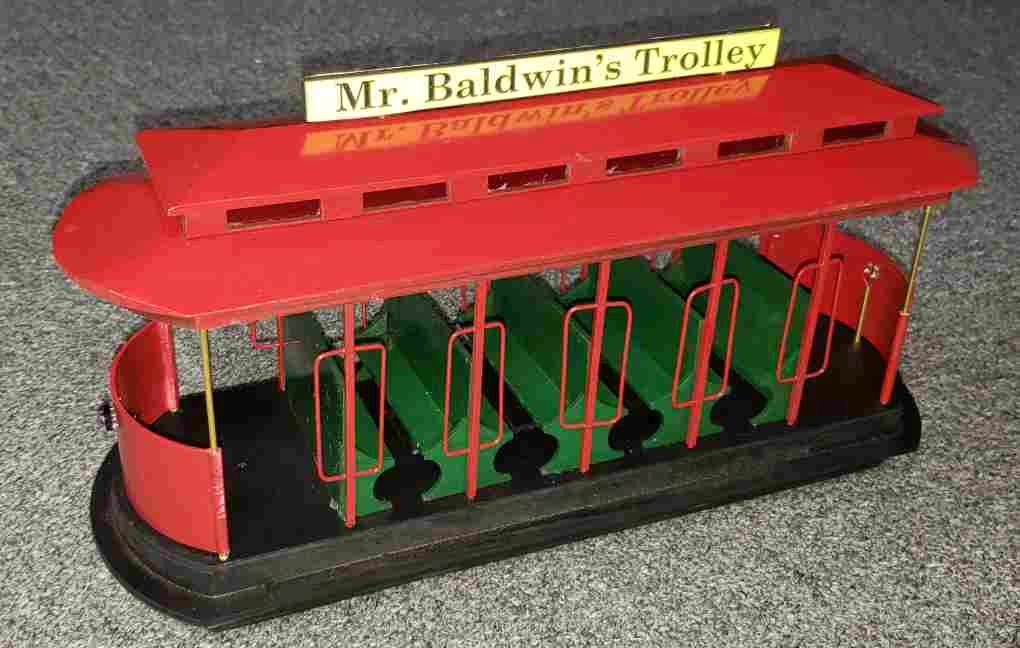
| Introduction While there are a host of ways to rotate an object using motors, servos or other devices a simple gear motor provides an inexpensive and reliable alternative. I recently built a large scale trolley that will be installed at the local children's library to commemorate a friend who has passed away.
The trolley is symmetrical at each end and I wanted to have two conductors on the trolley, one at each end. Since the trolley is set to follow a single run of track in a point-to-point configuration the conductors would be facing in the wrong direction half of the time. I could, of course, have both conductors facing forward but I thought it would be better to have them rotate so that they both faced in the direction of travel. Thus began a quest to find a reliable and simple way to get the two conductors to change direction at each end of the point-to-point. |
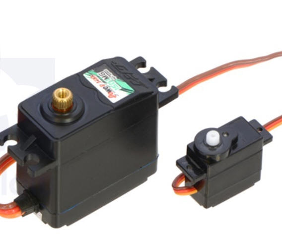
| Options I have used small servos to move things in a number of animations (see:https://www.google.com/search?q=servo+animation&sitesearch=trainelectronics.com for several examples) Because of space limitations I would be unable to use a standard size servo, which I have found to be very reliable. I would be limited to using small, micro servos. These devices work well but typically are built with non-metal gears that tend to fail more often than their larger brothers. In addition servos require some sort of control circuit to tell them how to rotate. This also means that a power voltage regulator & filtering circuit would be needed. The other option that I considered was a small geared motor. I have used these devices and, with their metal gears, they have worked very well.
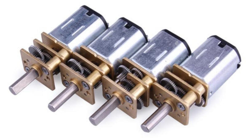
They are inexpensive and are available in a number of gear ratios. I chose a slow rotation rate. They were purchased from Banggood but are available from other vendors including Amazon. The geared motor has more than enough torque to rotate the conductor so all that is needed to make this work is to find a way to get the motor to turn 180 degrees each time the trolley changes direction. |
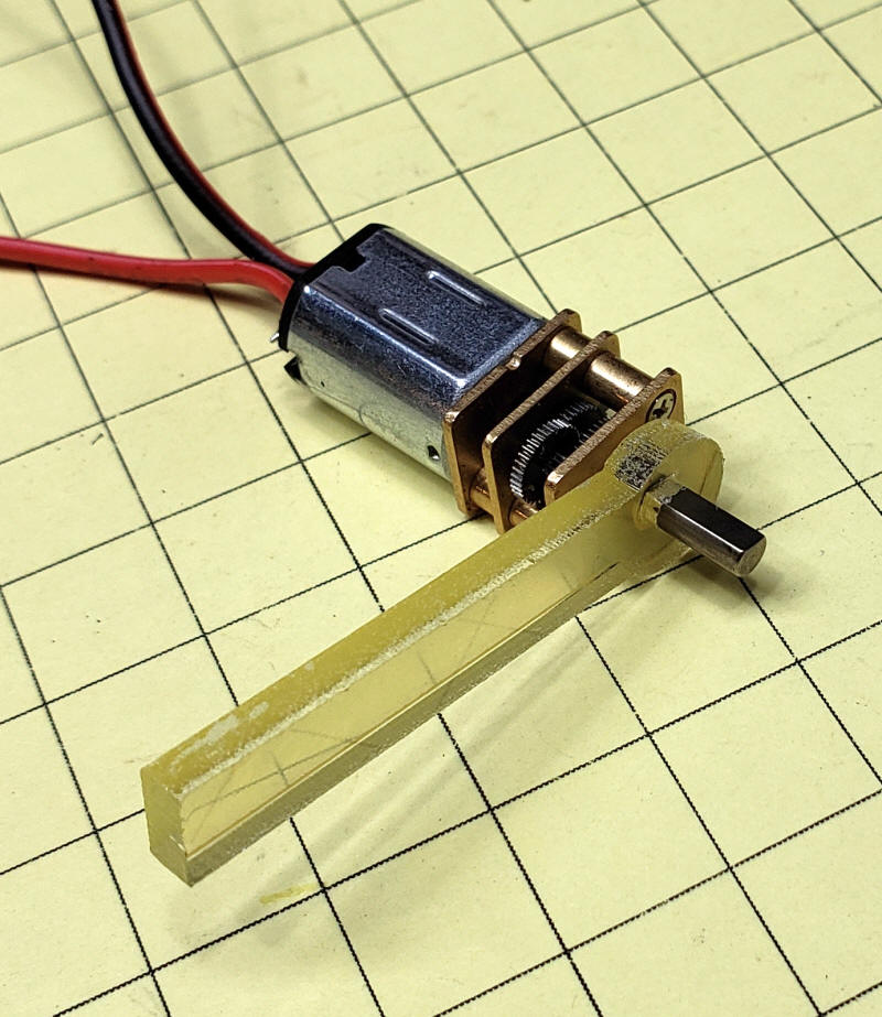
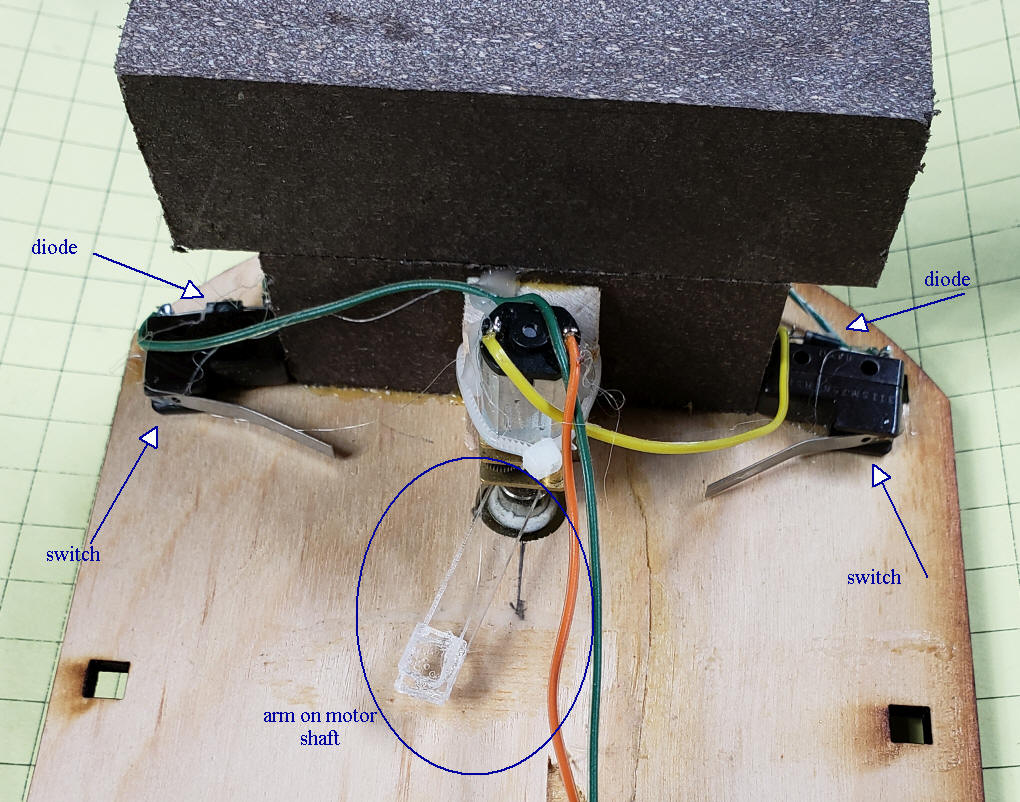
| Limit Switches To get the motor to stop and start at the right point some sort of switch would be needed at each extreme of its rotation. I added a small plastic arm to the base of the motor's shaft. It has a flat spot in the hole that fits the motor that will keep it from slipping.
A micoswitch was placed at each end of the arm's rotation so that it would be turned on when the arm hit it. The switches that I used are SPDT (Single Pole Double Throw) switches. They are available from eBay, Amazon and other sources. The switches were wired so that the motor would turn off when the arm hit the switch. The schematic of the switches has the normally closed (NC) terminal at the top, the common in the center and the normally open (NO) terminal at the bottom. As the diagram shows there is a complete circuit since both of the normally closed terminals carry current to the motor. As soon as the arm on the motor hits one of the limit switches the normally closed terminal opens stopping the motor.
This circuit is simple and works great with one exception, once the motor is stopped at either end of its rotation it will not start back up as the circuit is broken. |
| Diodes to the Rescue! Since this trolley works on DC adding a 1 amp diode to each microswitch gives us exactly what we need, but why? Diodes, as you may know, only allow an electrical current to flow in one direction. They are oriented on the micro switches so that current does not flow when the switch is first turned off. When the voltage is reversed, bringing the trolley back to life, the diode conducts and the motor turns back on rotating in the other direction. The goal is to have the motor start up and rotate the conductor in the opposite direction when the polarity of the DC power from the track is reversed. To accomplish this a diode is added to each switch as shown here. It is important that the diodes be oriented as shown so that the power will be broken when the polarity is in one direction but conducts and moves the motor when the polarity switches.
This photo shows a test setup that has two switches, two diodes, a motor and an arm that hits the switch levers at either extreme of movement.
|
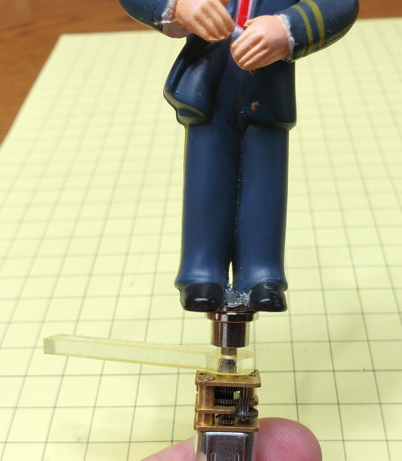
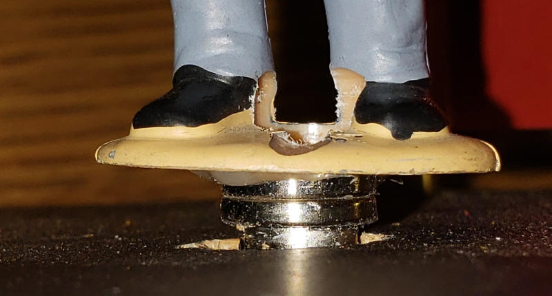
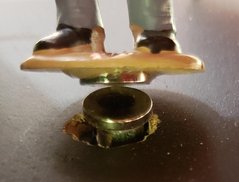
| Attaching the Conductors I experimented with several ways of attaching the base of each conductor to the motor's shaft and settled on using small rare earth magnets (available from Amazon ) ) One was glued to the conductor's feet and the other was glued to a Dubro Collar (available from Amazon ) ) that was attached to the motor shaft.
|
| Conclusion I am sure that there other ways that the conductor's could be rotated but this method works well and will, hopefully, give years of service. |