|
.JPG) |
|
Sensor Options
-
The sensors for the MSTS are made up of a pair of infrared LEDs and a pair of
infrared detectors. As mentioned earlier, the IR LEDs are pulsed at a
frequency of 38 KHz and the detectors only respond to IR at that frequency.
-
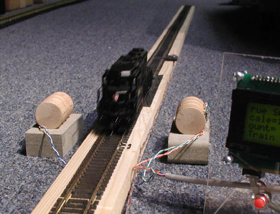
The MSTS comes with one set of sensors that are mounted
in a clear, plastic "U" shaped bracket. This mounting method allows
users to place the sensors over the track so that they can easily be moved
from place to place on the layout or to another layout entirely. This is
shown in the photo at the top of this page.
-
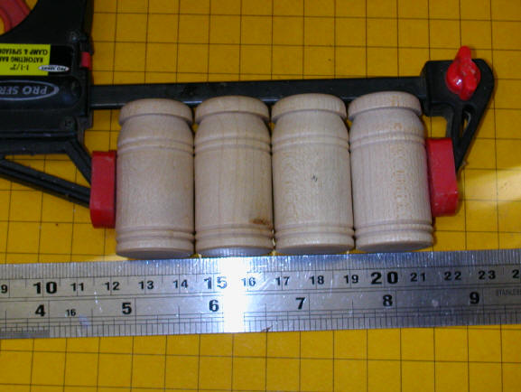
The
sensors can be mounted in any number of trackside scenery items. The
photos below show two "G" scale installations, one inside of two wooden
barrels and the other inside of piles of railroad ties.
.JPG)
|
|
This photo shows the indicator LEDs that light red when the
IR emitters and detectors are properly aligned.
.JPG)
|
|
Mount Your Own Sensors
A package consisting of two IR LEDs, two red
indicator LEDs, 4 current limiting resistors, two 38 KHz IR detectors, one
filter capacitor and a connecting cable that is terminated in an RJ-12 plug that
fits into the Speedometer board is available for those of you who would like to
mount your own sensors in a building, or other track-side piece of scenery
|
|
To mount your own follow these steps:
|
|
|
|
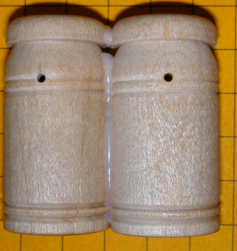
IR EMITTER CONSTRUCTION
.
-
To mount the LEDs drill two 1/16" holes in
your object, 1" apart. These holes will allow the LED "light" to exit.
If you have difficulty drilling small holes you can drill larger holes and place
small pieces of brass tubing with a 1/16" inside diameter in them. The
important thing is that the amount of IR that is permitted to escape is limited
to what can pass through a hole no larger than 1/16".
-
Wiring is very simple. The remaining
ends of the two resistors are connected together and the two negative leads of
the LEDs are also connected together. If you have difficulty identifying
the leads, the longer one is positive and the negative one is next to the flat
spot on the side of the LED's base. You must take care that the two leads
of the LEDs don't touch and short out. Bending them as in the photo helps
to keep this from happening.
-
Solder the two resistors and the two negative
leads together. Solder wires to each connection as below.
-
Solder a two conductor length of insulated
wire to the points shown below. The wire needs to be long enough to extend
under the track, or under your layout, to the sensor unit across from it.
|
|
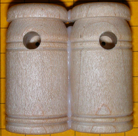
IR DETECTOR CONSTRUCTION
-
The sensors are mounted in much the same way
as the IR LEDs shown above.
-
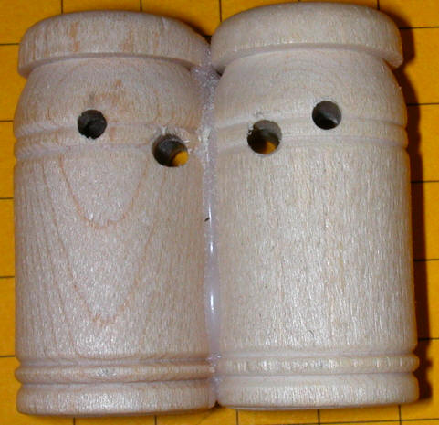
Start by drilling another pair of 1/16" holes,
spaced exactly 1" apart, in the other set of cans.
-
Increase the size of the back of these
holes, shown below, to 3/16" to accommodate the lens that protrudes from the
front of the IR sensors
-
-
Note the other two holes. They are
3/16" and are for the indicator LEDs.
-
-
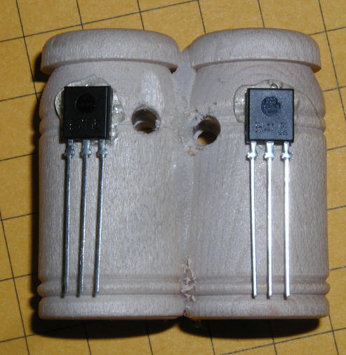
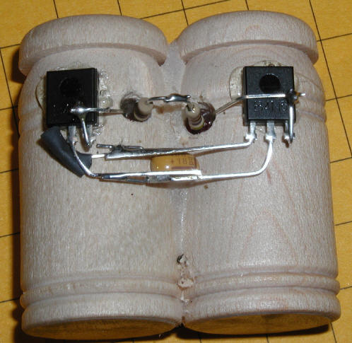
Glue the sensors to the backs of the
drilled cans as below.
-
-
-
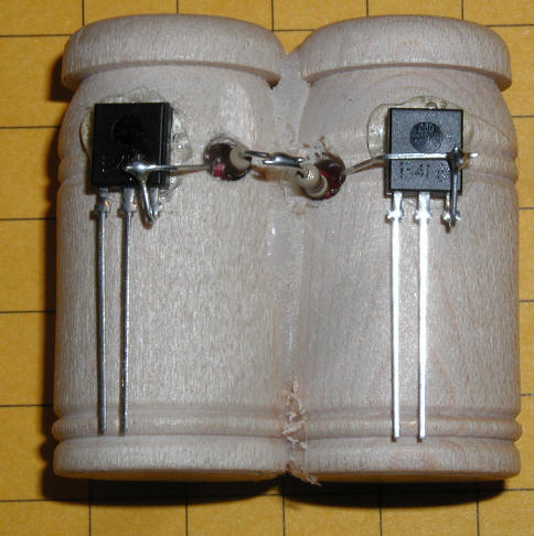
Solder one of the 470 ohm resistors to
each of the indicator LEDs as you did with the IR LEDs in the first section.
-
Insert one of the LEDs into each hole
taking care that the leads do not touch. Solder the two resistors
together as below. The other LED leads are soldered to the output pins
on the sensors.
-
-
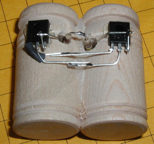
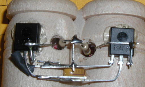
Carefully solder the other leads from the
sensors as below. Note that a small piece of insulating tubing is used
to keep the outer lead from the left sensor from shorting against the inner
lead.
-
-
Carefully trim the leads from the
capacitor to 1/4". Place the capacitor under the two power leads as
shown below. Note that one of the capacitor's leads is marked with a
"+". This lead MUST connect to the lower of the center leads of the
sensors.
-
-
Here is a close-up.
-
-
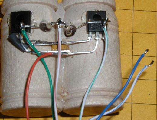
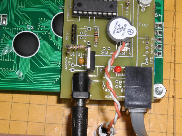
Connect the wires from the RJ-12 cable as
shown below. The ORANGE wire goes to the negative, center, lead on the
sensors. The ORANGE/WHITE striped wire goes to the joint where the two
LED resistors join. The GREEN wire goes to the right lead on the left
sensor and the GREEN/WHITE lead goes to the right lead on the right sensor.
The BLUE and BLUE/WHITE wires will go to the IR LEDs.
-
-
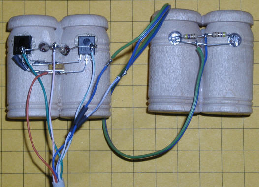
Connect the BLUE wire from the RJ-12 to
the wire that goes to the negative leads on the IR LEDs. The
BLUE/WHITE wire goes to the connection to the two resistors as show below.
Use tape or heat shrink tubing to insulate the joints.
-
-
|
|
Custom Sensors
Custom sensor mounting is available. Due
to the time involved in making and testing custom sensors the price is based on
time and materials. The price for the sensors, wiring and other parts is
in the price list. Most custom sensor installation takes between 1 and 2
hours which is billed at $30.00 per hour.
|
| |
| |
| |
| |