|
The wireless speedometer sensor is normally installed in a small Hartland
gondola car. The sensor can be installed in any other car for an
additional fee. This section gives details on how such an installation
was made in a USA Trains Hopper Car. |
|
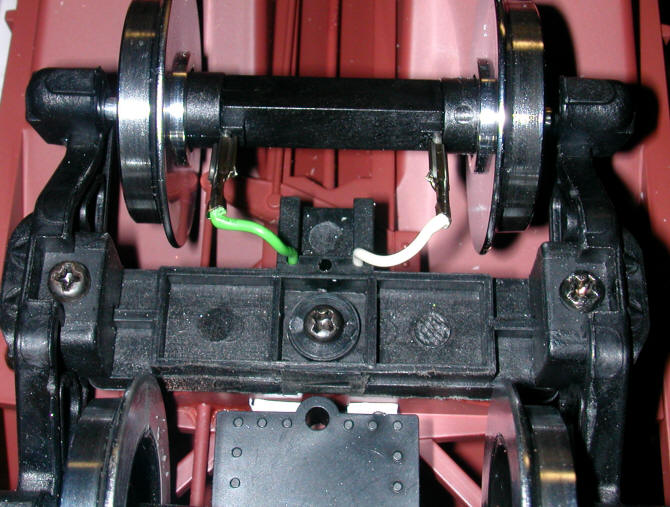
The IR sensor unit is installed on the underside of the truck.
Wires are run through existing holes into the hopper's interior.
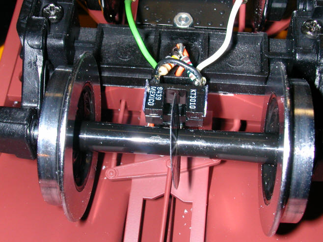
In the photo below you can see that LGB ball bearing wheels with power takeoffs
on the right. They will be used to monitor the track voltage so that it
can be included in packet that is sent wirelessly to the receiving unit.
 |
|
 |
|
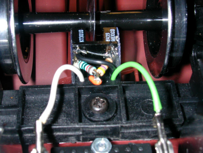
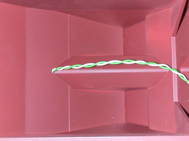
The other truck has one ball bearing wheel set.
The wires from the power takeoff enter the hopper.
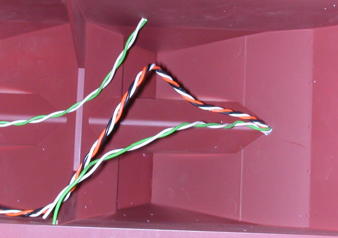
The wires from the sensor and the other power takeoff enter the
other end of the hopper.
 |
|
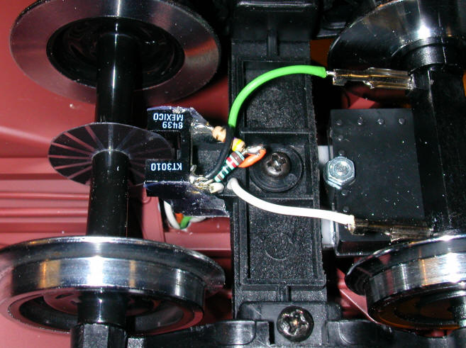
This installation is designed to transmit track voltage along with speed.
A bridge rectifier and 0.1 mfd tantalum capacitor are added to send a clean
voltage to the transmitter. That unit can be seen here.

The green / white wires come from the two power trucks. The capacitor
is needed to smooth the voltage output a bit. Without it the voltage jumps
all over.
Please note that the voltage reported by the unit will be 0.7 volts lower
than the actual track voltage. This is due to the voltage drop across the
bridge rectifier. |
|
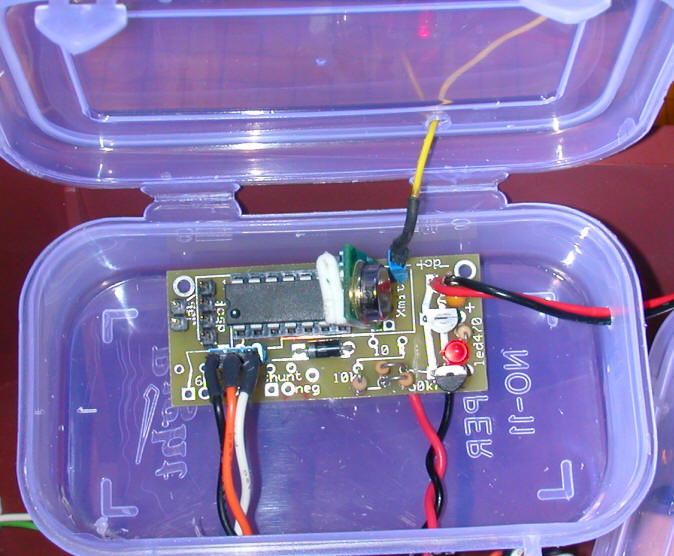
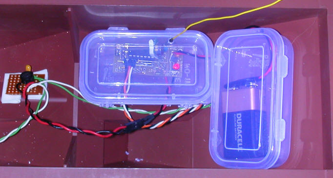
A somewhat secure environment is provided for the transmitter by
housing it in a plastic box. The three wires in the lower left (black,
orange, white) are from the speed sensor. Note that they MUST be plugged
in with this orientation.
The yellow wire in the upper right is the transmitter's antenna.
It plugs into the blue receptacle on the board. The red/black pair of
wires in the upper right go to the 9 volt battery. Those in the lower
right go to the bridge rectifier that supplies track voltage.
 |
|
The battery is also secured in a plastic box. A power
switch has not been added in this photo.
The connection between the transmitter and the bridge rectifier
is show below the transmitter box. Please make sure that the wires are
connected red-to-red and black-to-black.
 |
|
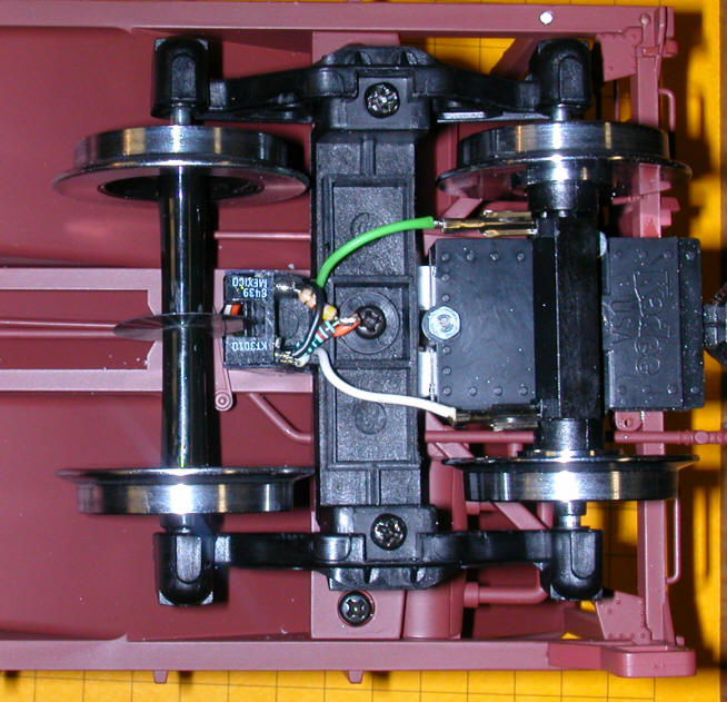
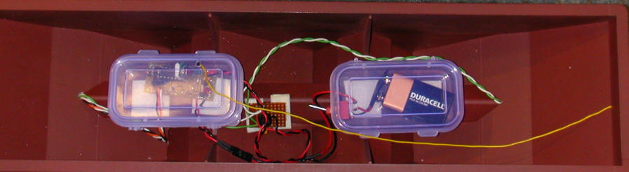
This is the completed hopper with the transmitter (left) and battery (right) in
boxes. The bridge rectifier is in the center. The yellow wire is the
antenna. Ideally it should be vertical for maximum range but it gives
acceptable performance when horizontal and under the car's load.
 |
|
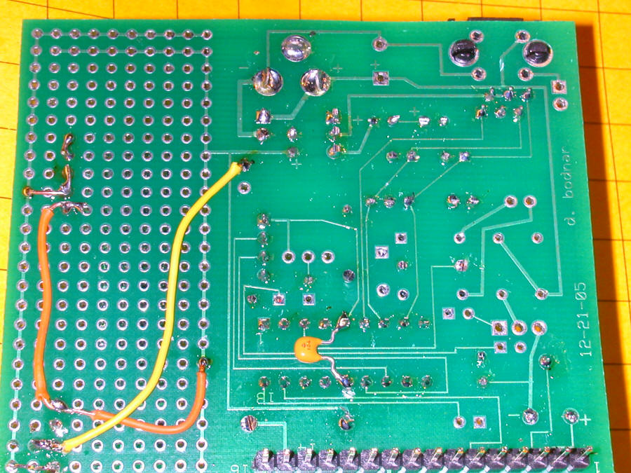
This is a view of the circuit modification that was necessary to have
the wireless receiver work with the wired sensors still plugged in.
 |
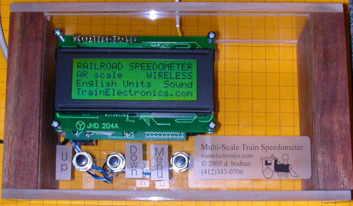
| This view shows the back of the unit. Note the
notch in the plastic (lower left) to permit the sensor and power cables
to exit.
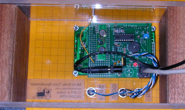 |
| The front view shows the receiving antenna (white tube at
the top) exiting the box. There is ample room in the box for
battery operation.
|
| |