Precise Camera Panning
With Stepper Motors

Revised 10-29-11

(click on image below to see full panoramic view)

The objective of this project is to design and construct a controller that will operate a geared stepper motor that will rotate (pan) a digital camera to facilitate taking wide area panoramic photos.
The movement of the camera will be very precise and repeatable as the stepper motor moves 1/10th of 1 degree per step.  In other words it takes 3600 steps to rotate through a 360 degree circle.
The stepper motor's operation will be controlled by a standard TV remote control that will also trigger the camera to take a photo.

The original design used a camera that could be triggered to take a photo electronically.  Although this works well it limits the number of cameras that can be used.  The shutter trigger mechanism has been redesigned to allow use with nearly any camera.  The shutter button can be automatically pushed by a tiny electromechanical device called a servo.  Click here for more information on the new shutter release.

Click here to see sample images


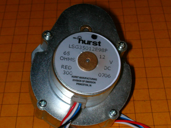
Hardware:

The stepper motor is a 6 wire unipolar stepper manufactured by Hurst. It is part LSG35012E98P and sells for about $70.00.

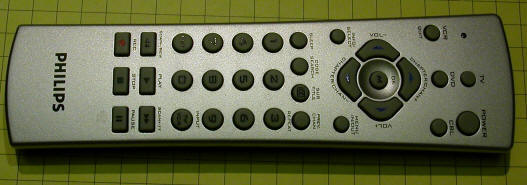
The motor is controlled by a TI SN754410NE H-Bridge that is connected to a PIC 16fF88 microcontroller.

The PIC sends pulses to the H-Bridge that move the motor in 1/10th degree/step increments in either a clockwise or counter clockwise direction.

A 4 line by 20 character LCD display is used to show operational parameters and to facilitate changing settings.  All adjustments and control input are done with a standard TV remote control utilizing Sony IR codes.

The digital camera is a Canon Elph from the PowerShot series.  It can take a photograph under control of the PIC 16F88 thanks to the excellent work done by the folks at the CHDK Wiki.  They have developed a set of programs and scripts that provide many updated and expanded capabilities to the PowerShot series of cameras.  The one that is used in this project is a USB Remote Cable that allows you to trigger the camera and take a photograph by pulling a pin on the PIC high for a moment.

Schematic:

Note: this schematic is for the revised circuit board described below.


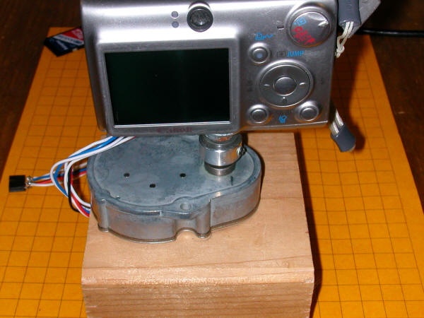
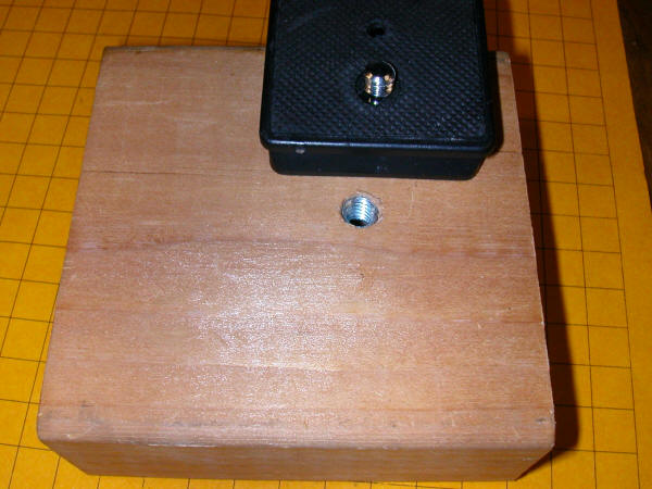
Prototype Photos

This photo shows the wood block that connects the stepper motor to the tripod, the motor and the camera.

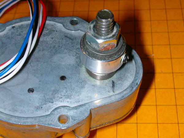
The camera mounts to an appropriately threaded bolt attached to the stepper motor.

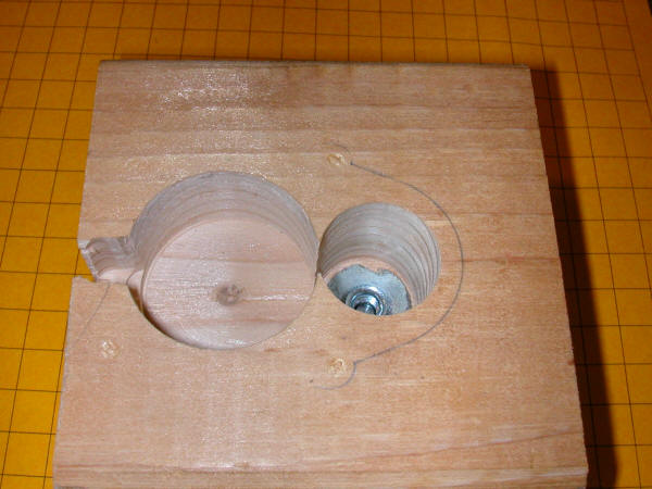
The hole one the left accepts the stepper motor.  The one at the right is for a "T" nut that connects to the tripod mount.

This is the bottom of the adapter showing the other end of the "T" nut and the tripod mount that will thread into it.


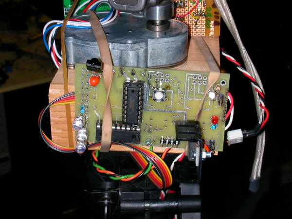
The stepper motor is mounted to a short piece of wood cut from a 2X4 and can be seen at the top of this photo.  The main circuit board is in the front.

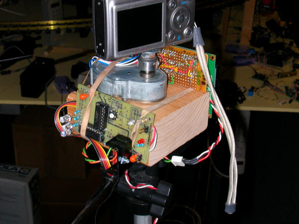
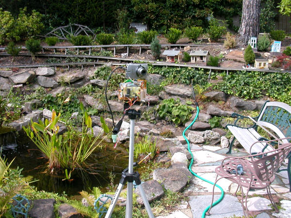
In this wider shot you can see the camera mounted on the stepper motor.  The whole thing is sitting on a tripod.

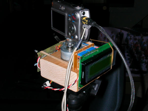
In this photo you can see the LCD display and the USB cable that is used to trigger the camera to take a photo.

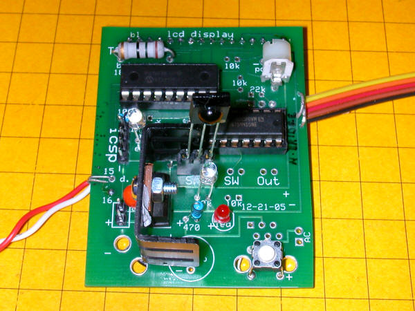
Revised Circuit Board

The prototype circuit board used an external LCD display that received commands via an RS-232 interface.  Although it worked well programming it was cumbersome.  For this reason the circuit board was revised so that it would support a directly attached LCD display.

The display connects to the header at the top, the IR detector is the raised component in the center.  The reset button is in the lower right.

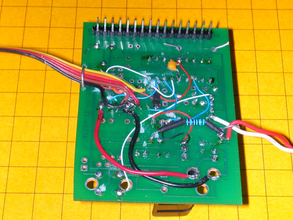
This view of the back of the board shows the LCD connector more clearly.  It also shows the amount of rewiring that was necessary to repurpose the circuit board which was designed for another project.

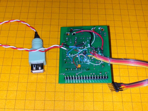
The plug in the lower right goes to the 6 pin stepper motor cable.  The USB plug at the left goes to the Canon camera's USB connection via the connecting cable that came with the camera.

Setup
  • Connect the Stepper motor to the rainbow cable from the circuit board
  • Connect one end of the USB cable to the USB connector coming from the board.  Plug the other end into the USB connection on the camera
  • Connect the circuit board to 12 volts DC
  • Turn on the camera making sure that the script for USB remote control is active
  • Level the mount on the tripod
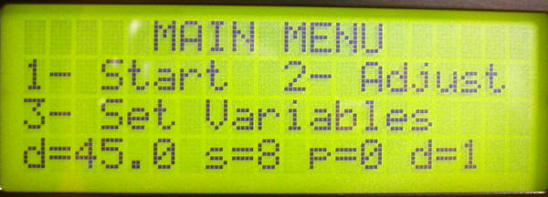
Operation

When power is applied the copyright screen is displayed.  A short time later the Main Menu appears.

Pressing 1 on the TV remote starts shooting, 2 allows you to adjust the position of the camera and 3 lets you change variable values.  Note the that variables are shown in line 4:  d=Degrees, s=Steps, p=Pause before / after shot and c=0 for clockwise and c=1 for counterclockwise.

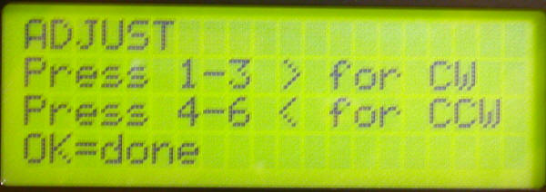
To adjust the camera a bit left or right press 1 (1 degree steps), 2 (5 degree steps), 3 (10 deg.) or > (whatever your degree setting is for)
Similarly press 4, 5, 6 or < for adjustments to the left.  Press OK when done.

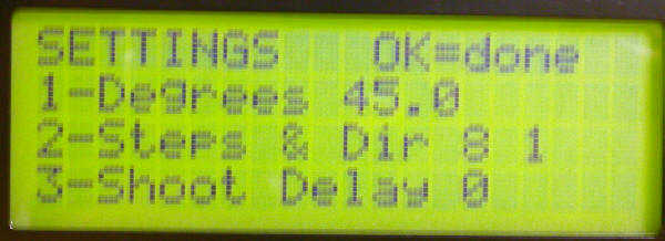
The setting screen allows you to change the variables in the program.  Pressing 1 allows you to enter a 4 digit number of degrees X 10.  That means to enter 0450 for 45 degrees or 0225 for 22.5 degrees.

The shots setting is a 4 digit number that is the number of shots to be taken in the sequence.

The Shoot delay is the pause time before and after a shot is taken.  It allows any motion of the tripod to settle and also allows for time exposures.  It is a 2 digit number in seconds.  If you enter 10 the system will pause for 1/2 of the time (5 seconds) before shooting and an additional 5 seconds after shooting..

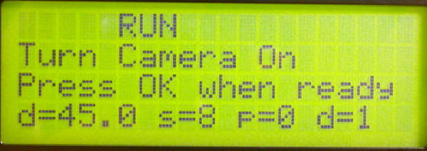
When you select Start this menu appears.,  Ready the camera and press the OK button on the TV remote.

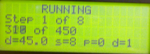
While running the display shows the number of the shot it is on and the number of steps (in 1/10th of a degree) that the camera has moved.


Software - revision 09-12-08:
'9-12-2008  version 3-5         - WORKS
'on green speedo board with H-bridge
'works properly with 6 wire stepper (old hard drive?)
'working well with Hurst motor - 3600 steps per revolution rather than 
' advertised 14400 - four steps per pulse, I would guess
' needs pause in "step 1" routine to develop proper torque
INCLUDE "modedefs.bas"
cmcon=7                 'allows you to use pins as digital rather than analog
ansel=0                 'allows you to use pins as digital rather than analog
  @ DEVICE  PIC16F88, INTRC_OSC_NOCLKOUT, WDT_OFF, LVP_OFF, PWRT_ON, PROTECT_ON, BOD_ON  
DEFINE OSC 8
OSCCON = %01100111      'MUST BE USED to set clock speed   =$67 = 4mhz
DEFINE LCD_DREG     PORTB 'pins 9-12 on PIC with next item set to "4"
DEFINE LCD_DBIT     4       'change to 4 to use top 4 bits (pins 4-7 rather than 0-3)
DEFINE LCD_RSREG    PORTA  
DEFINE LCD_RSBIT    1       'pin 18 on PIC with PORTA set
DEFINE LCD_EREG     PORTA  
DEFINE LCD_EBIT     0      'pin 17 on PIC with PORTA set 
p_len               VAR BYTE
loop                VAR BYTE
temp0               VAR BYTE
temp                VAR WORD
temp1               VAR WORD
temp2               VAR WORD
temp3               VAR BYTE
temp4               VAR WORD
temp5               VAR WORD
temp6               VAR BYTE
digit               VAR BYTE
PauseWord           VAR WORD
TempWord            VAR WORD
TempWord2           VAR WORD
value               VAR BYTE
LED                 VAR porta.2    'also high 10
StartSwitch         VAR porta.5     'pin 2
CameraTrigger       VAR porta.7     'pin 16 - pull high to trigger camera
CW                  VAR BIT         'CW if 1, CCW if 0
CW_CCW              VAR BIT         'stores what was done last

line1               CON 128
line2               CON 192
line3               CON 148
line4               CON 212

zero                CON 136
one                 CON 128
two                 CON 129
three               CON 130
four                CON 131
five                CON 132
six                 CON 133
seven               CON 134
eight               CON 135
nine                CON 136
channelUP           CON 144
channelDOWN         CON 145
volumeUP            CON 146
volumeDOWN          CON 147
OK                  CON 148
Menu                CON 224
ENTER               CON 139
Degrees             VAR WORD    'degrees (steps actually) to move each time
NumberOfSteps       VAR WORD    'number of times to do the rotate
ShootSeconds        VAR BYTE    'pause after completed rotate before shot
CWorCCW             VAR BIT     '0=cw, 1=ccw
x                   VAR BYTE
steps               VAR WORD 
stepArray           VAR BYTE(4)
serial_out          VAR porta.3
vwhole              VAR BYTE
vdecimal            VAR BYTE
vwhole=3
vdecimal=7
stepArray[0] = %00001010      '10
stepArray[1] = %00000110      '6
stepArray[2] = %00000101      '5
stepArray[3] = %00001001      '9
TRISb = %11110000
IRpulse_length VAR WORD(13)
xx VAR BYTE
Command VAR BYTE
IRin                VAR porta.4 'pin 15
'ansel = 0
'cmcon0 = 7
trisa.4=0           'make leds output
trisa.5=1
trisb.5=0
trisa.2=1           'start button input
trisa.4=1           'IR input
trisa.3=0
trisa.7=0           'camera trigger
LOW CameraTrigger
LOW portb.0:LOW portb.1:LOW portb.2:LOW portb.3      'relax stepper
DATA @0, 1, 194, 0, 8, 1, 1  ' "1, 194"=450 steps=45 deg; 8 steps, 2 sec pause , cw
READ 0,temp
READ 1, temp1
Degrees = temp*256
Degrees=Degrees + temp1
READ 2, temp
READ 3, temp1
numberofsteps =temp*256
numberofsteps=numberofsteps+temp1
READ 4, shootseconds
READ 5, CWorCCW

PAUSE 200			'let LCD unit wake up      
LCDOUT $fe,1,$fe, line1+1,"Camera Controller"    
LCDOUT  $fe, line2+4,"Version " ,#vwhole,".",#Vdecimal
LCDOUT  $fe,line3," (c) d.bodnar 2008"  
GOSUB lastline:

PAUSE 1500

MenuTop:
LOW portb.0:LOW portb.1:LOW portb.2:LOW portb.3      'relax stepper
LCDOUT  $fe,1,$fe,line1+5,"MAIN MENU"
LCDOUT  $fe, line2,"1- Start  2- Adjust"
LCDOUT $fe, line3,"3- Set Variables"
GOSUB lastline:
Command=0
GOSUB GetIR 
IF Command =    one THEN RunSequence
IF Command =    two THEN Adjust
IF Command =    three THEN SetTimers
GOTO MenuTop:

Adjust:
LCDOUT  $fe,1,$fe,line1,"ADJUST"
LCDOUT  $fe, line2,"Press 1-3 > for CW"
LCDOUT $fe, line3,"Press 4-6 < for CCW"
LCDOUT $fe, line4,"OK=done "
Command=0
GOSUB GetIR 

IF Command =    one THEN CWone:
IF Command =    two THEN CWfive:
IF Command =    three THEN CWten:
IF Command =    four THEN CCWone:
IF Command =    five THEN CCWfive:
IF Command =    six THEN CCWten:
IF Command =    volumeUP THEN DegreesAdjustCW    
IF Command =    volumeDOWN THEN DegreesAdjustCCW
IF Command = OK THEN menutop 
GOTO adjust
DegreesAdjustCW:
  FOR temp5=1 TO Degrees   
    LCDOUT  $fe, line4,#temp5," of ",#Degrees," "
    CW=1
    GOSUB step1
  NEXT temp5 
GOTO adjust:

DegreesAdjustCCW:
  FOR temp5=1 TO Degrees   
    LCDOUT  $fe, line4,#temp5," of ",#Degrees," "
    CW=0
    GOSUB step1
  NEXT temp5 
GOTO adjust:

SetTimers:
LCDOUT  $fe,1,$fe,line1,"SETTINGS   OK=done"
LCDOUT  $fe, line2,"1-Degrees ",#(Degrees/10),".",#Degrees DIG 0
LCDOUT $fe, line3,"2-Steps & Dir ",#numberofsteps," ",#CWorCCW
LCDOUT $fe, line4,"3-Shoot Delay ",#shootseconds
Command=0
GOSUB GetIR 

IF Command =    one THEN SetDegrees
IF Command =    two THEN SetStepsDirection
IF Command =    three THEN SetShootDelay
IF Command = OK THEN menutop
GOTO settimers:

SetDegrees:
LCDOUT  $fe,1,$fe,line1+5,"SET DEGREES"
LCDOUT  $fe, line2,"Enter 4 digits for"
LCDOUT $fe, line3,"Degrees x 10"
LCDOUT $fe, line4," "
digit=4
GOSUB GetNumber:
Degrees=PauseWord
WRITE 0, Degrees / 256
WRITE 1, (Degrees-(Degrees/256)*256)
GOTO SetTimers

SetStepsDirection:
LCDOUT  $fe,1,$fe,line1+5,"SET STEPS"
LCDOUT  $fe, line2,"Enter 4 digits for"
LCDOUT $fe, line3,"Steps between shots"
LCDOUT $fe, line4," "
digit=4
GOSUB GetNumber:
numberofsteps=PauseWord
WRITE 2, numberofsteps / 256
WRITE 3, (numberofsteps-(numberofsteps/256)*256)
LCDOUT  $fe,1,$fe,line1+5,"SET DIRECTION"
LCDOUT  $fe, line2,"1- Clockwise"
LCDOUT  $fe, line3,"2- Counter Clockwise"
LoopBack:
Command=0
GOSUB GetIR 
IF Command =    one THEN 
    CWorCCW=0
    GOTO settimers
ENDIF
IF Command =    two THEN 
    CWorCCW=1
    GOTO settimers
ENDIF    
WRITE 4, CWorCCW
GOTO loopback:

SetShootDelay
LCDOUT  $fe,1,$fe,line1+5,"SET DELAY"
LCDOUT  $fe, line2,"Enter 2 digits for"
LCDOUT $fe, line3,"Camera pause"
LCDOUT $fe, line4," "
digit=2
GOSUB GetNumber:
shootseconds=PauseWord
WRITE 5, shootseconds
GOTO SetTimers

RunSequence:
LCDOUT  $fe,1,$fe,line1+5,"RUN"
LCDOUT  $fe, line2,"Turn Camera On"
LCDOUT $fe, line3,"Press OK when ready"
GOSUB lastline:
Command=0:GOSUB getir 
IF Command<>OK THEN runsequence
LCDOUT  $fe,1,$fe,line1+5,"RUNNING"
LCDOUT  $fe, line2," "
LCDOUT $fe, line3," "
GOSUB lastline:

FOR temp=1 TO numberofsteps
LCDOUT  $fe, line2,"Step ",#temp," of ",#numberofsteps
  FOR temp5=1 TO Degrees   
    LCDOUT  $fe, line3,#temp5," of ",#Degrees," "
    IF CWorCCW=0 THEN
        CW=1
        GOSUB step1
    ELSE
        CW=0
        GOSUB step1
    ENDIF
  NEXT temp5   
    PAUSE shootseconds*500
    HIGH CameraTrigger
    PAUSE 100
    LOW CameraTrigger
    PAUSE shootseconds*500
NEXT temp

GOTO menutop:

CWone:
    CW=1
    GOSUB step1
    PAUSE 100
GOTO adjust

CWfive:
    CW=1
    FOR temp3=1 TO 5
        GOSUB step1:
    NEXT temp3
    PAUSE 100
GOTO adjust

CWten:
    CW=1
    FOR temp3=1 TO 10
        GOSUB step1:
    NEXT temp3
    PAUSE 100
GOTO adjust

CCWone:
    CW=0
    GOSUB step1   
    PAUSE 100
GOTO adjust

CCWfive:
    CW=0
    FOR temp3=1 TO 5
        GOSUB step1:
    NEXT temp3    
    PAUSE 100
GOTO adjust

CCWten:
    CW=0
    FOR temp3=1 TO 10
        GOSUB step1:
    NEXT temp3    
    PAUSE 100
GOTO adjust

GetIR:
LOW led
p_len=100
Getstartbits:
PULSIN IRin ,0,IRpulse_length(0)
IF IRpulse_length(0) < 200 THEN        'was 200 for 4 mhz clock
RETURN
ENDIF
FOR xx=1 TO 12
PULSIN IRin,0,IRpulse_length(xx)
NEXT xx
displaybits:
IF IRpulse_length(1) < p_len THEN     'was 100 for 4 mhz clock
    Command.Bit0 = 0 
    ELSE 
    Command.Bit0 = 1
ENDIF
IF IRpulse_length(2) < p_len THEN
    Command.Bit1 = 0
    ELSE
    Command.Bit1 = 1
ENDIF
IF IRpulse_length(3) < p_len THEN
    Command.Bit2 = 0
    ELSE
    Command.Bit2 = 1
ENDIF
IF IRpulse_length(4) < p_len THEN
    Command.Bit3 = 0
    ELSE
    Command.Bit3 = 1
ENDIF
IF IRpulse_length(5) < p_len THEN
    Command.Bit4 = 0
    ELSE
    Command.Bit4 = 1
ENDIF
IF IRpulse_length(6) < p_len THEN
    Command.Bit5 = 0
    ELSE
    Command.Bit5 = 1
ENDIF
IF IRpulse_length(7) < p_len THEN
    Command.Bit6 = 0
    ELSE
    Command.Bit6 = 1
ENDIF
IF IRpulse_length(8) < p_len THEN
    Command.Bit7 = 0
    ELSE
    Command.Bit7 = 1
ENDIF
IF Command.Bit7 = 0 THEN 'Bit 7 is one of the device bits
    Command = Command + 1
ENDIF                                                                     
IF Command = 10 THEN
    Command = 0
ENDIF
RETURN 

GetNumber:  
Command=0
PAUSE 200
PauseWord=0
GetRevSettings2:
GOSUB getir
IF Command=0 THEN GetRevSettings2
IF Command > 137 OR Command < 128 AND Command <>139 AND Command <> 0 THEN 
    RETURN	'abort on non number 0-9
ENDIF
'if command=139 then GetRevSettings0
value=Command-127
IF value = 10 THEN value=0
PauseWord=PauseWord*10+value
digit=digit-1
LCDOUT $fe, line4,#PauseWord,"    "
IF digit =2 AND PauseWord=0 THEN LCDOUT $fe,line4,"0",#PauseWord
IF digit =1 AND PauseWord=0 THEN LCDOUT $fe,line4,"00",#PauseWord
PAUSE 100:Command=0
IF digit=0 THEN 
    temp0= PauseWord / 256
    RETURN
ENDIF
GOTO GetRevSettings2

Step1:
    FOR temp0=1 TO 4
        IF CW = 1 THEN
            steps = steps + 1
        ELSE
            steps = steps - 1
        ENDIF
      portb = stepArray[steps //4] 

       PAUSE   2    '2 seems to be a minimum
    NEXT temp0     
    TOGGLE led:'high led:pause 1:low led
    skipout:
RETURN  

lastline:
LCDOUT $fe, line4,"d=",#(Degrees/10),".",#Degrees DIG 0," s=", #numberofsteps," p=",#shootseconds," d=",#CWorCCW
RETURN

Sample Images

There are three sets of sample images that were taken from the top of the back yard steps. The stepper motor was rotated 450 steps (45 degrees) between shots.  Each set of photos makes up one 360 degree set of images.

 The panning device was mounted on top of a tripod and leveled

.

Two of the sets of sample photos were taken with the panning unit moving in a clockwise direction and one set was taken moving in a counter clockwise direction.

If you look carefully you will note that there is overlap between each image.

The images are quite large (3 to 4 meg each) - the pages load slowly.  The images display at a width of 600 pixels to make viewing easier - to see the full sized image right click on it and select "view image"

Click here for sample images 1

Click here for sample images 2

Click here for sample images 3