Aristo-Craft
REVOLUTION Servo Interface
d. bodnar - revised 06-04-11
Introduction
I have been working with Aristo-Craft on the development of the REVOLUTION radio control
system since November of 2006. During that time the
REVOLUTION has matured into a full featured, reliable and robust system for controlling our
trains that has been adopted by many, many model railroaders.
There is, however, one thing that it does not do that keeps one group of garden railroaders from using the REVOLUTION: there is no built-in capability to control a servo. As you may know, servos are small geared motors that are commonly used to move the control surfaces, steering arms and throttles on radio control model airplanes, boats and cars.
This lack of servo capability keeps the REVOLUTION from being used to control live steam locomotives and other vehicles or accessories that require that some lever or arm be physically moved to and held at a particular position. There is more information about servos on my web page at: http://www.trainelectronics.com/Animation_servos/index.htm .
This issue first came to my attention when a gentleman posted a question on the Aristo-Craft forum. He had tested the REVOLUTION receiver to control the speed of a Jersey City G Scale Tug Boat. It worked well with the electric motor but he could not use the system to steer the boat as there was no way to operate a servo that was connected to the tug boat's rudder.
I saw his post and gave his problem some thought. My response was that using the REVOLUTION to control a servo certainly was doable and it could be accomplished by creating a microcontroller based interface between one or several of the six auxiliary control buttons on the transmitter and one or two servos. You may recall that there are six auxiliary outputs available on the REVOLUTION that are normally used to control a smoke unit or sound card. These are numbers 1 through 6 on the keypad.
What follows is a detailed look inside of the development and creation of the REVOLUTION Servo Interface, an accessory that allows the REVOLUTION to be embraced by virtually all garden railroaders.
First Prototype
The Servo Interface started as a simple device that would use button 1 on
the REVOLUTION transmitter to move a servo's arm to the left (counterclockwise), button 2 to move the arm to the center position and button 3 to move
the arm to the right (clockwise). A second servo could be added that would
be controlled in a similar fashion with buttons 4, 5 and 6.
I quickly discovered that what I had hoped would be a simple device with simple software would need some specialized features to deal with the way that the REVOLUTION reacted when a button was pushed on the transmitter. The problem that I ran into stems from the fact that each button push on the REVOLUTION's transmitter turns on the corresponding auxiliary output on the receiver for not just a moment, as I had hoped and as the setting "momentary" implies, but for nearly a full second. This might not sound like much of an issue but it makes precise control over the position of a servo's arm problematic.
I dealt with that situation by programming two servo movement speeds into the microcontroller. When a button is pressed only once or for just a brief time the servo arm rotates only about 1 degree. If the button is held down for more than 2 seconds the arm begins to move more rapidly. This two-speed control allows the servo's arm to be placed with reasonably good precision, certainly within a degree or two while allowing you to move the servo arm rapidly should that need arise.
A "proof of concept" unit was built and programmed as described above. It worked well but a number of things were missing.
Needed: A Real User Interface
In order to make this a flexible and full-featured unit I felt that the end user had to
be given the ability to fine tune the operation of the servo interface to meet
his or her needs. Things like limits on how far the servo arm could move
to the left or right and the speed with which movements took place needed to be controlled.
Ideally this configuration would be done within the user interface on the REVOLUTION transmitter itself. Unfortunately I had to design the interface so that it could interact with the REVOLUTION using only the functions and functionality that was currently installed in the REVOLUTION transmitter limiting me to the use of the six auxiliary input buttons.
I considered adding a few buttons and potentiometers to the servo interface board but hit on what I think is a much more elegant, capable and user-friendly solution. I had recently developed a plug-and-play auto-reversing controller for Aristo-Craft's new PCC trolley. All speed control and configuration on that unit was done with a basic hand held infrared TV remote control unit.
I decided to give that method of configuration a try on the servo interface. As you are about to see it worked out very well!
Hardware
The Servo Interface comes in two functionally identical but physically
different styles. The first uses traditional "through hole" components.
Through hole means that the leads on the devices on the board go into holes on
the circuit board and are soldered to the board from the back. The other
style uses "surface mount" devices. These components, as their name
implies, are soldered directly to the top or bottom surface of the circuit
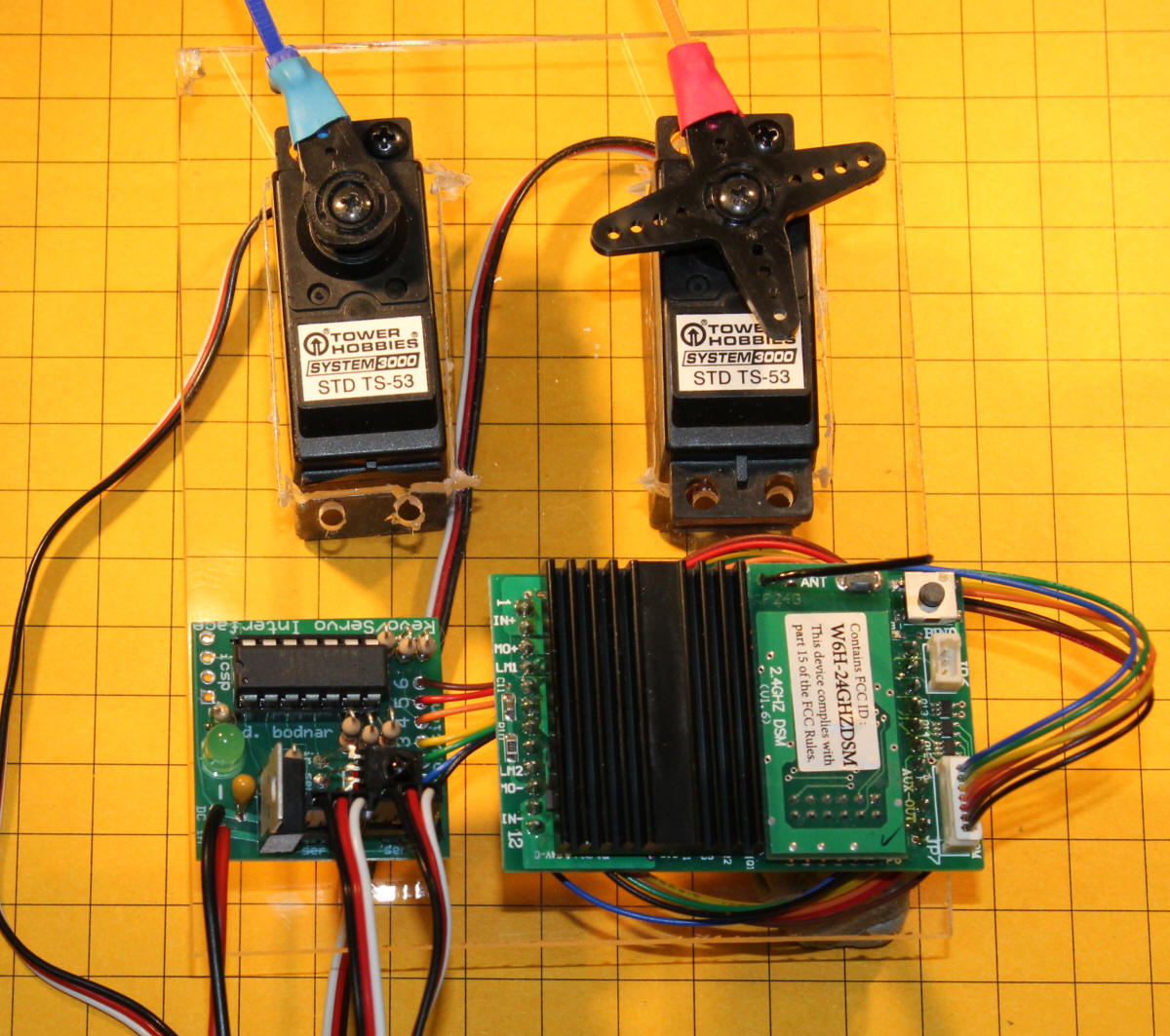
board. This allows a smaller board to be designed. In these photos
the surface mount unit is on the left and the through hole is on the right.
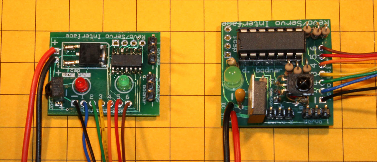
Note that the surface mount version has a number of components soldered to the back of the board.
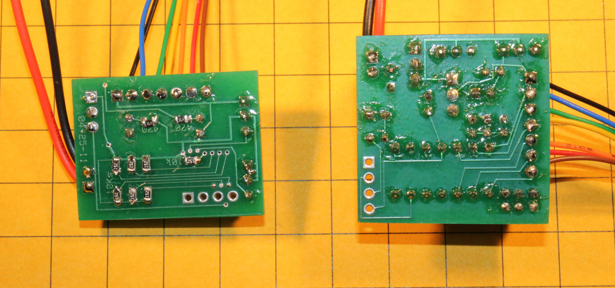
The through hole version measures 1.25" x 1.25" x 0.875" high while the surface mount version is 1.25" x 0.9375" x 0.5".
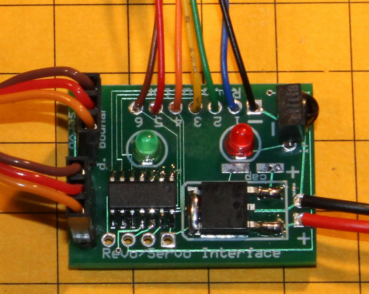
Both of the boards contain a microcontroller, a voltage regulator, an infrared receiver, two LEDs and assorted resistors and capacitors. The key to keeping the component count down is the TV remote control that is used with the infrared receiver on the interface to control all settings, adjustments and configuration.
The small red LED, which is directly behind and under the infrared receiver on the board, flashes whenever the TV remote control us used. It is there to let you know when the interface is "hearing" the TV remote. If you press a button in the TV remote and the red LED does not flash try moving the remote control unit closer to the interface board.
The green LED is used to give you feedback on commands that the interface receives and to let you know when it is ready to receive a command.
Connections
To connect the Servo Interface to the REVOLUTION receiver you need to solder
the seven leads of the auxiliary wiring harness that is included with each
receiver to the unit. The black wire goes to the negative or
common contact. It is labeled "-" as shown in this photo. The
blue wire goes to the contact labeled "1", green to "2", yellow to "3" and so
on.
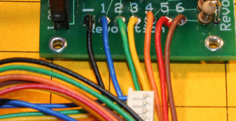
It is not necessary to connect all six of the auxiliary control wires to the interface. If you are only planning on using one servo, as would be the case with the rudder control for the tug boat, you would only need to connect three of the wires plus the common lead. You could get away with only two wires if you only wanted to control left movement and right movement skipping the lead that immediately centers the servo. By using fewer of the control wires you could leave some to operate a sound unit, smoke control board or other accessory.
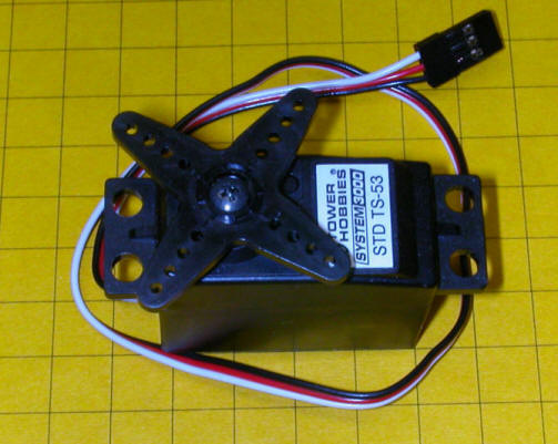
The board, interface cable for the REVOLUTION receiver and two micro servos are shown here. Note that the negative lead on the 3 wire servo cable goes to the left. With these servos that is the brown wire, on other servos the negative lead is black in color. There is a small minus sign next to the negative pin on the circuit board so that you can see where the black (or brown) wire goes.
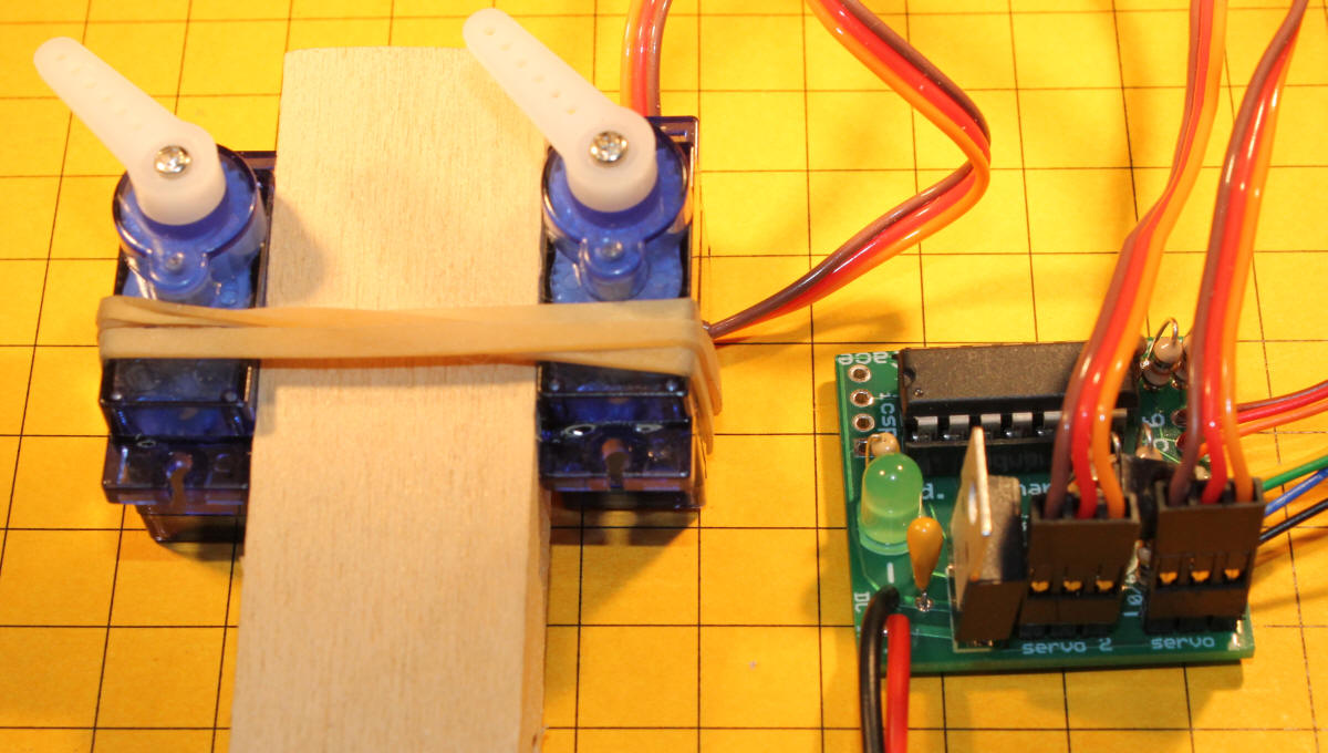
The red and black wires that exit the board in the bottom left go to a source of DC power. This power connection can be to the same battery or other power source that is used by the REVOLUTION receiver. Both the revolution receiver and the servo interface will work with DC voltages between 8 and 24 volts. Lower voltages will allow the system to run cooler. The REVOLUTION receiver is not polarity sensitive but the controller is. Just be sure to observe proper polarity, red to positive (+) and black to negative (-). If you are running from track power where the polarity can change you will need to install a simple bridge rectifier to maintain consistent polarity to the servo board. (Bridge rectifiers are discussed in detail in this article on my web page: http://www.trainelectronics.com/LED_Articles_2007/LED_102/index.htm )
The surface mount version of the circuit is significantly smaller than the standard version and is the best choice if space is at a premium. The servos connect to the left, as shown. The REVOLUTION receiver connects to the contacts at the top and power comes in from the two contacts on the right.
Software
Designing and fabricating the hardware for this interface was by far the
simplest part of the project. Writing, revising and debugging the software
took much, much more time and effort! At this point the code for the
program spans 12 single spaced pages and all but fills the microcontroller's
memory space.
Each time the interface is turned on its green LED flashes out the version number of the software. For example, if the version of the software is 2.5 the LED will flash 2 times, pause briefly and then the LED will flash 5 times.
There are two separate sections of software inside of the controller. The first receives input from the REVOLUTION receiver via the auxiliary wires and moves the servos as they are configured. The second section interacts with the TV remote control and allows the user to change the characteristics and behavior of the servos.
As delivered the servo controller does the following with when buttons on the REVOLUTION transmitter are pressed:
| Button on the REVOLUTION | Default action |
| 1 | Servo 1 moves counterclockwise. A brief button push moves just a little while holding the button moves faster |
| 2 | Servo 1 is moved to its center position |
| 3 | Servo 1 moves clockwise. A brief button push moves just a little while holding the button moves faster |
| 4 | Same as button 1 but for Servo 2 |
| 5 | Same as button 2 but for Servo 2 |
| 6 | Same as button 3 but for Servo 2 |
These behaviors can be changed by using the TV remote control.
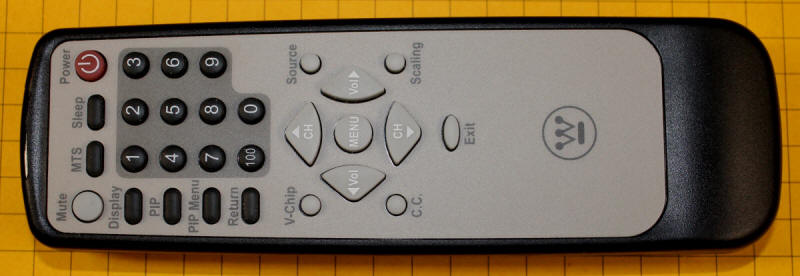
Configuration with the TV Remote
Control
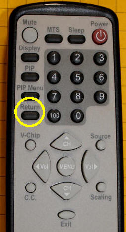
The TV remote is used to modify the controller's behavior. To enter into the
configuration mode put the REVOLUTION transmitter aside and point the TV remote
at the interface and press the "Return" button. The green LED on the
interface will stop flashing and the unit will await additional commands.
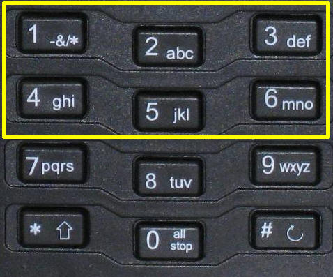
Once you are in the configuration mode the variables in the table can be changed with the keys shown here.
| Button on TV Remote | What the button does | ||||
| 1 | Servo 1, set maximum counterclockwise position - use <Vol and Vol> to move the servo left and right - when it is in the desired position press MENU | ||||
| 2 | Servo 1, set center position - use <Vol and Vol> to move the servo left and right - when it is in the desired position press MENU | ||||
| 3 | Servo 1, set maximum clockwise position - use <Vol and Vol> to move the servo left and right - when it is in the desired position press MENU | ||||
| 4 | Servo 2, set maximum counterclockwise position - use <Vol and Vol> to move the servo left and right - when it is in the desired position press MENU | ||||
| 5 | Servo 2, set center position - use <Vol and Vol> to move the servo left and right - when it is in the desired position press MENU | ||||
| 6 | Servo 2, set maximum clockwise position - use <Vol and Vol> to move the servo left and right - when it is in the desired position press MENU | ||||
| 7 | Alters behavior of Servo 1 - After pressing button 7
you can use these commands
Note: Wait for fast LED blink before hitting key 0-->9 |
||||
| 8 | Alters behavior of Servo 2
Note: Wait for fast LED blink before hitting key 0-->9 |
||||
| 9 | Time before fast move on Servo 1 - enter 0-9
with 0= no fast move, 1=immediate fast move, 9 long delay before fast
move. Note: Press 9 briefly and wait for fast LED blink before hitting 0-->9 - holding 9 for more than 1/2 second will enter 9 as the value |
||||
| 0 | Time before fast move on Servo 2 - enter 0-9
with 0= no fast move, 1=immediate fast move, 9 long delay before fast
move. Note: Press 0 briefly and wait for fast LED blink before hitting 0-->9 - holding 0 for more than 1/2 second will enter 0 as the value |
Press the POWER button on the TV remote control to complete configuration. The green LED will flash out the software version and the unit will return to operating from the REVOLUTION remote control. All settings will be retained after power is turned off.
Advanced Configuration - One Button Operation
The
system can be set to activate a servo from only one button on the
REVOLUTION transmitter so that it rotates from its clockwise (or
counterclockwise) limit to the counterclockwise (or clockwise) limit
pauses for a moment and returns to the clockwise (or counterclockwise)
limit. The limits can be set as shown above and the speed of
motion and pause time between the two movements can be modified as shown
here. This type of behavior would be used, for example, if a servo were
operating an animation like the movement of the spout on a water tank.
Pushing a single button would lower the spout, pause for a few seconds then
return it to its upright position.
| Button on TV Remote | Single button cycles servo from full counter-clockwise limit to full clockwise limit or visa versa |
| 1 | Servo 1 - same as basic configuration to set limit
with <Vol and Vol>-- after
setting limit press a single button (from 1-->9) to activate
1 button sweep - the number used is the pause between clockwise
& counterclockwise in 1/2 second increments Press MENU when done |
| 3 | Servo 1 - same as above but ccw to cw movement |
| 4 | Servo 2 - same as above cw to ccw |
| 6 | Servo 2 - same as above ccw to cw |
| 9 | rate of movement for servo 1 - 1=very slow, 9= very fast Press MENU when done |
| 0 | rate of movement for servo 2 - 1=very slow, 9= very fast Press MENU when done |
Press the POWER button on the TV remote control to complete configuration.
Full
Factory Reset
To return the system to
the settings that were initially programmed into it at production follow
this procedure:
Press the "Return" button on the TV remote and wait for the green LED to stop flashing. Press the "V-Chip" button - the LED will flash rapidly. Press the "Exit" button to fully reset - press the "Power" button to abort reset.
Use with Other Vehicles & Accessories
While the interface was designed with live steam and boat rudder control in
mind there are a host of other uses for servos on our garden railroads.
Because a servo's arm (also called a horn) can rotate 180 degrees with a good
bit of torque they are ideally suited to control animated vignettes.
Water Tank
I have animated the spout on a number of
water tanks. It is a simple matter to hide a servo inside of the tank and
run linkage out to the spout so that it lowers and raises with the movement of
the servo. There is a video of this animation at the link at the end of
this article.
Elephant Trunk
A more difficult animation was done for
Pittsburgh Children's Hospital. It involved mounting a micro servo inside
of a Playmobil elephant. Details on the installation are on my web page
at:
http://www.trainelectronics.com/Animation_servos/Elephant/
Prairie Dogs
A group of prairie dogs were animated to
pop out of and back into their holes for a layout that was build for
Pittsburgh's Phipps Conservatory. Details are here:
http://www.trainelectronics.com/Animation_servos/
Outhouse, Garage & Other Doors
The link above also details how an
outhouse door was animated with a servo. In fact, it is possible to use
servos to animate just about any type of door or gate.
Railroad Crossing Gates
Micro servos are ideal for building animated
crossing gates. They have sufficient torque to lift and lower the arms and
can be made to move very slowly.
A number of commercial units use servos for this purpose.
Switch Points
If you want switch points on your turnouts
that move really, really slowly you can connect them to servos. This is
exactly what I do with the automated switch back line on my HO module.
Details are here:
http://www.trainelectronics.com/Module/index.html
Spotlight Movement
With some reprogramming of the servo
controller it can be modified so that it "pans" a searchlight back & forth
across an area. I recently experimented with such an animation.
http://www.trainelectronics.com/Servo_PIC/SearchLight.htm
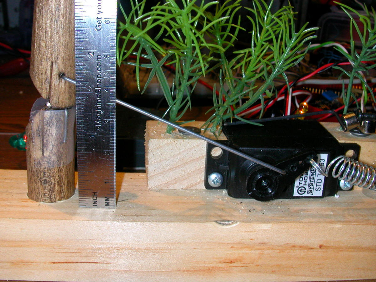
Tree Falling
A very realistic animation of a tree being
chopped down was done for a recent outdoor community layout.

Here is the servo connection to the hinged tree trunk. Note the spring that helps to supply power to put the tree back into a vertical position.
Some photos of the layout and a video of the tree animation are here:
http://www.pittsburghgardentrains.com/Oktoberfest2008/index.html
And Many, Many More!
Servos are so versatile that there is no
end to the things that they and the REVOLUTION can animate. How about
playground equipment, circus swings, a flag going up and down, more animal
movements? How about some animated circus animals inside of moving box
cars? The list is endless.
For more information about the servo interface or if you have ideas for other servo behavior settings or have a need for custom programming of the servo controller please contact me at info@trainelectronics.com.
| Video This video serves as an introduction to the interface and how it operates. If you have questions please contact dave bodnar at info@trainelectronics.com http://www.youtube.com/v/3G_FlOu6GpM?hl=en&fs=1
This video shows two additional features - doing a factory reset and controlling the motion of a servo from only one button
|