Using the 8x32 LED Matrix
To Create
a Mobile, Wirelessly Controlled Display
revised d. bodnar 9-19-2017
Click here to jump to buffer circuit description that may be needed
| Introduction I have used LED matrix displays for a number of different projects over the last few years. These 8x8 LED units have a controller that allows an Arduino to talk to them sending text or graphic information that can be displayed. These small units can be daisy-chained together to create a long, scrolling display. see http://www.trainelectronics.com/Arduino/LED_Matrix/
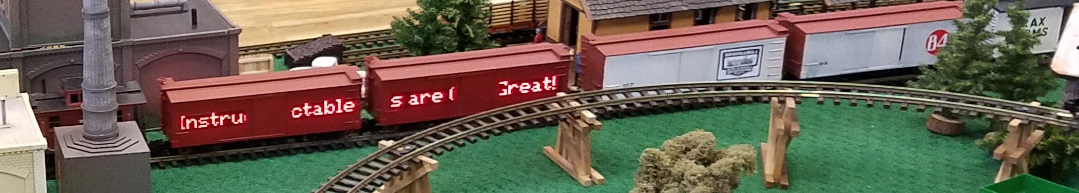
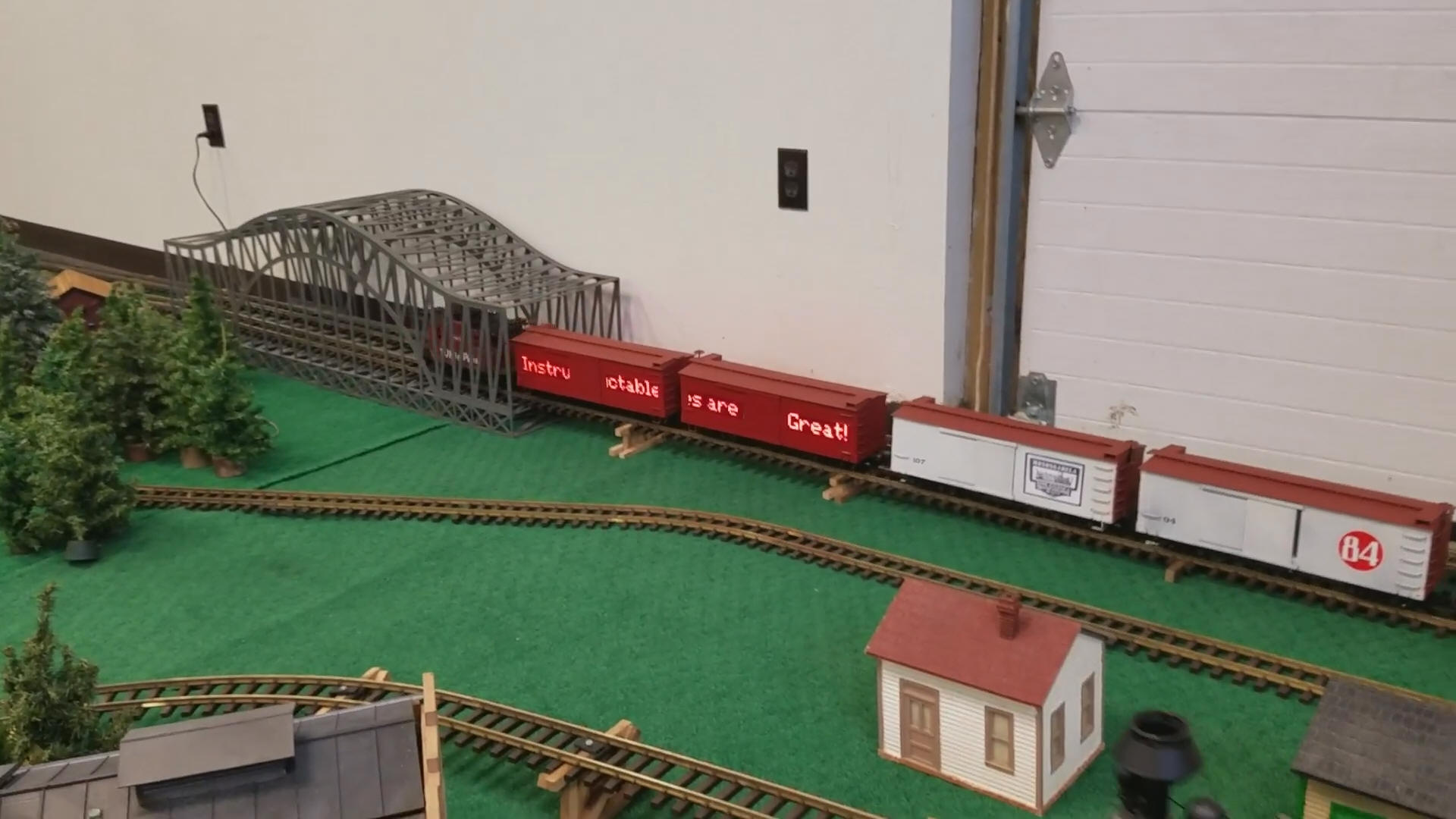
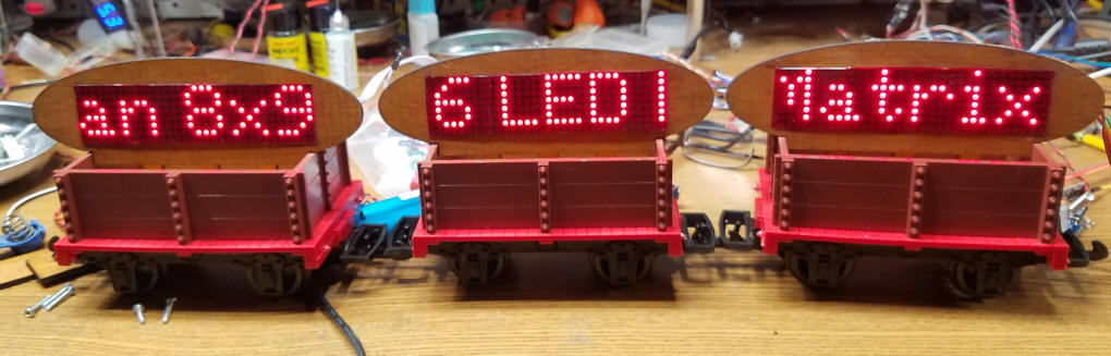
While the displays are visually appealing and easy to use they might not get the amount of attention that one would hope they would generate at a train show or other public train display. With this in mind I decided to build an on-board train display using three 8x32 LED boards. Each board is mounted on a car with the three connected together to crate one long scrolling message board. To make things even more interesting and compelling to visitors the display's message can be changed remotely with a cell phone or computer. My first set of modules were mounted on three small G-scale ore cars.
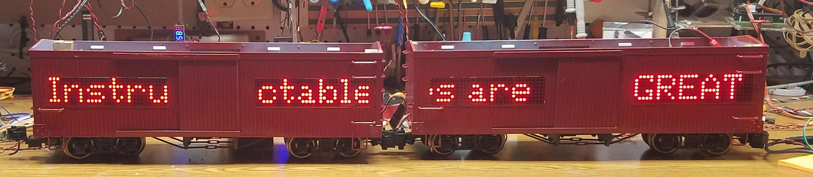
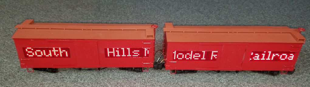
My latest G-scale installation has two modules on each of two box cars. To make it even more interesting the display is duplicated on the back of the box cars to facilitate viewing no matter where the cars are on the layout. A total of eight 8x32 modules are on the two cars.
|
||
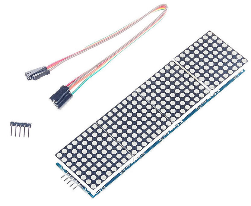
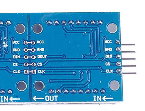
| The Displays The display units are available from Amazon and other vendors. Each is made up of four 8x8 display modules combined on a single circuit board. That makes connections very easy.
The display has a 5 pin input header on its right side and a 5 pin output header on the left. The Arduino is connected to the right side (as viewed from the front) and additional modules are connected to the left. The connections are
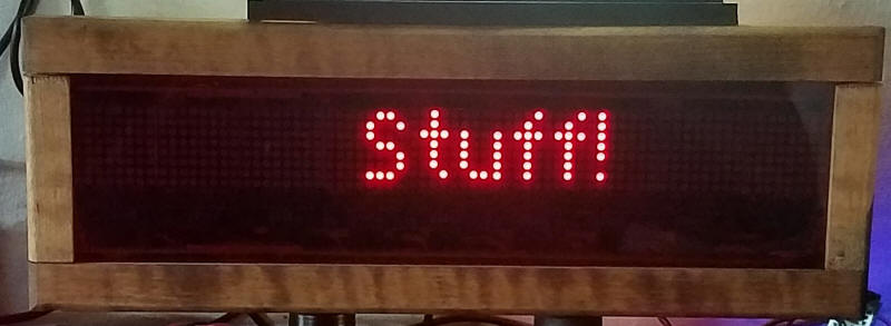
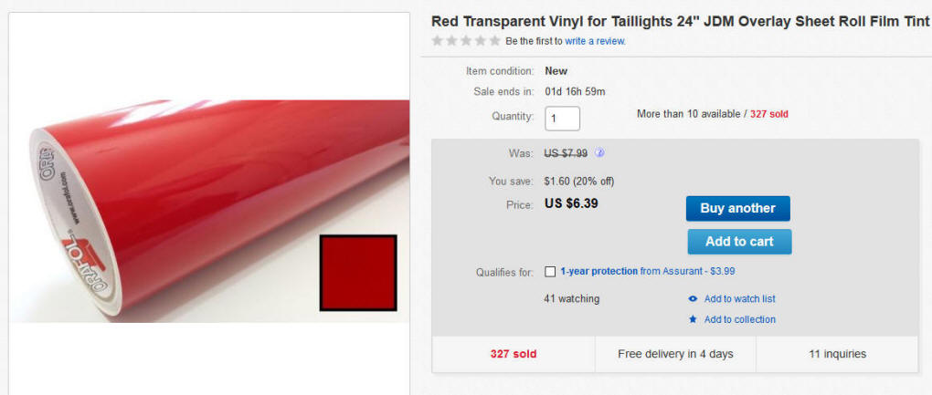
The displays are not as bright as they could be as they are delivered. In order to increase the contrast I always cover such displays with transparent red arcylic or plastic tape. To keep the size and weight down I opted for plastic tape for this installation. I purchased it from eBay.
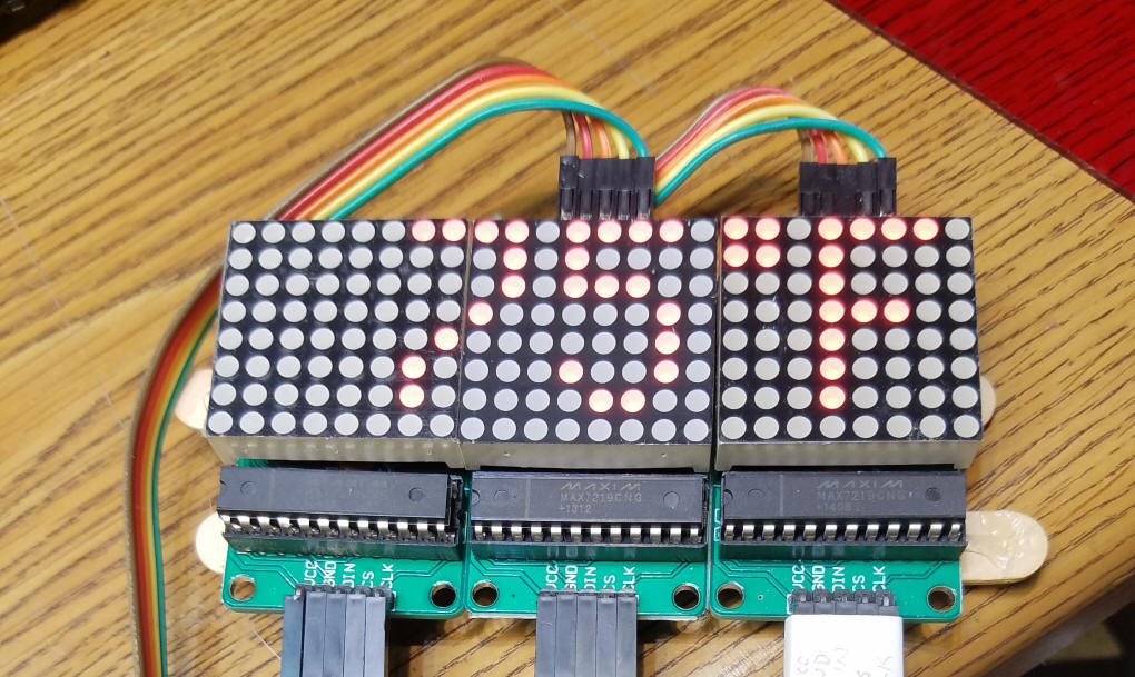
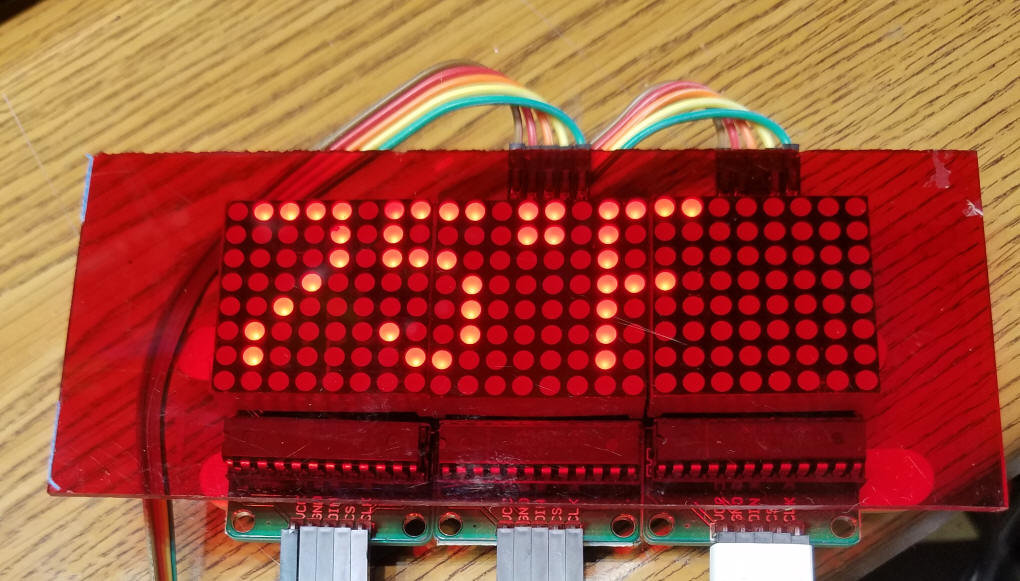
The two photos below show the dramatic difference in contrast when a piece of red tinted acrylic is put over the display.
|
||
| The Circuit Just about any of the Arduino variants should work. I chose to use the Pro Mini and the Nano for my two projects as they are much smaller than the UNO and many of its brothers. This schematic shows the Pro Mini - wiring for the Nano is the same except for the location of some of the pins.
|
||
| The Software Three libraries need to be installed. They are
(note - The KeySwitch library is left over from the Scroll example and is not needed. I left it there as some residual code that I modified does not compile unless it is there. ) The Arduino sketch that I put together is composed of code from a number of sources including an example, Parola Scrolling, from the MD_Parola library. This library allows you to select the orientation of the modules and works very well with the 4 module boards. In order to configure the library for these boards you must edit one line in the https://github.com/MajicDesigns/MD_MAX72XX library. The file that must be edited is called MD_MAX72xx.h On my Windows computer I found this library in the following
directory. When you find the file change the
line that reads Save the file and restart the Arduino IDE.
|
||
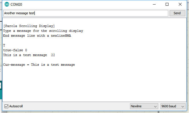
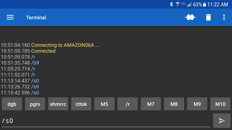
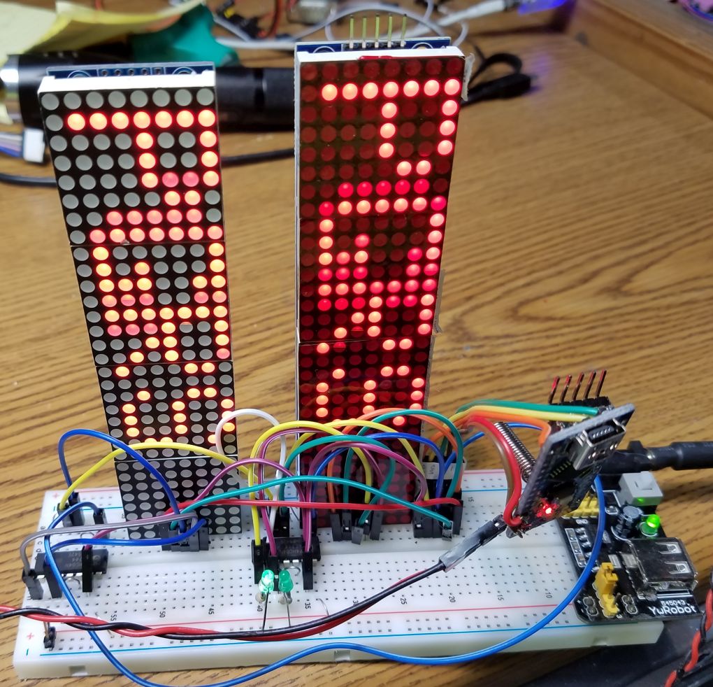
| Command Options The software allows you to enter new messages from the Arduino Terminal as shown here
In addition to entering text you can also enter commands that will change the scroll speed, scroll direction and a few others.
|
||
| A Wireless Connection The message that is shown on the display can be edited from within the sketch or changed from the Arduino terminal if the unit is plugged into a computer. I found this to be tedious as I wanted to be able to have the whole unit moving on a train. To change the message I would have to stop the train, connect the Arduino to the computer and change the message. A remote wireless solution was needed. I considered three different methods of connecting to the moving train wirelessly: WiFi, Bluetooth and a pair of RF Transceivers. WiFi is surely doable but has one big disadvantage that removed it from consideration. In order to use WiFi a wireless network needs to be available. At some public venues (hotels, science centers, etc) WiFi is not open or not available. Rather than setting up my own WiFi router in those situations I opted for two simpler wireless options, Bluetooth and HC-12 transceivers. |
||
| Bluetooth Bluetooth is the easiest and least expensive wireless option. I added a simple Bluetooth board to the Arduino that controls the display with only three connections, vcc, ground and txd to Rx on the Arduino. Note that you need to temporarily disconnect the Bluetooth txd from the Arduino rx to program the Arduino. The Bluetooth module that I used was from Amazon (see: https://www.amazon.com/gp/product/B01FCQZ8VW/ref=oh_aui_search_detailpage?ie=UTF8&psc=1 )
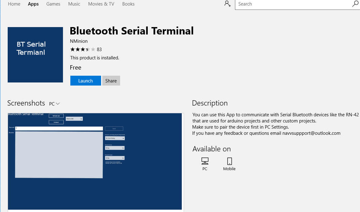
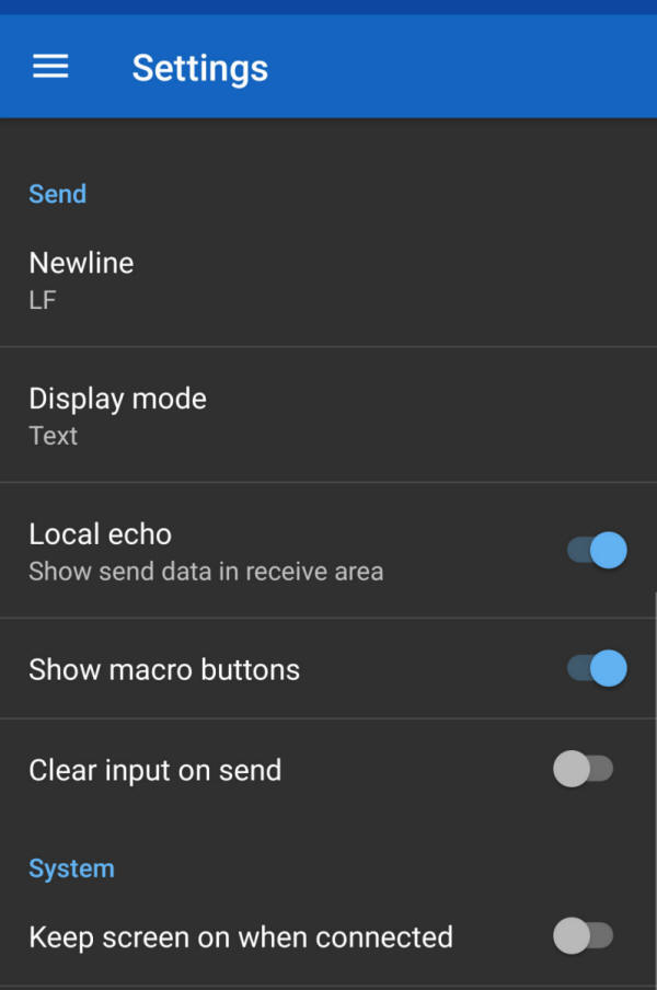
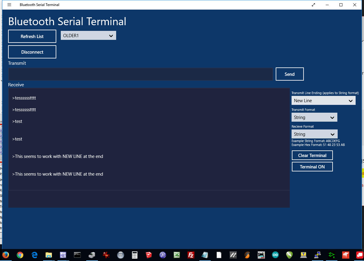
The Bluetooth module can be accessed from a cell phone, tablet or PC that has a Bluetooth capability. On my android cell phone and tablet I used
a free Bluetooth terminal program from Kai Morich - see To start using the app touch the menu bars in the upper left and select Settings. Make sure you change Send Newline to LF as shown here.
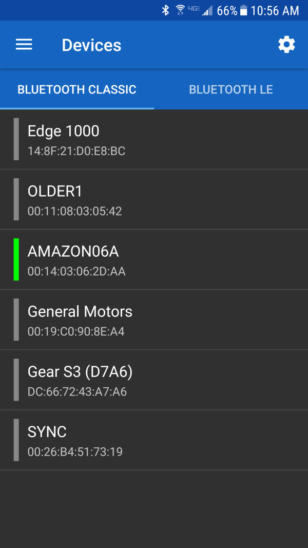
Next go to Bluetooth Devices in the same menu. You should see the devices you have paired. My Bluetooth adapter is named AMAZON06A and is seen here - select your device then go back to the main screen.
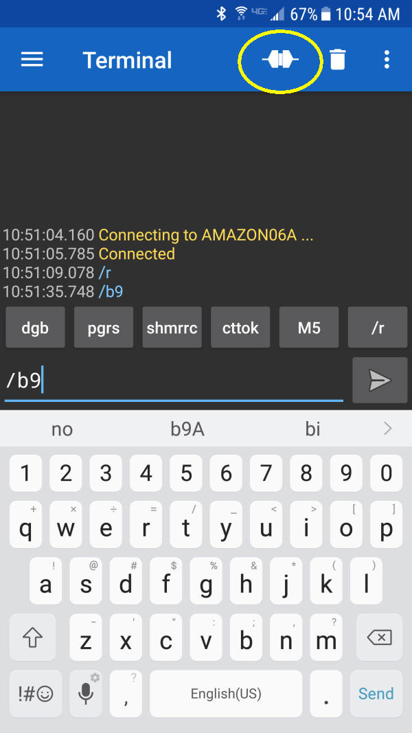
Click the icon that I have circled in yellow and you should connect to your Bluetooth device. Now you can enter new text to be displayed.
You can also enter commands (see the description of these under
Software)
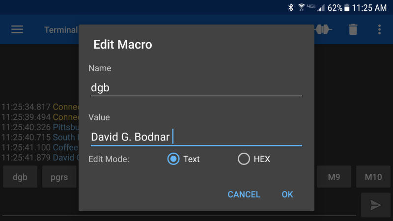
Macros
If you hold down one of the macro buttons you can edit what is says. In this example I replaced M1 with my name.
|
||
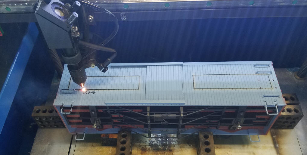
| G-Scale Installation Each of the two G-scale box cars have four holes in their sides to accommodate the 4 LED modules. I cut these holes using my laser cutter but they can also be cut using more traditional methods.
Four holes were cut in each car giving room for a set of 4 modules on each side that display the same message. The wiring is shown. Note that only a single 5 conductor cable is used between cars.
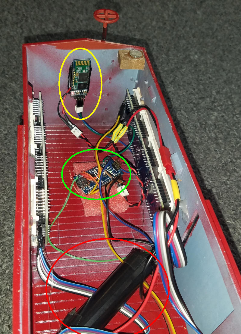
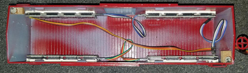
As you can see in these photos the wiring is not complex. The first photo shows the right hand box car that houses the Arduino Nano (circled in yellow on the bottom of the car), the Bluetooth module (circled in yellow and mounted to the back of the car and the battery (circled in red). You can also see the magnet glued to a corner block that holds the roof on - there is another magnet in the opposite corner.
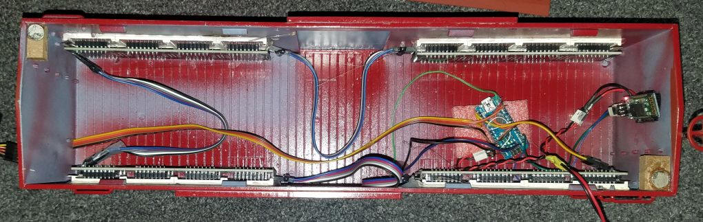
This view shows all four modules. The yellow, orange and black cable that runs the length of the car powers the second box car.
This is the left hand box car.
|
||
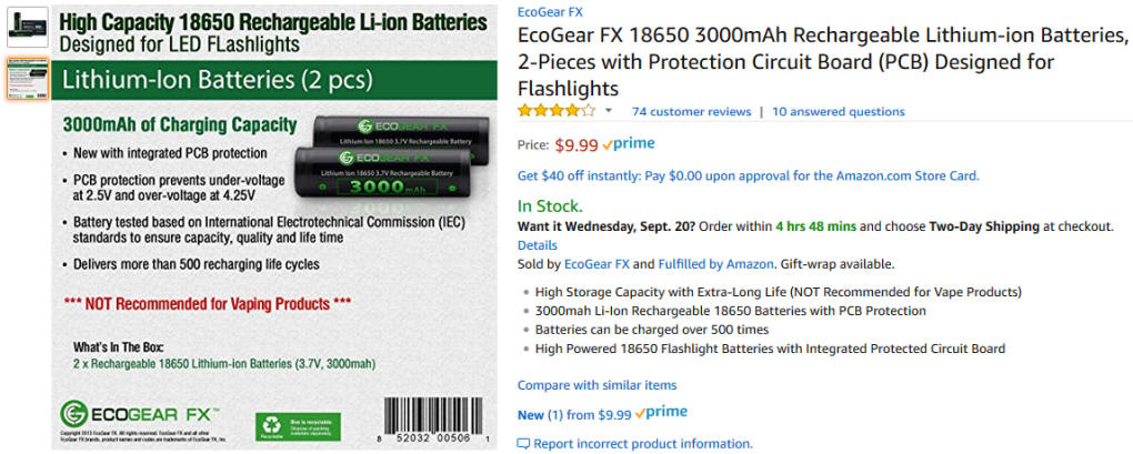
| Powering the Display The boxcar display can be powered in a number of ways. The simplest is to use a 3.7 volt lithium ion cell. I got a 3.5 hour run time from a single 18650 cell that I got from Amazon. This cell has a built in protection circuit that keeps it from being overcharged or over discharged. The cells that I purchased do NOT come with solder tabs so you either need to solder wires to them (not recommended but that is what I did) or put them in a cell holder. You could use 4 NiMH or NiCad cells, providing 4.8 volts or you could use a higher voltage battery and run it through a buck converter to drop it to 5 volts. Getting power from the track is also an option. Since the Arduino and LED modules are sensitive to anything but electrically "clean" power a filter circuit is needed to properly smooth track power. Whatever you use keep in mind that the 8 display units can easily draw more than 1 amp when a long message is being displayed. This can be mitigated to some extent by using the brightness adjustment (see /b# above) and making the display dimmer. You can also put several cells or batteries in parallel to increase the run time. |
||
| Software with /i, /r, /b#, /s#, /x - working Filename: Parola_Scrolling-WORKS-PGRS-v9Breset /////////////REMEMBER to UNPLUG BlueTooth board to program!!!!!!!!!!!!!!!!
// MUST EDIT MD_MAX72xx.h (in users/dave/documents/arduino/libraries/MD_MAX72xx-master)
// from #define USE_FC16_HW 0 to #define USE_FC16_HW 1
// adding /r to scroll in reverse
// adding /i for INVERT
// adding /s# for speed (0-9)
// adding /b# for brightness (0-9)
// adding /d# for delay at end of listing
// adding /x for reset
// Use the Parola library to scroll text on the display
// NOTE: MD_MAX72xx library must be installed and configured for the LED
// matrix type being used. Refer documentation included in the MD_MAX72xx
// library or see this link:
// https://majicdesigns.github.io/MD_MAX72XX/page_hardware.html
//
#include <MD_Parola.h>
#include <MD_MAX72xx.h>
#include <SPI.h>
// set to 1 if we are implementing the user interface pot, switch, etc
#define USE_UI_CONTROL 1
#if USE_UI_CONTROL
#include <MD_KeySwitch.h>
#endif
// Turn on debug statements to the serial output
#define DEBUG 1
#if DEBUG
#define PRINT(s, x) { Serial.print(F(s)); Serial.print(x); }
#define PRINTS(x) Serial.print(F(x))
#define PRINTX(x) Serial.println(x, HEX)
#else
#define PRINT(s, x)
#define PRINTS(x)
#define PRINTX(x)
#endif
// Define the number of devices we have in the chain and the hardware interface
// NOTE: These pin numbers will probably not work with your hardware and may
// need to be adapted
#define MAX_DEVICES 16 // was 12
#define CLK_PIN 13
#define DATA_PIN 11
#define CS_PIN 10
int resetPin = 5; // hard reset pin used with /x command
// HARDWARE SPI
MD_Parola P = MD_Parola(CS_PIN, MAX_DEVICES);
// SOFTWARE SPI
//MD_Parola P = MD_Parola(DATA_PIN, CLK_PIN, CS_PIN, MAX_DEVICES);
int flag = 0;
int InvertFlag = 0;
int ReverseFlag = 0;
int SpeedFlag = 0;
int BrightnessFlag = 0;
int SpeedValue = 1;
int BrightnessValue = 9;
// Scrolling parameters
#if USE_UI_CONTROL
const uint8_t SPEED_IN = SpeedValue;
const uint8_t DIRECTION_SET = 8; // change the effect
const uint8_t INVERT_SET = 9; // change the invert
const uint8_t SPEED_DEADBAND = 5;
#endif // USE_UI_CONTROL
uint8_t scrollSpeed = 15; // default frame delay value was 25
textEffect_t scrollEffect = PA_SCROLL_LEFT;
textPosition_t scrollAlign = PA_LEFT;
uint16_t scrollPause = 200; // in milliseconds
// Global message buffers shared by Serial and Scrolling functions
#define BUF_SIZE 101
char curMessage[BUF_SIZE];
char newMessage[BUF_SIZE];
bool newMessageAvailable = false;
#if USE_UI_CONTROL
MD_KeySwitch uiDirection(DIRECTION_SET);
MD_KeySwitch uiInvert(INVERT_SET);
void setup()
{
digitalWrite(resetPin, HIGH);
delay(200);
// initialize the digital pin as an output.
pinMode(resetPin, OUTPUT);
P.setIntensity(0);
Serial.begin(9600); // was 57600
Serial.print("\n[Parola Scrolling Display]\nType a message for the scrolling display\nEnd message line with a newline");
#if USE_UI_CONTROL
uiDirection.begin();
uiInvert.begin();
pinMode(SPEED_IN, INPUT);
doUI();
#endif // USE_UI_CONTROL
P.begin();
P.displayClear();
P.displaySuspend(false);
P.displayText(curMessage, scrollAlign, scrollSpeed, scrollPause, scrollEffect, scrollEffect);
strcpy(curMessage, " Instructibles are GREAT ");// - South Hills Model Railroad Club - Modular Train Layout ");
newMessage[0] = '\0';
}
void loop()
{
#if USE_UI_CONTROL
doUI();
#endif // USE_UI_CONTROL
readSerial();
if (P.displayAnimate())
{
if (newMessageAvailable)
{
Serial.println("NMA");
Serial.println(" ");
Serial.println(newMessage[0]);
Serial.print("true-false ");
Serial.println(newMessage == "\n");
Serial.print(newMessage);
Serial.print(" ");
Serial.println(strlen(newMessage));
if (newMessage[0] == '/' && newMessage[1] == 'd') { // Delay at end of display \n is line feed
scrollPause = newMessage[2] - 48;
scrollPause = scrollPause * 500; // in half second steps 0 to 9
Serial.print("GOT /d Delay & ");
Serial.println(scrollPause);
// InvertFlag = 1;
flag = 1;
newMessageAvailable = false;
}
if (newMessage[0] == '/' && newMessage[1] == 'b') { // \n is line feed
BrightnessValue = newMessage[2] - 48;
Serial.print("GOT /b BRIGHTNESS & ");
Serial.println(BrightnessValue);
// InvertFlag = 1;
flag = 1;
newMessageAvailable = false;
}
if (newMessage[0] == '/' && newMessage[1] == 's') { // \n is line feed
SpeedValue = newMessage[2] - 48;
Serial.print("GOT /s SPEED & ");
Serial.println(SpeedValue);
// InvertFlag = 1;
flag = 1;
newMessageAvailable = false;
}
if (newMessage[0] == '/' && newMessage[1] == 'x') { // \n is line feed
Serial.println("GOT /x REBOOT");
// InvertFlag = 1;
// flag = 1;
newMessageAvailable = false;
Serial.println("resetting");
delay(10);
digitalWrite(resetPin, LOW);
delay(1000);
Serial.println("RESET");
}
if (newMessage[0] == '/' && newMessage[1] == 'i') { // \n is line feed
Serial.println("GOT /i INVERT");
InvertFlag = 1;
flag = 1;
newMessageAvailable = false;
}
if (newMessage[0] == '/' && newMessage[1] == 'r') { // \n is line feed
Serial.println("GOT /r REVERSE");
ReverseFlag = 1;
flag = 1;
newMessageAvailable = false;
}
if (flag == 0) {
strcpy(curMessage, newMessage);
Serial.println("");
Serial.print("Cur-message = ");
Serial.println(curMessage);
newMessageAvailable = false;
InvertFlag = 0;
}
}
///// HAD TO ADD THE FOLLOWING HERE TO GET IT TO ACC ON NEW scrollPause NUMBER /////
P.displayText(curMessage, scrollAlign, scrollSpeed, scrollPause, scrollEffect, scrollEffect);
P.displayReset();
}
}
void doUI(void)
{
// set the speed if it has changed
{
int16_t speed = map(analogRead(SPEED_IN), 0, 1023, 10, 150);
if ((speed >= ((int16_t)P.getSpeed() + SPEED_DEADBAND)) ||
(speed <= ((int16_t)P.getSpeed() - SPEED_DEADBAND)))
{
speed = SpeedValue * 25;
// Serial.print ("Speed = ");
//Serial.println(speed);
P.setSpeed(speed);
P.setIntensity(BrightnessValue); /// Brightness setting
//scrollSpeed = speed;
// scrollSpeed = SpeedValue * 25; ///////////////////////////////////////////
// PRINT("\nChanged speed to ", P.getSpeed());
flag = 0;
}
}
if (ReverseFlag == 1) // SCROLL DIRECTION
{
PRINTS("\nChanging scroll direction");
scrollEffect = (scrollEffect == PA_SCROLL_LEFT ? PA_SCROLL_RIGHT : PA_SCROLL_LEFT);
P.setTextEffect(scrollEffect, scrollEffect);
P.displayClear();
P.displayReset();
ReverseFlag = 0;
flag = 0;
}
// if (uiInvert.read() == MD_KeySwitch::KS_PRESS) // INVERT MODE
if (InvertFlag == 1) // INVERT MODE
{
PRINTS("\nChanging invert mode");
P.setInvert(!P.getInvert());
InvertFlag = 0;
flag = 0;
}
}
#endif // USE_UI_CONTROL
void readSerial(void)
{
static char *cp = newMessage;
while (Serial.available())
{
*cp = (char)Serial.read();
if ((*cp == '\n') || (cp - newMessage >= BUF_SIZE - 2)) // end of message character or full buffer
{
*cp = '\0'; // end the string
// restart the index for next filling spree and flag we have a message waiting
cp = newMessage;
newMessageAvailable = true;
}
else // move char pointer to next position
cp++;
}
}
|
||
|
|
||
|
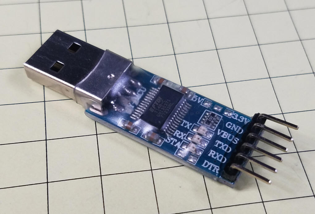
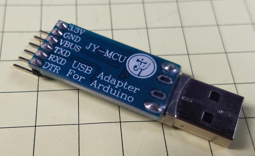
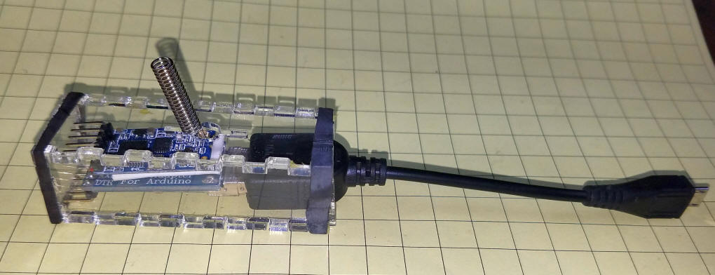
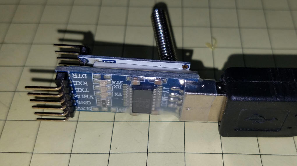
Long Range Option The Bluetooth unit shown above works very well and has been tested to well over 50 feet in a completely open area. If this is not sufficient for your layout there is a longer range method of connecting a phone and the LED modules / Arduino using an HC-12 module. I have discussed this module in some detail on my web page here: http://trainelectronics.com/Arduino/HC-12-Serial_Radio/ In addition to the serial module that I used to setup the HC-12 in the other article you can also use this serial to USB adapter. http://www.dx.com/p/jy-mcu-usb-serial-port-adapter-download-line-arduino-104322
Note that the transmitter unit that connects to the phone uses the power from the cell phone to power both the USB to serial adapter and the HC-12. If you prefer you can remove the VCC to VCC connection and apply 5 volts to the VCC connection on the HC-12.
In order to send a new text string to the display a serial terminal program needs to be installed on the cell phone. On my Android phone I used a free app called Serial USB Terminal - works well and includes some macros to record some common announcements - nice! |
||
|
||
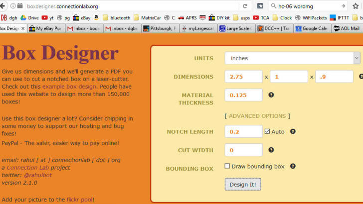
| To protect the transmitter module I
designed a small plastic box using "Box
Designer". This was imported into
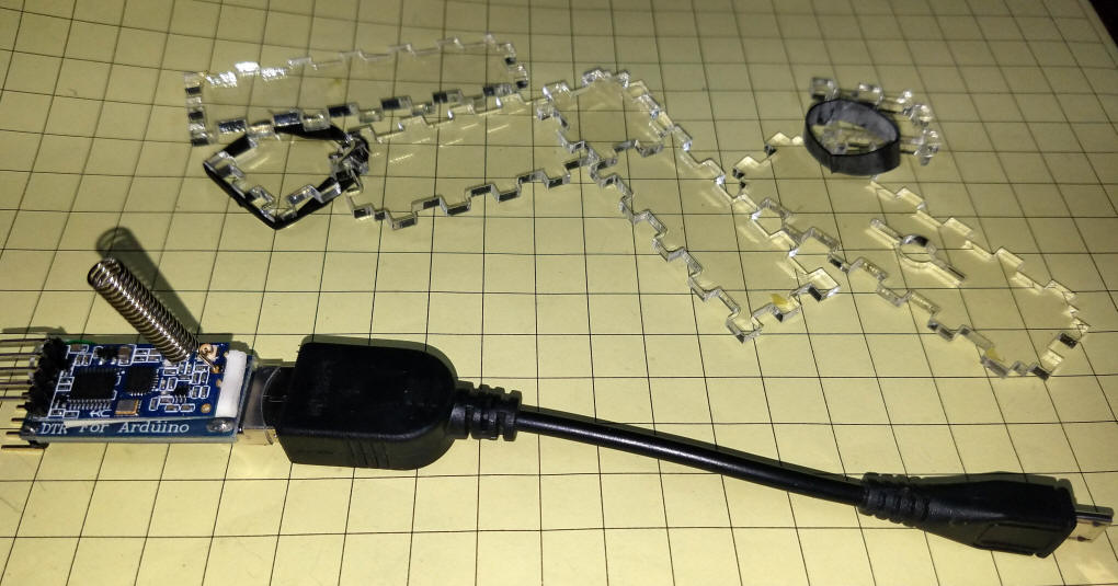
CorelDraw, modified a bit and cut out with my laser cutter.
Here the transmitter and case parts are shown...
... and here the module is in the case.
|
||
|
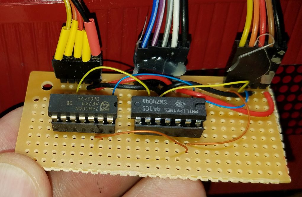
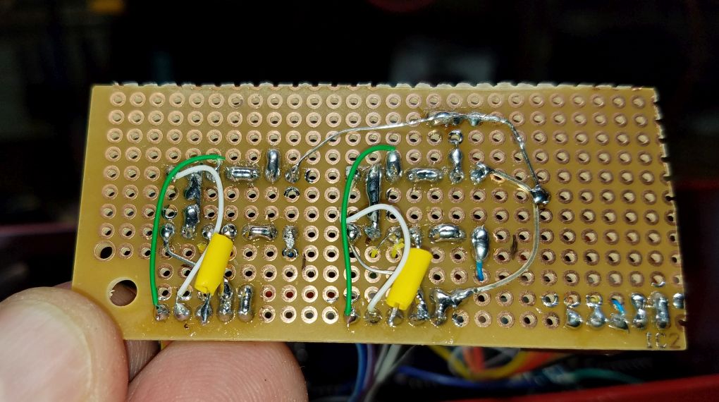
Buffer for two Display
Segments I discovered some issues with the dual displays on the G-scale box cars. Since the two display sets are wired in parallel I theorized that insufficient signal may have been being supplied to each display. A buffer circuit was designed and added to the two displays. The circuit, utilizing just two 7404 ICs, is shown here.
Click here for larger schematic image.
|
