| Hardware:
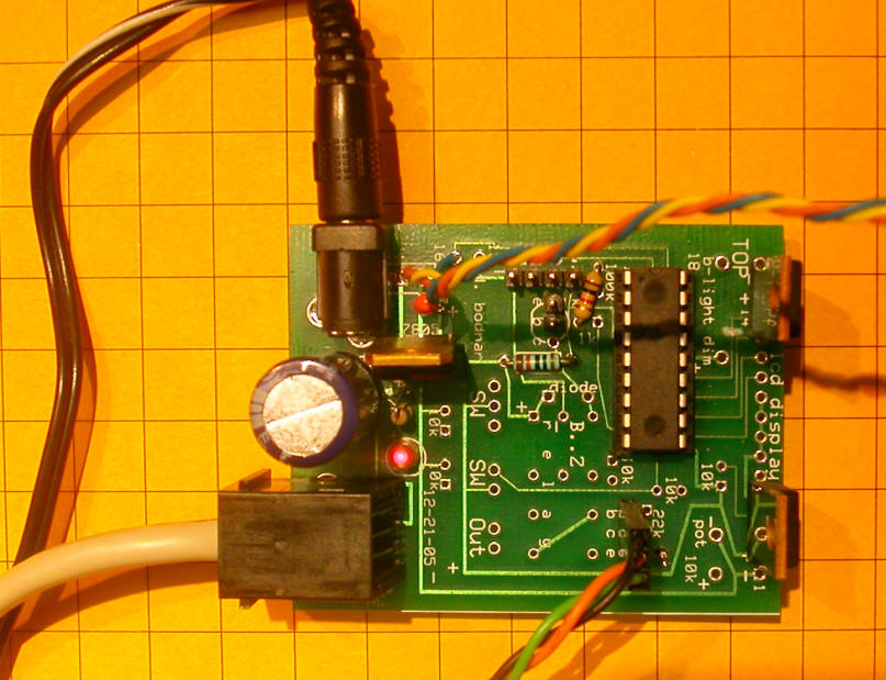
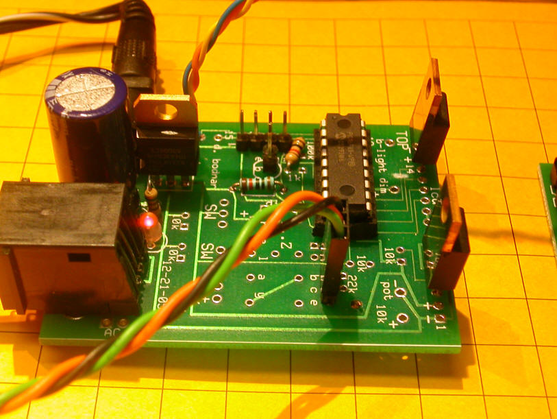
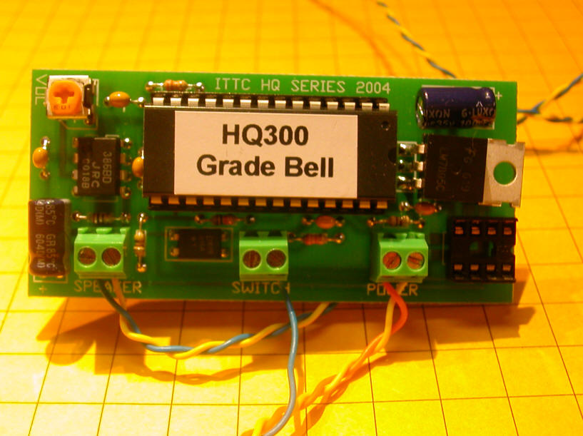
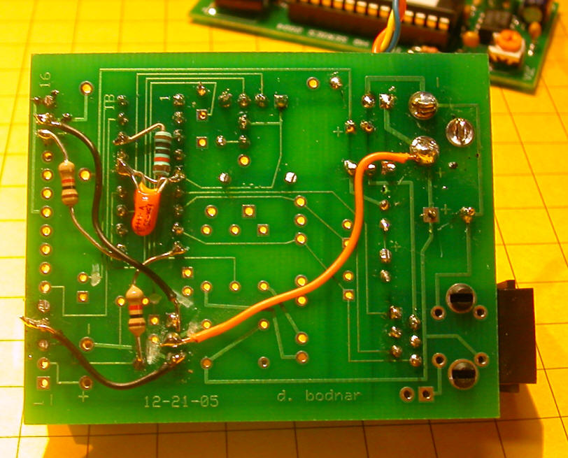
A 16F88 PIC processor runs the system. It is installed on a modified board from the Multi Scale Train Speedometer. Two power transistors were added to power the incandescent bulbs. The same type of IR sensors are used as with the MSTS. The sound card is from ITT Sound The crossing lights are from Model Power . Please note that the original lamps were replaced with Lionel 12 volt, red incandescent bulbs. |
| Schematic: Click on this thumbnail to see the schematic
Note that the schematic has been revised to include the relay that silences the speaker unless the signal lights are active.
|
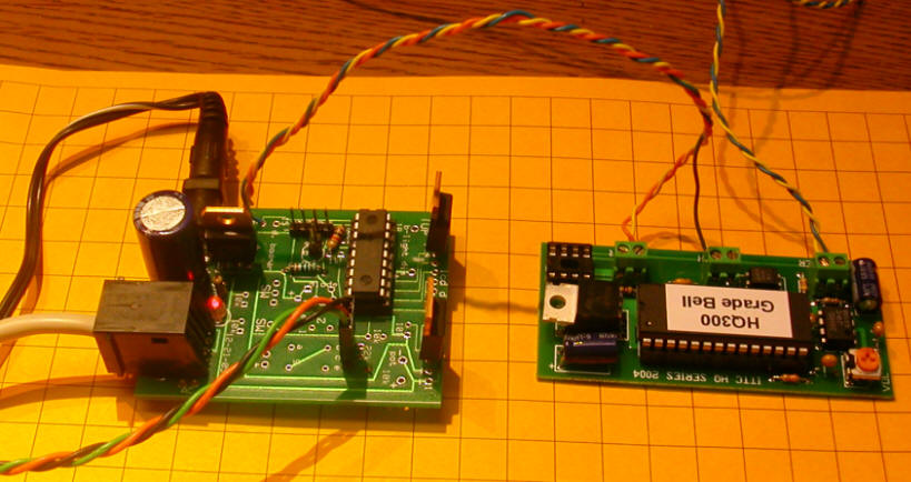
| Completed unit: |
|
The grey cable in the lower left goes to the sensors. It has a modular (telephone) cable connector and plugs directly into the matching receptacle on the board.
The three wire (orange/green/black) cable at the bottom goes to the lights and plugs into the three pin header next to the main PIC chip. It can go in either way.
The three wires (yellow/blue/orange) go from the main board to the sound board. The orange and yellow wires go to power and the blue wire goes into the switch connections on the right of the two pin connector. The volume control is in the upper left corner of the board. Adjust it with a small screwdriver.
The two wires (yellow and blue) go from the sound card to the speaker. |
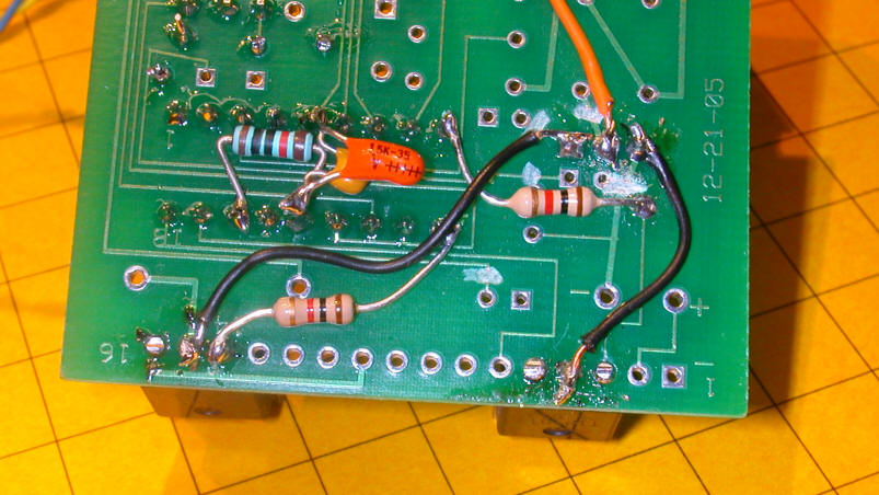
| Board Back:
|
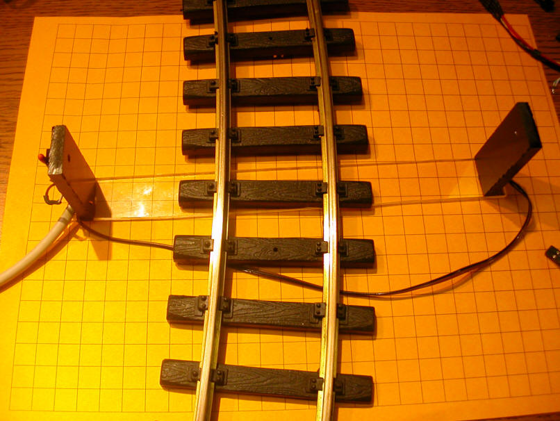
| Sensors The two sensor units go under the track. The emitter is on the right and the detector is on the left. The unit needs to be kept out of direct sunlight. The detector will be blinded if sunlight falls onto it. The easiest way to accomplish this is to put a small building or pile of wood or some other structure over it. Just make sure there is a hole in the side so that the IR from the emitter can get to it! Another option is to have the sensor next to a structure that keeps the sensor in shadow.
|
|
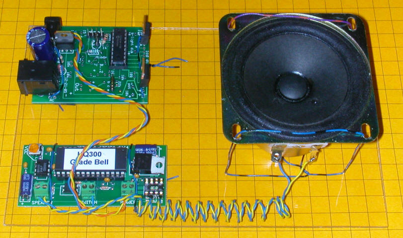
| As Shipped: The circuit board, sound board and speaker are mounted on a piece of Plexiglass.
|
| Software - revision 16F88-Crossing_controller_2-0 |
| 'Crossing / sensor system for John D -
1-23-07 'revised 3-26-07 - relay added to stop sound when flashing stops 'relay on pin 11 'Works well! 'NOTE: Big problem with resets until large CAP installed on power supply! Include "modedefs.bas" OSCCON = %01100111 'MUST BE USED to set clock speed =$67 cmcon=7 'allows you to use pins as digital rather than analog ansel=0 'allows you to use pins as digital rather than analog @ DEVICE PIC16F88, INTRC_OSC_NOCLKOUT, WDT_OFF, LVP_OFF, PWRT_ON, PROTECT_ON, BOD_ON DEFINE OSC 8 OSCCON = $70 Serial_out var PORTA.2 'pin 1 on chip sw1 var portb.1 'pin 2 on chip sw2 var portb.2 'pin 3 on chip switchflag var byte 'keeps track of which sensor was hit flashcount var word 'used to keep flashing while end check is done irLED con 2 'gives 38 KHz on pin #5 on chip temp var word 'pgmdelay con 100 serialin var portb.0 sounder var porta.7 'pull low to activate sound board relay var portb.5 'pin 11 - used to start/stop sound completely lamp1 var portb.3 'one crossing bulb lamp2 var portb.4 'the other crossing bulb TRISB = 0: trisb.1=1 trisb.2=1 'make sw1 & sw2 inputs trisa.3=1 'make pgmswitch an input trisa.2=0 'serial output trisb.5=0 trisa.6=0 trisa.2=0 trisa.7=0 trisb.3=0 trisb.4=0 temp=0 hpwm irLED, 127,38000 serout serial_out,n9600,[10,13,10,13,"Very Top v2.0",10,13,10,13,10,13] pause 500 high sounder:low relay low lamp1:low lamp2 'test: 'high relay: pause 1000:low relay:pause 1000 'goto test: top: switchflag=0 rem sw1 & sw2 = 0 when "seeing" 38 KHz IR, =1 when blocked serout serial_out,n9600,["Sw1 Sw2 f1 f2 ", #sw1, " ",#sw2," TOP",10,13] if sw1=1 then switchflag=1 high lamp1:low lamp2 goto blink endif if sw2=1 then switchflag=2 high lamp1:low lamp2 goto blink endif goto top: blink: serout serial_out,n9600,["FLASHING Swflag= ",#switchflag,10,13] high relay 'activate sound low sounder 'start sound card for temp=1 to 20 'check for other sensor being hit if switchflag=1 and sw2=1 then flashcount=temp 'pass along flash number to keep it even goto doneflashing endif if switchflag=2 and sw1=1 then flashcount=temp goto doneflashing endif pause 25 'this pause with the for/next gives 1/2 second flashes next temp toggle lamp1:toggle lamp2 goto blink: doneflashing: serout serial_out,n9600,["Ready to STOP! ! ",10,13] for temp=1 to 100 'check for break between cars - don't stop till all have passed flashcount=flashcount+1 'timing for flashing while looking for car breaks if flashcount >= 25 then toggle lamp1:toggle lamp2 flashcount=0 endif if switchflag=1 and sw2=1 then doneflashing if switchflag=2 and sw1=1 then doneflashing pause 20 next temp low relay: high sounder:low lamp1:low lamp2: 'all off serout serial_out,n9600,["STOPPED! ! ",10,13] pause 3000 goto top |