|
The Multi-Scale Train Speedometer (MSTS) is designed to add to the enjoyment of your model railway by allowing you to accurately measure the scale speed of any train and answer the age-old questions “How fast is it really going?” and “Is it running at a realistic scale speed?”. The MSTS displays speed in actual miles (or kilometers) per hour and can be adjusted to display any scale speed from 1:1 (full size trains) to 1:220 (Z-gauge). In addition it will keep track of (no pun intended) the number of times a train has passed by, displaying the number of laps it has completed. The unit can be easily configured to display speed using either English (scale miles per hour) or Metric (scale kilometers per hour) units. |
|
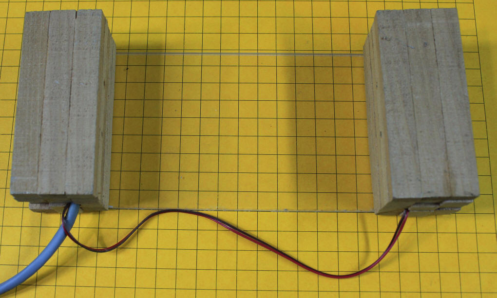
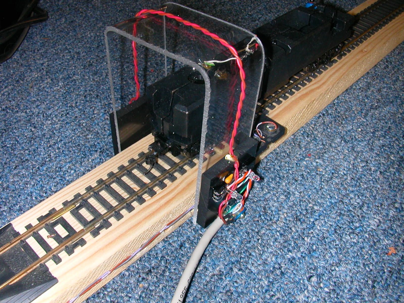
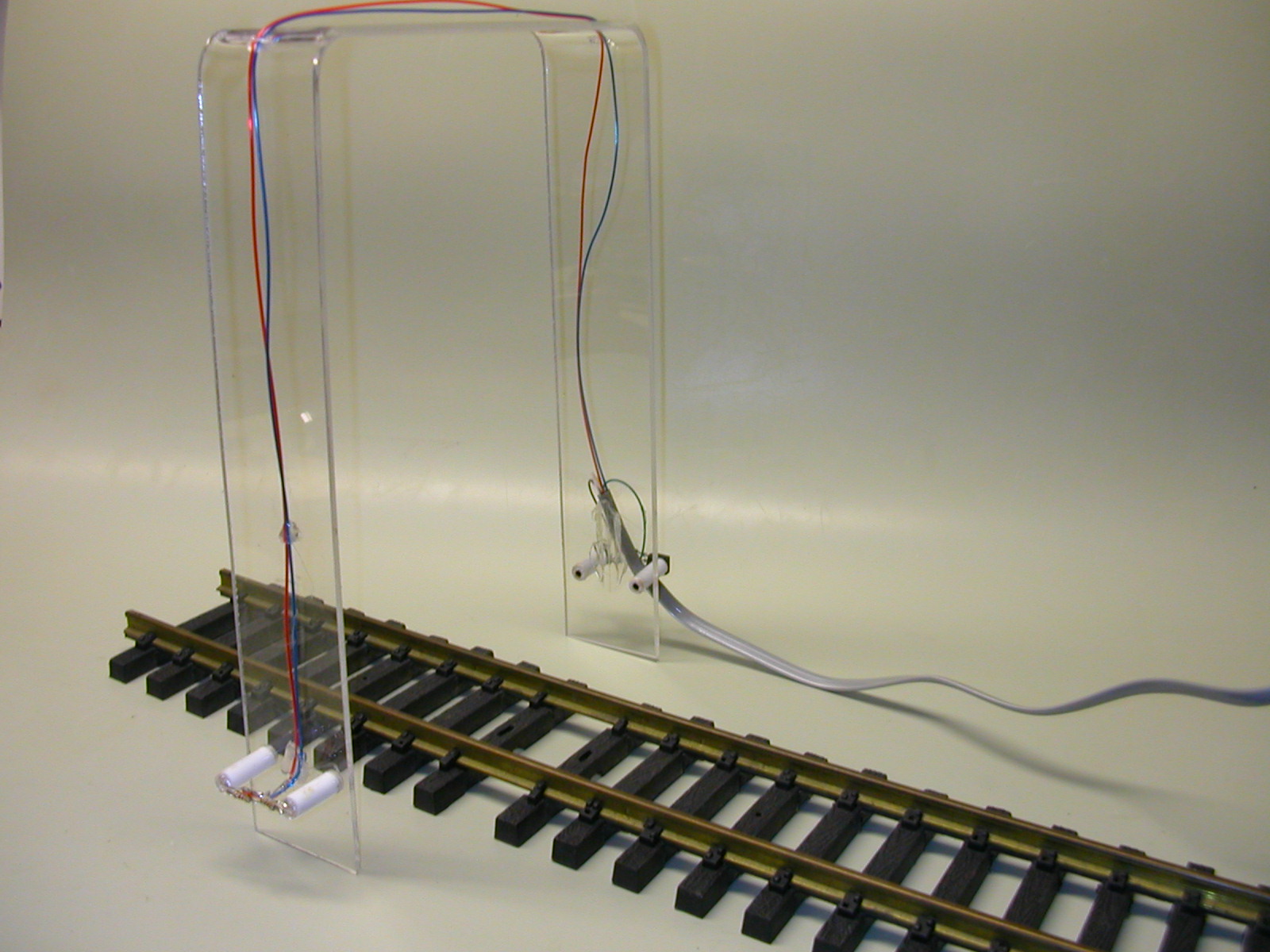
The MSTS computes the speed of a passing train by measuring the time it takes to pass between two infrared photo gates that are spaced exactly one inch apart. In order to work reliably in a garden railway environment, where sunlight plays havoc with IR photo sensors, the infrared emitters are pulsed at 38 KHz and the detectors are designed to respond only to IR light that is pulsed at the same rate. The standard sensors are housed in a transparent U-shaped holder, pictured above, that is normally placed over the track. The sensors can easily be hidden inside of various track side structures for a permanent installation. (See the sensor mounting guide for more options). Note that different sized sensor holders are available for different scales. Custom sensor mounts are also available. Please click on the small images below to see other sensor options.
|
| An alternate, more weather proof mounting for the unit is available at an additional cost. Click here for details. |
|
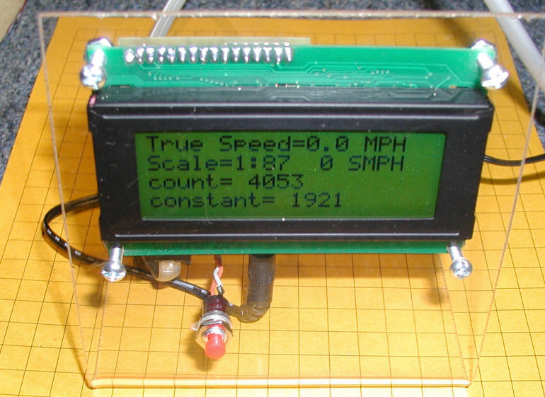
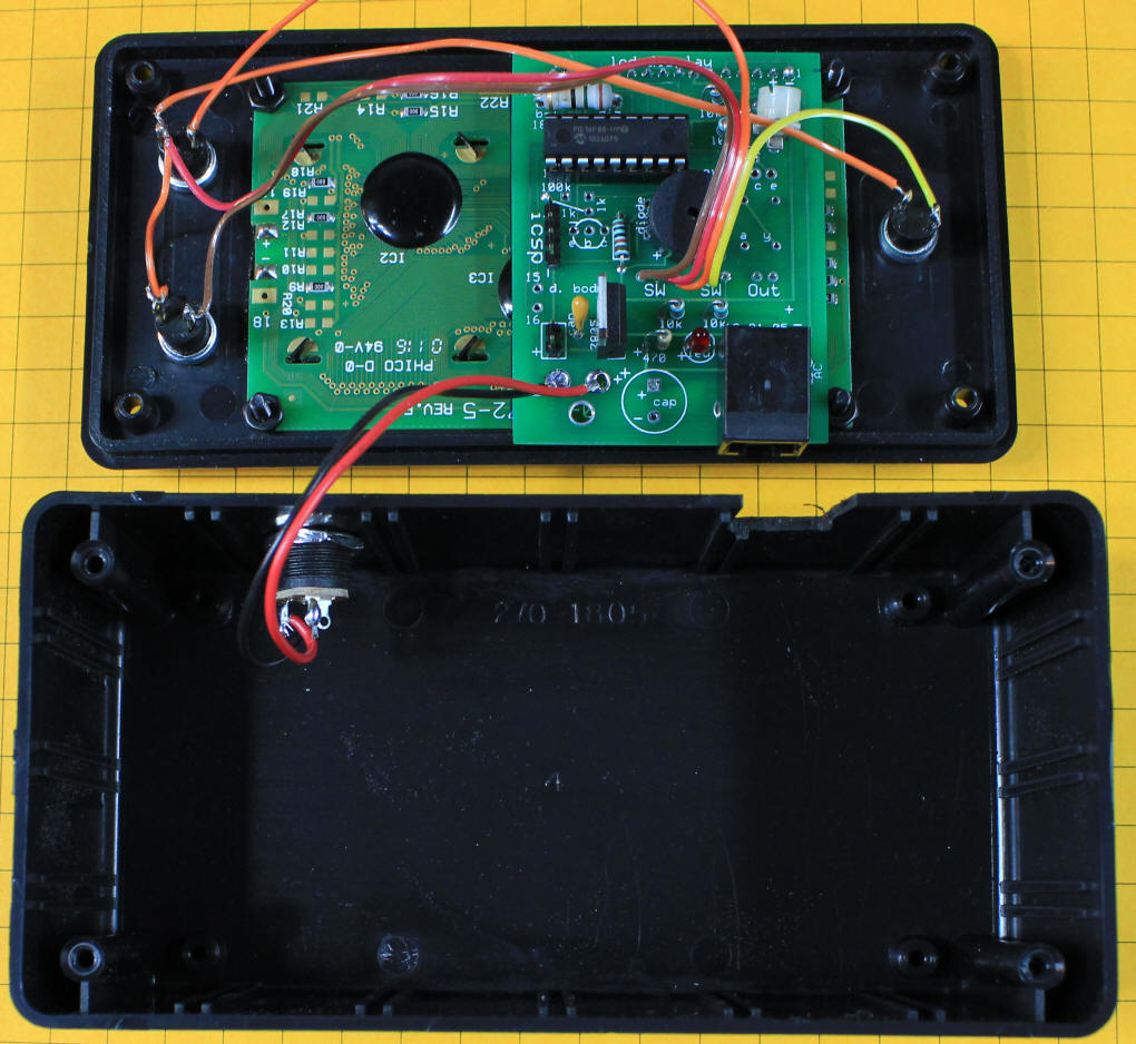
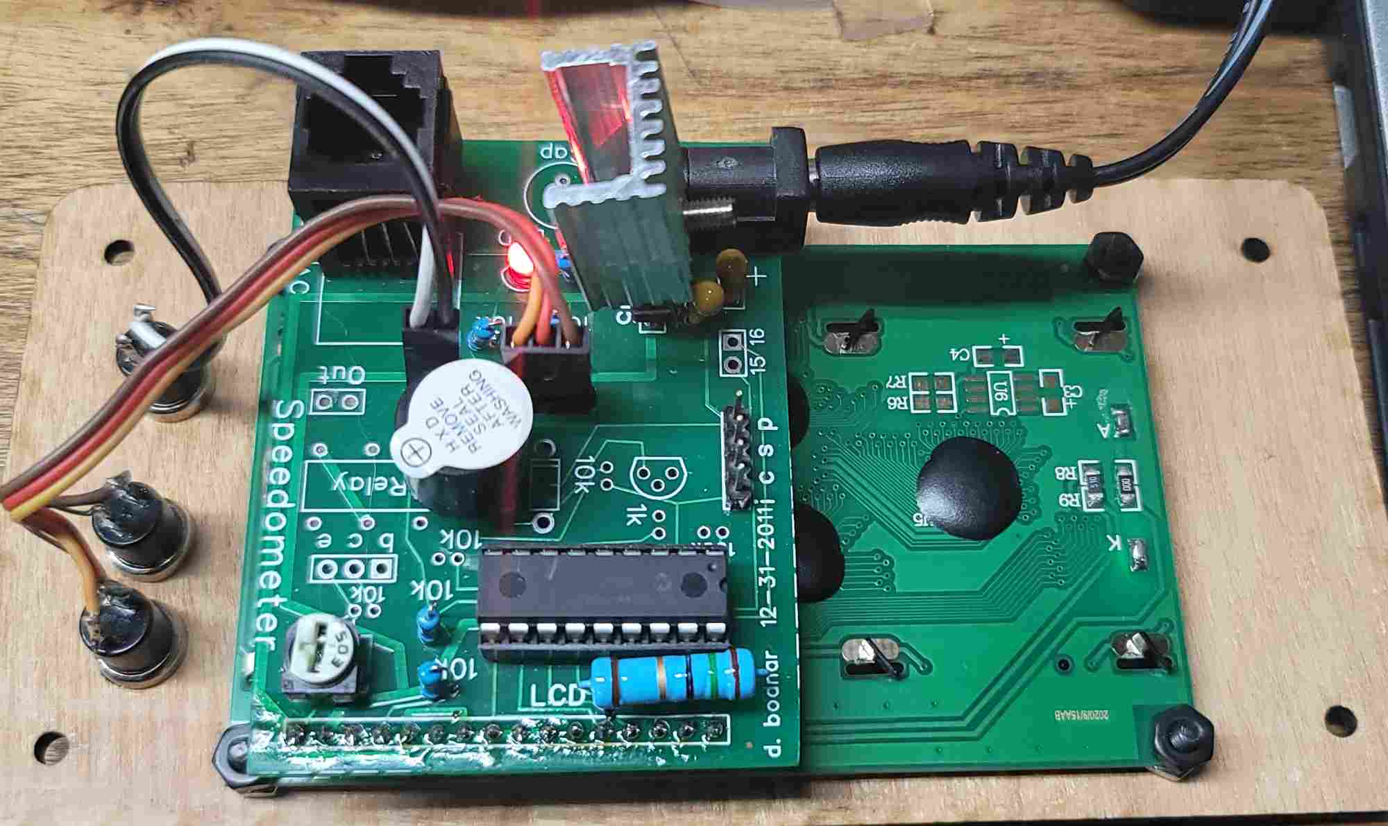
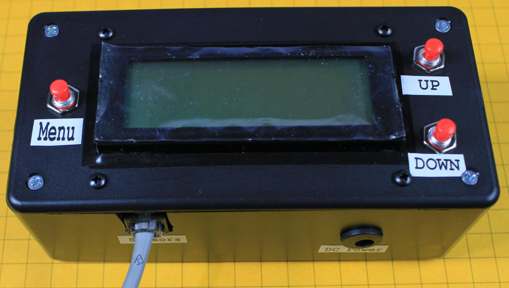
The circuit board and four line by twenty character backlit LCD display comes mounted on an attractive acrylic base. If desired the display can easily be removed from its base and mounted in your own control panel. Power can be supplied by batteries or the DC output from a transformer. Voltages can range from 6 to 9 volts. If a higher voltage power supply is used the voltage regulator is likely to get very hot, not a particularly good thing, so try to keep it at 9 volts or less. |
|
|
|
Initial setup 1. Connect the cable from the IR sensors and IR LEDs, which terminates in an RJ-12 plug, into the matching receptacle on the circuit board. Note that the RJ-12 plug looks like a standard telephone connector.
2. The two IR LEDs must be placed directly across from the two IR sensors. They must be precisely aligned to get accurate results. The most accurate and reproducible results will be achieved if the IR sensors are placed as close as possible to the side of a passing train. Note that the LEDs that are in the image below are no longer used as the software has been modified to send bursts of IR rather than a continuous stream. Due to this modification the lights do not function.
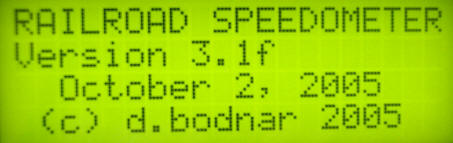
3. Connect the MSTS to an appropriate power source. 4. If the sensors and LEDs are properly aligned when power is applied you should see an initial screen that shows the software version and a copyright notice. 5. If the sensors are not properly aligned or if one or both are blocked the LCD will automatically display an LED alignment screen. Adjust the position of the LEDs and sensors until both sensors display “ON”. Press the “Program” button to exit and return to the setup screen. 6. Test the sensors by blocking just one IR detector. You should see “sw 1 activated” or “sw 2 activated” on the display. Block the 2nd sensor and you should see the speed display screen. 7. Note that the speed display screen will flash "TRAIN" until both sensors are unblocked. This feature keeps a long train from giving multiple readings as the unit senses the space between cars as they pass. When no train has been detected for several seconds “Train passed…READY” will be displayed and the unit will be ready to time the next train. |
|
Setting scale
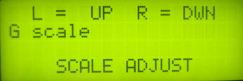
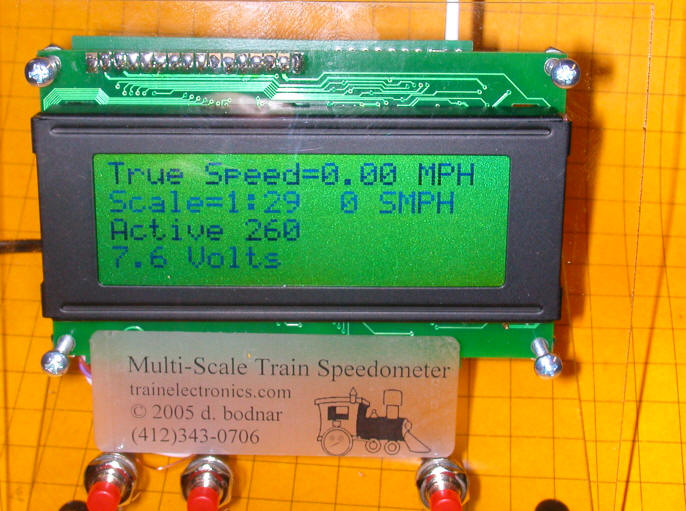
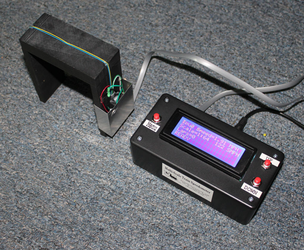
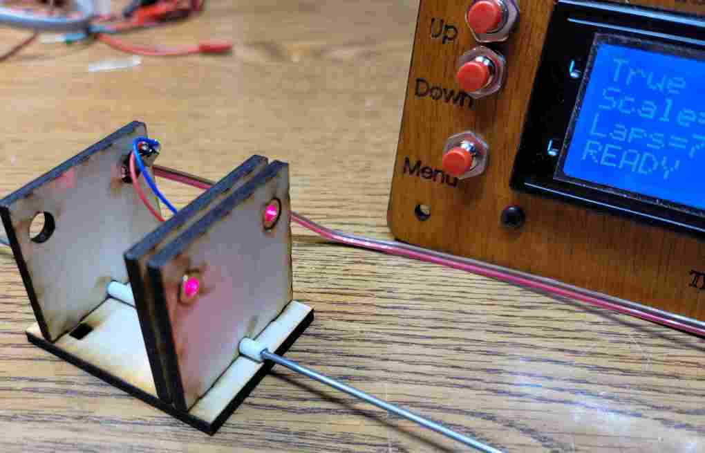
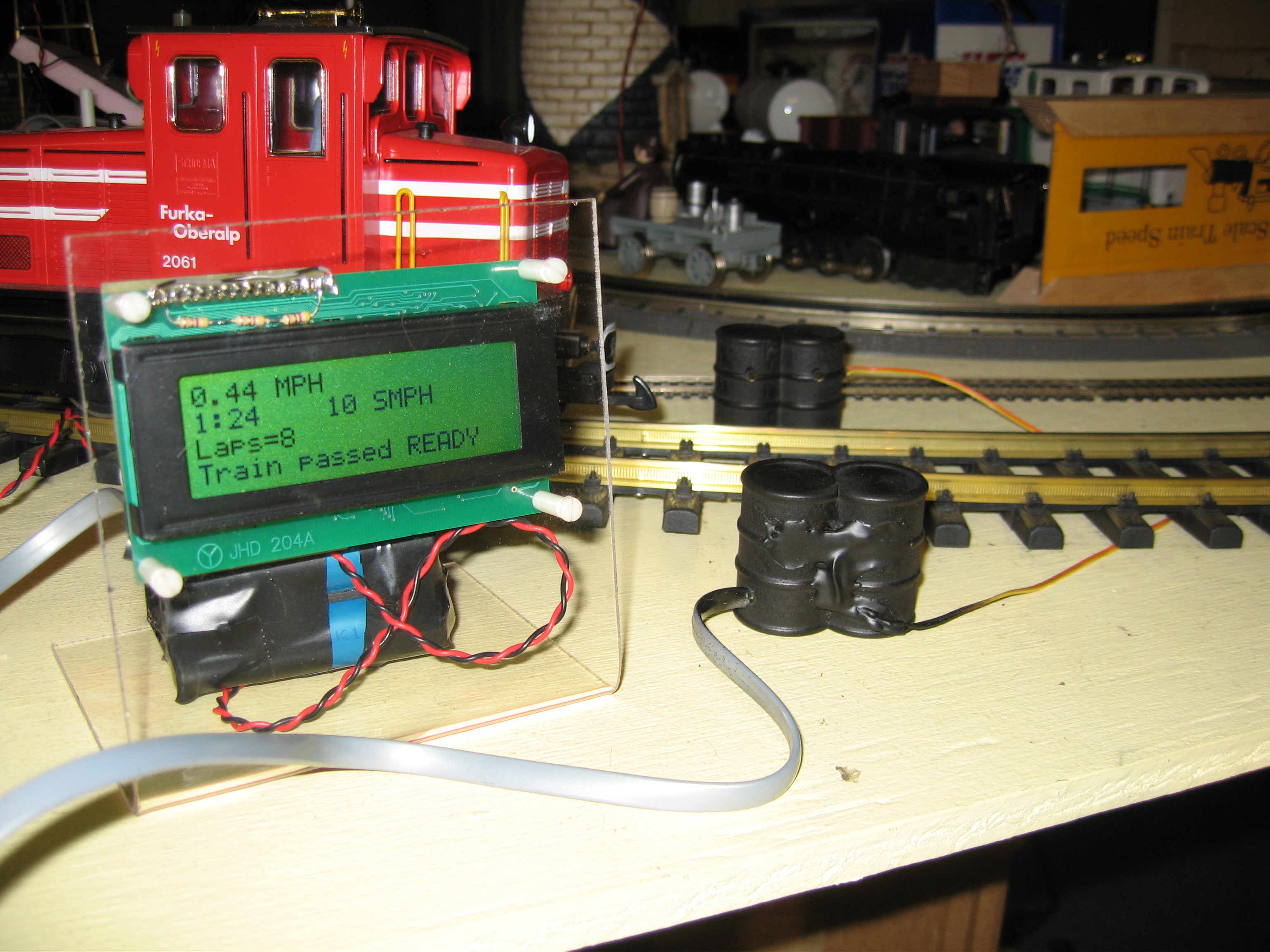
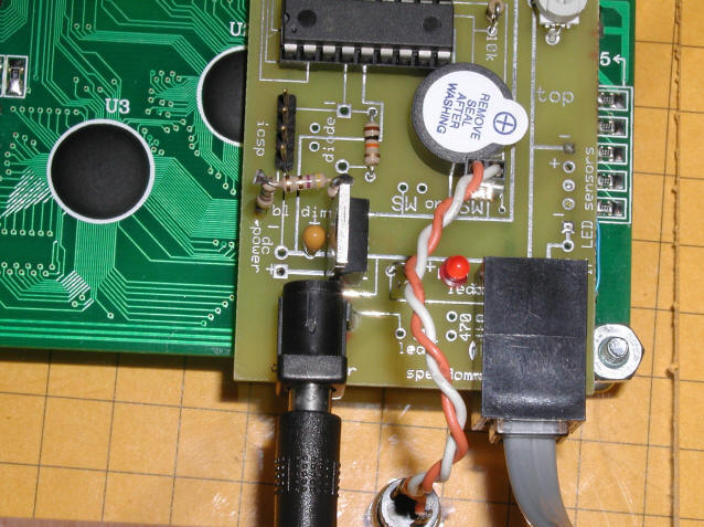
1. The range of scales supported is 1:1 through 1:220 2. To activate the programming mode press and hold the “Program” button while the initial screen is displayed at power up. The program button is the red button below the display in this picture.
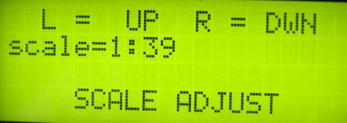
3. The display will show “SCALE ADJUST”, "Block Sensor to Adjust" 4. Briefly block either of the sensors with your hand and you will see the current scale displayed followed by: “L = UP R = DWN” 5. To change the scale block the left or right sensor to move up or down the list of scales. 6 Note that the text representations of scale (as displayed below) are not used in the latest software versions. Scale is shown as a ration only, 1:24, for example.
7. Press the “Program” button when the desired scale is displayed 8. You will be returned to the startup screen and can begin to use the unit. 9. Note that once the scale setting has been changed the speedometer will remember it even after the power is disconnected.
Note: On the wired version of the MSTS you use the two IR sensors to adjust scale and other features. On the wireless version (shown above) there are two additional buttons (the ones together on the left in this photo) that are used to make adjustments. |
|
Setting other options 1. If you follow the first three steps under “Setting Scale” you can move to the other setup options by pressing the “Program” again and again. 2. The next option is "SENSOR ADJUST". This is the same program mode that you will see if you don’t have the LEDs and sensors properly adjusted when the unit is powered on. You may want to enter this mode manually to adjust or test the alignment of your sensors. 3. The next option is "MILES / KILOMETERS". You can change from one to the other by briefly blocking either of the sensors until the new value is displayed. Press the “Program” button to save your setting. 4. Next you will be given the option of turning the sound on or off. Make this change in the same manner that you did Miles / Kilometers, pressing the "Program" button when done. 5. The last setting is “CONSTANT ADJUST”. This option allows you to adjust the master value that is used to control the computation of the train’s speed. This constant should NOT be changed unless you set spacing between the sensors to a distance other than exactly 1”. If, for example, you have your sensors spaced 1.1” apart you could increase the constant by 10% to have an accurate speed displayed. If you do decide to change this value make sure you jot down its setting so that you can return to it should you need to. |
|
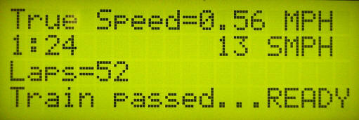
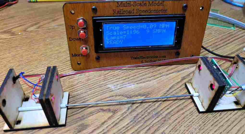
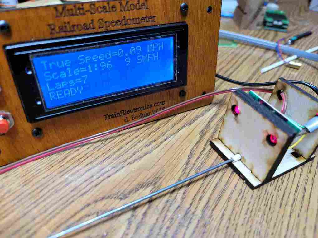
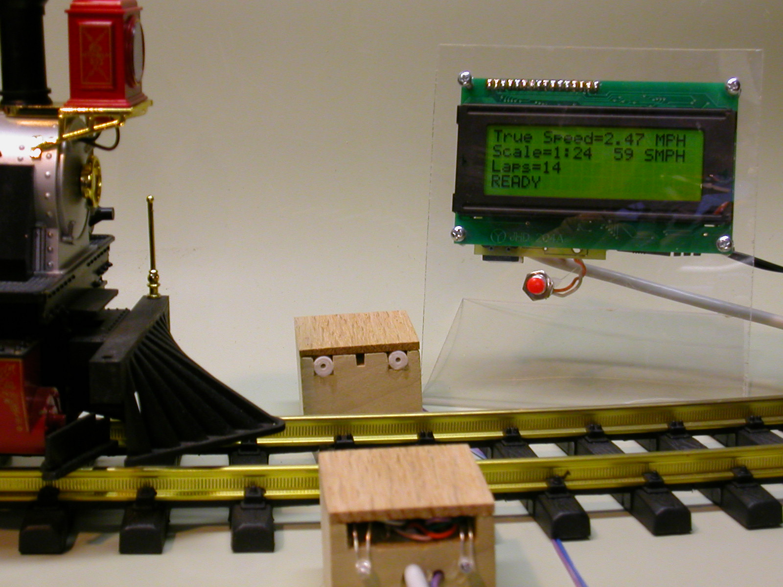
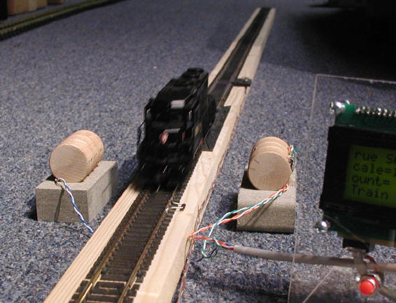
Using the speedometer 1. Once the scale is set just run your train through the sensors and the speed in real MPH (or KPH) will be on the first line of the display. It will be expressed as a decimal rounded to the nearest 1/100 of a mile (kilometer) per hour.
2. Scale (1:24, for example) and scale speed will be displayed on the 2nd line 3. If the sounder is activated the speed will also be “Beeped” out in code. First the number in the 10s place of the scale speed will beep out then the number in the ones place. If either is a zero a long beep will signify that. If you manage to reach a scale speed in excess of 99 mph the number of hundreds will be beeped out using a different sound. In the photo above the unit would beep once, signifying the 1 in 13, pause briefly then beep three time for the 3 in the ones place. |
|
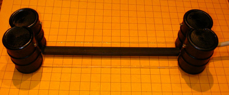
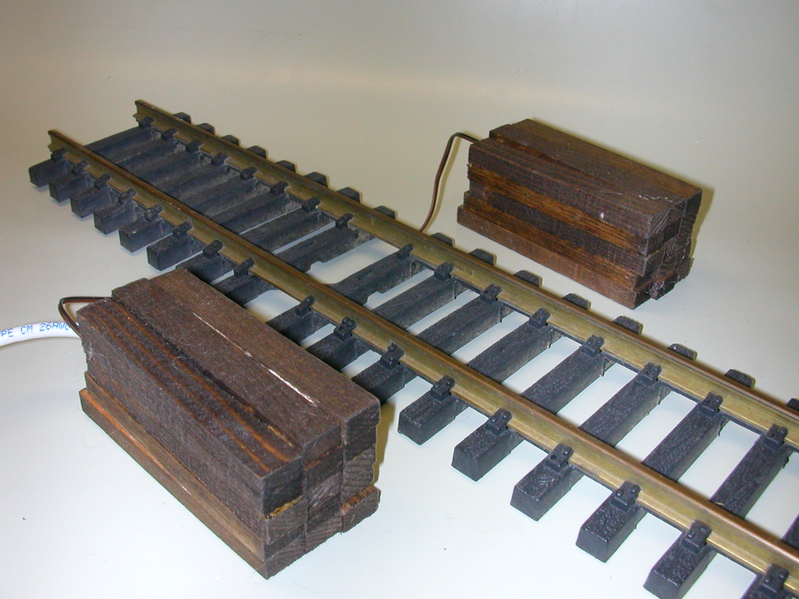
Sensor Options 1. The sensors for the MSTS are made up of a pair of infrared LEDs and a pair of infrared detectors. As mentioned above, the IR LEDs are pulsed at a frequency of 38 KHz and the detectors only respond to IR at that frequency. 2. The MSTS comes with one set of sensors that are mounted in a clear, plastic "U" shaped bracket. This mounting method allows users to place the sensors over the track so that they can easily be moved from place to place on the layout or to another layout entirely. 3. The sensors can be mounted in any number of trackside scenery items. The photos above show two "G" scale installations, one inside of two barrels and the other inside of two piles of railroad ties. 4. The sensors and IR LEDs are available separately. Detailed directions for mounting them are available here. |
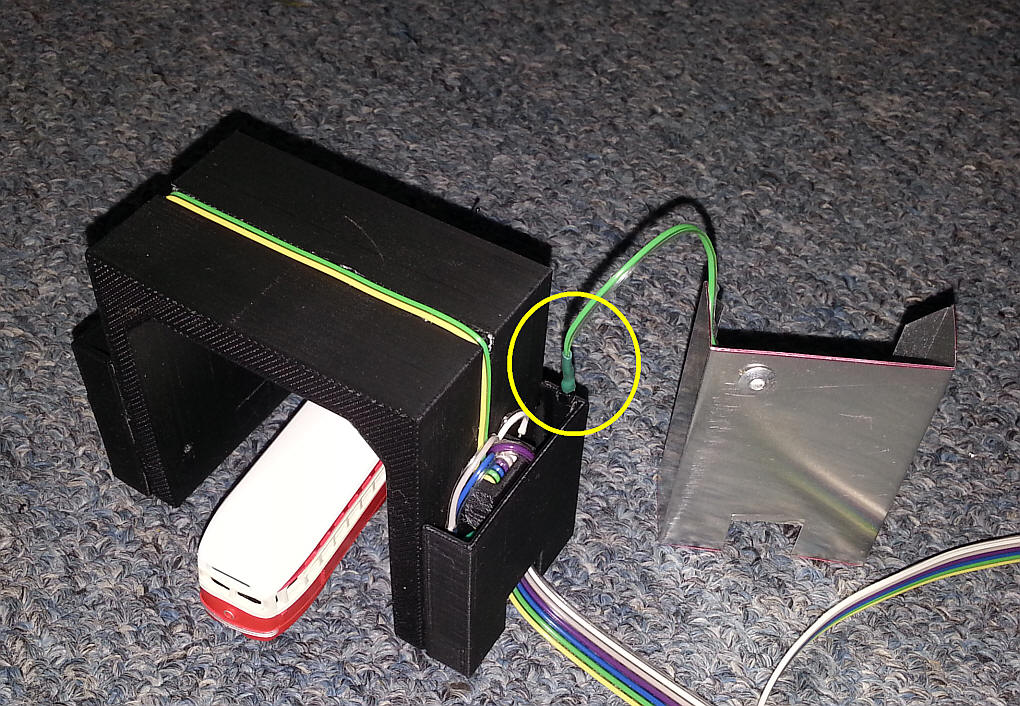
This photo shows a "S" scale sensor (on the left) that was made with a 3D printer. The aluminum panel on its right side allows the unit to work in a DCC environment as it shields the sensors from any interference produced by DCC pulses. The shield can be easily removed and unplugged from the ground lead if it is not needed.
|
| This is an "n" or "z" scale sensor tunnel. The
trolley shown is n-scale. The shield, useful when DCC signals
interfere with the sensor, is shown removed but still plugged into the
ground connection on the main sensor unit at the point circled in
yellow.
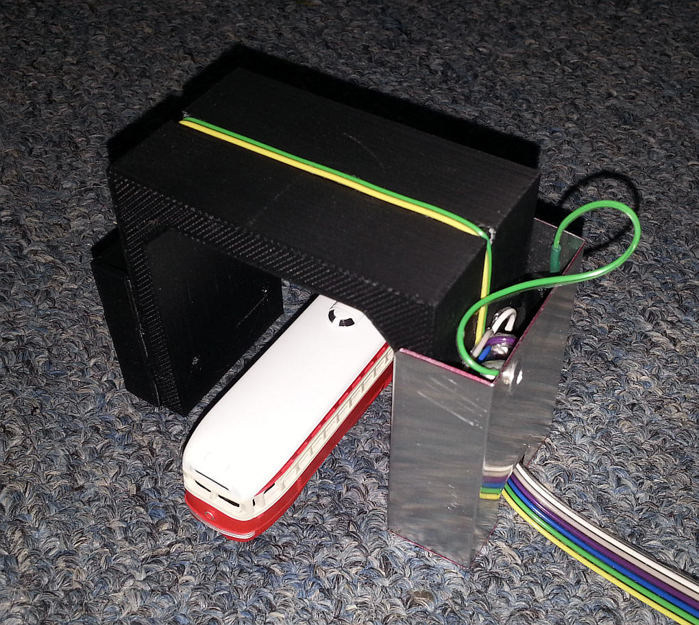
Here the shield is installed. Since it is made of very thin aluminum sheeting it must be handled carefully as it has sharp edges! If desired it can be painted or covered with black tape so that it will more closely match the tunnel.
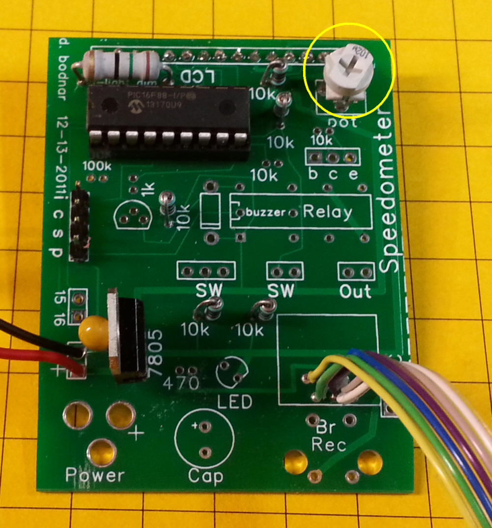
The small potentiometer (circled in yellow) can be used to adjust the contrast on the LCD display.
|
|
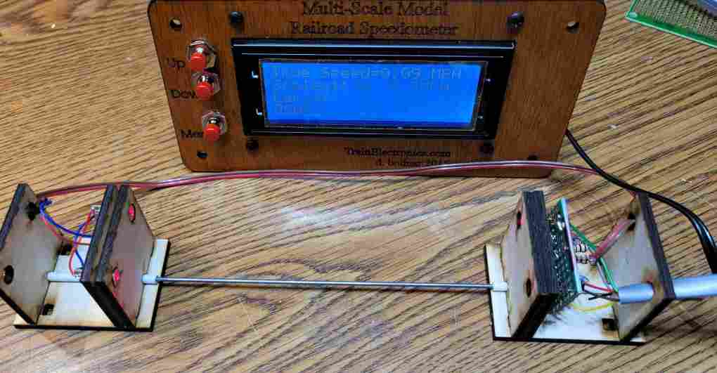
New Sensors - 2-1-2021 The original sensor system works well but can be difficult to align as it relies on infrared light which can't be seen. The new sensors use a pair of miniature red lasers and phototransistors. This allows you to easily see the alignment and make any needed adjustments.
|
| Here the two lasers are on the
left. If you look carefully you can see the red laser dot on the
sensors on the right. Take note of the piece of heavy wire that
joins the laser and sensor units. This is used for testing and
initial alignment and can be =removed once alignment has been made.
Here is another view of the display and sensor units.
This close up shows the two lasers.
Here the laser red dot can be seen hitting the phototransistors on the right.
This view of the back of the circuit board shows the connections to the UP / DOWN / MENU buttons. It also shows that the buzzer (white item in center of board) has a sticker on top of it - this is there to muffle the sound - if you want a much louder sound first make sure SOUND is ON in the menus then remove the sticker.
|
|
NOW AVAILABLE
-Pricing info is here:
http://www.trainelectronics.com/pricing.htm
email info@trainelectronics.com to order or if you would like more information. |
.JPG)
.JPG)
.JPG)