|
Introduction I came across a few higher power shields (that are described here: http://trainelectronics.com/DCC_Arduino/DCC++/) including one that has an advertised power capability of 43 amps. While I am a bit skeptical about this claim my tests show that it has no problem delivering 5 or more amps, more than enough for my purposes. I describe how this can be interfaced to the DCC++ controller in the link above. In order to make the use of this H-Bridge more convenient I decided to design a stand-alone DCC booster that would attach to a DCC signal and boost it before powering a track. The booster is designed to work with DCC++, Digitrax and other systems.
|
|
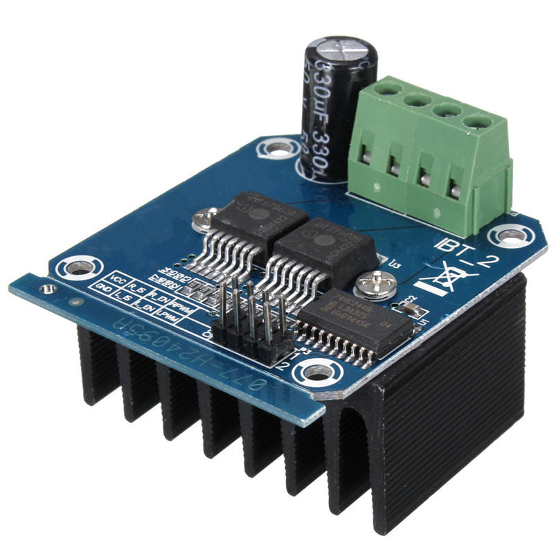
| Hardware - H-Bridge The H-Bridge is available from eBay, Amazon and other vendors - just search for "H-Bridge 43 amp BTS7960B". Make sure you get the unit that has two BTS7960B devices on it - each is 1/2 of an H-Bridge. The control signals go to the 8 pins on the front and the power in and power out wires go to the 4 pin screw terminal connector at the rear.
This H-Bridge and similar units do not
operate on the single PWM signal that most DCC systems provide.
It needs a right hand rotating PWM and a left hand PWM. To
change the single PWM signal to two a simple one transistor circuit
is needed. That circuit can be seen in the lower left corner
of the schematic (below). |
|
| Hardware - Arduino The H-Bridge can act as a DCC booster without much more than the Opto Coupler circuit (top left of the schematic) and the one transistor converter (lower left). The H-Bridge does hove an over current shutdown capability but it doesn't react until well over 30 amps are being drawn, way more than we are going to use. To get around this problem so that the system shuts down immediately if the track is shorted an Arduino Pro Mini has been added. The Arduino monitors the current sensing pin on the H-Bridge and can turn it off should it detect a high reading.
|
|
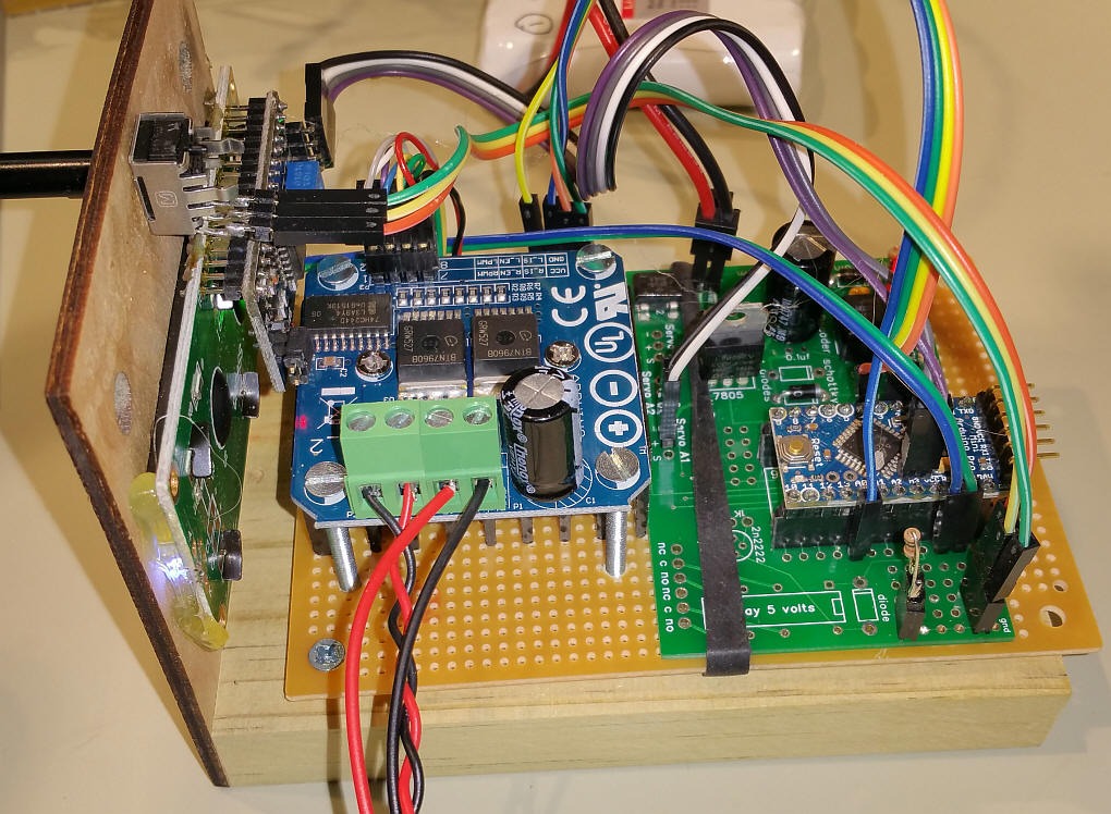
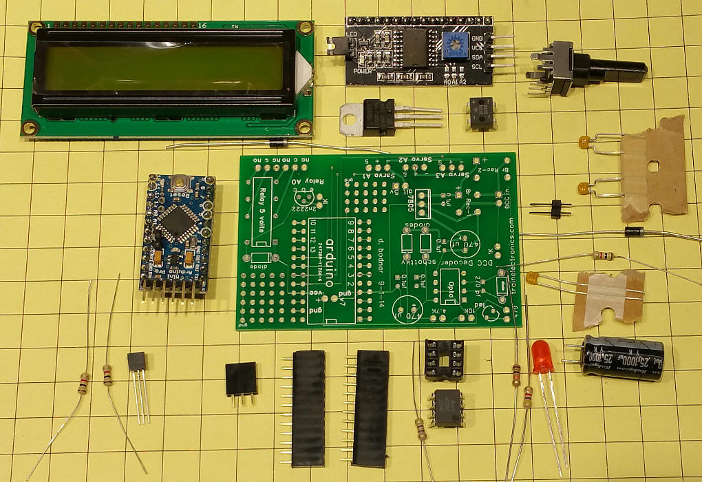
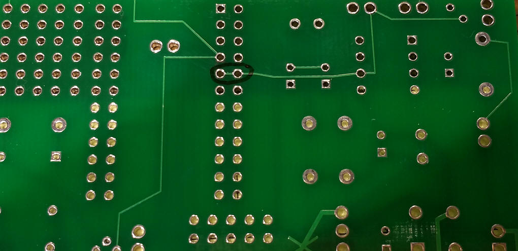
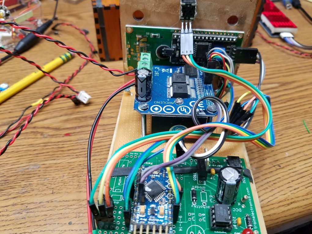
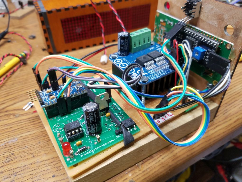
| Build Photos The unit shown in these photos was built on a circuit board that was originally designed as a DCC accessory decoder. It has most of the parts that are needed to make the booster. If you do use this board this trace needs to be cut.
It can be cut with a hobby knife or Dremel
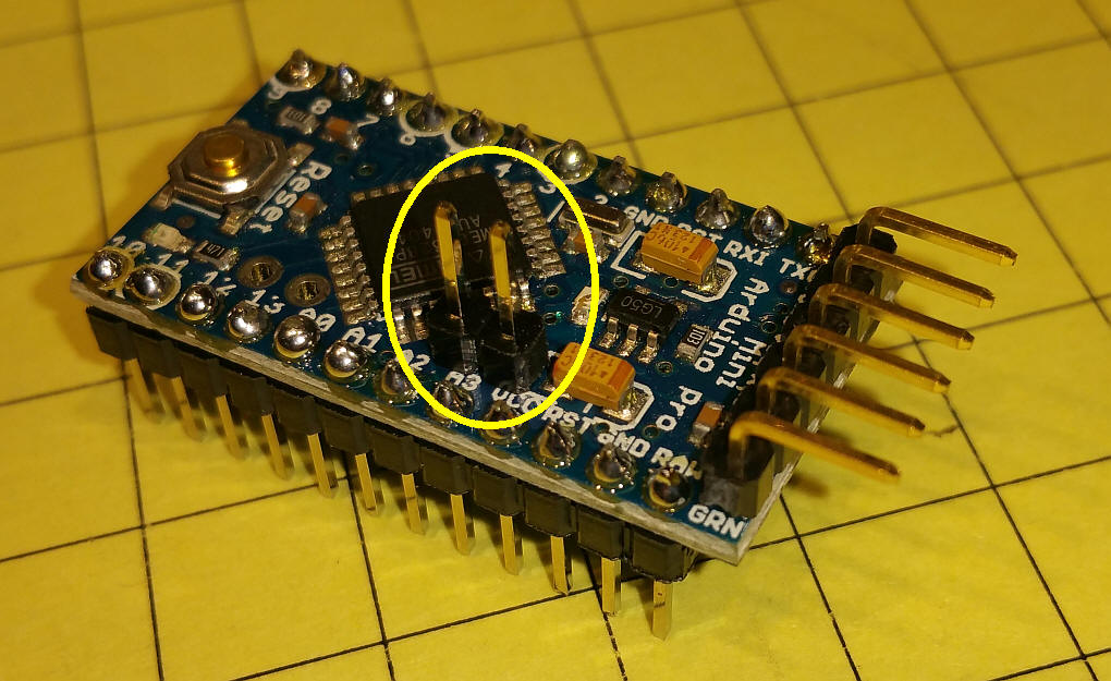
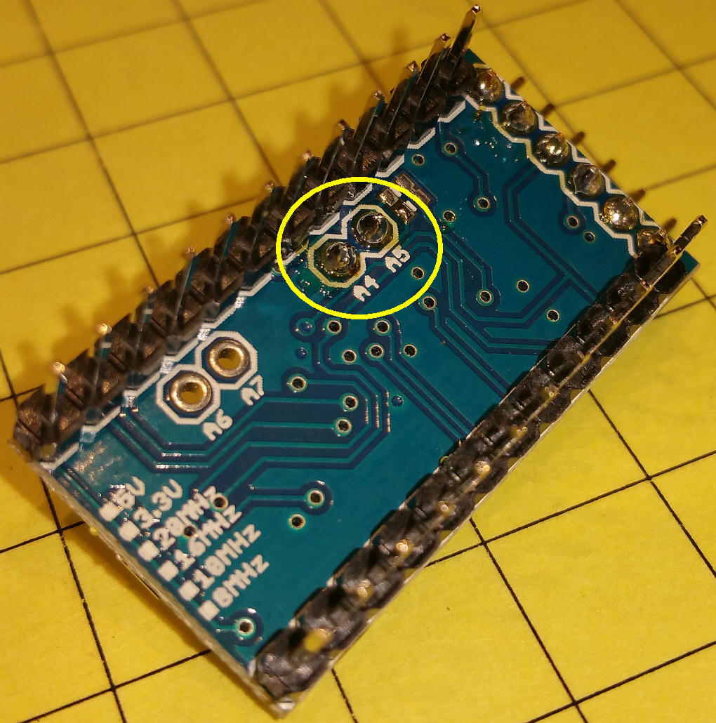
Note that two of the pins that are used by the I2C LCD display are not on the edge of the Arduino, but inside a few mm.
Here is a rear view of the LCD pins.
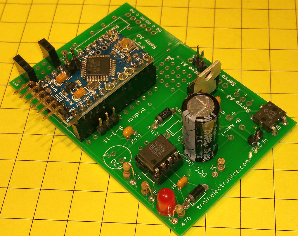
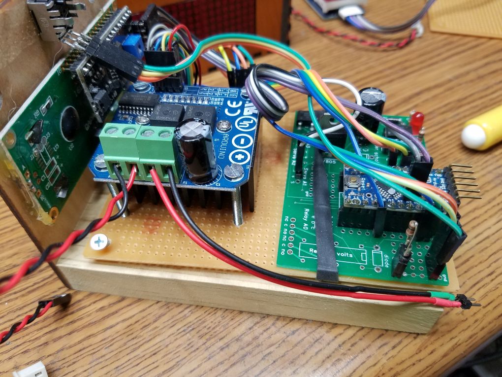
Here the board has most of the components installed. Note that a good many component areas are left unpopulated.
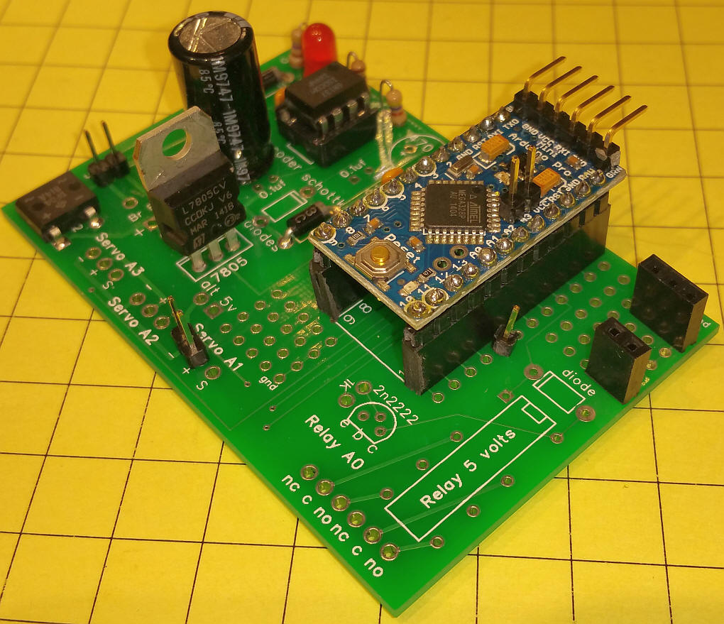
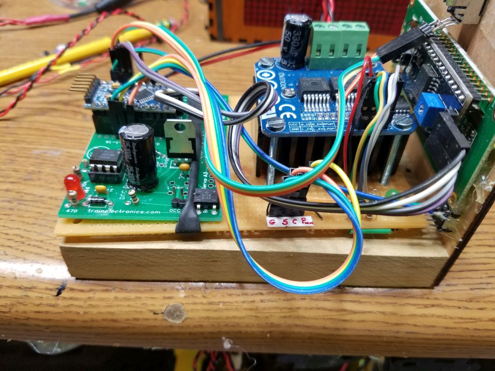
Here is another view.
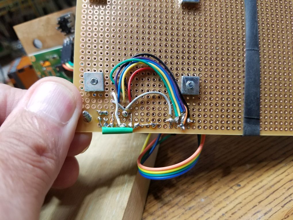
Here the connections for the potentiometer are shown.
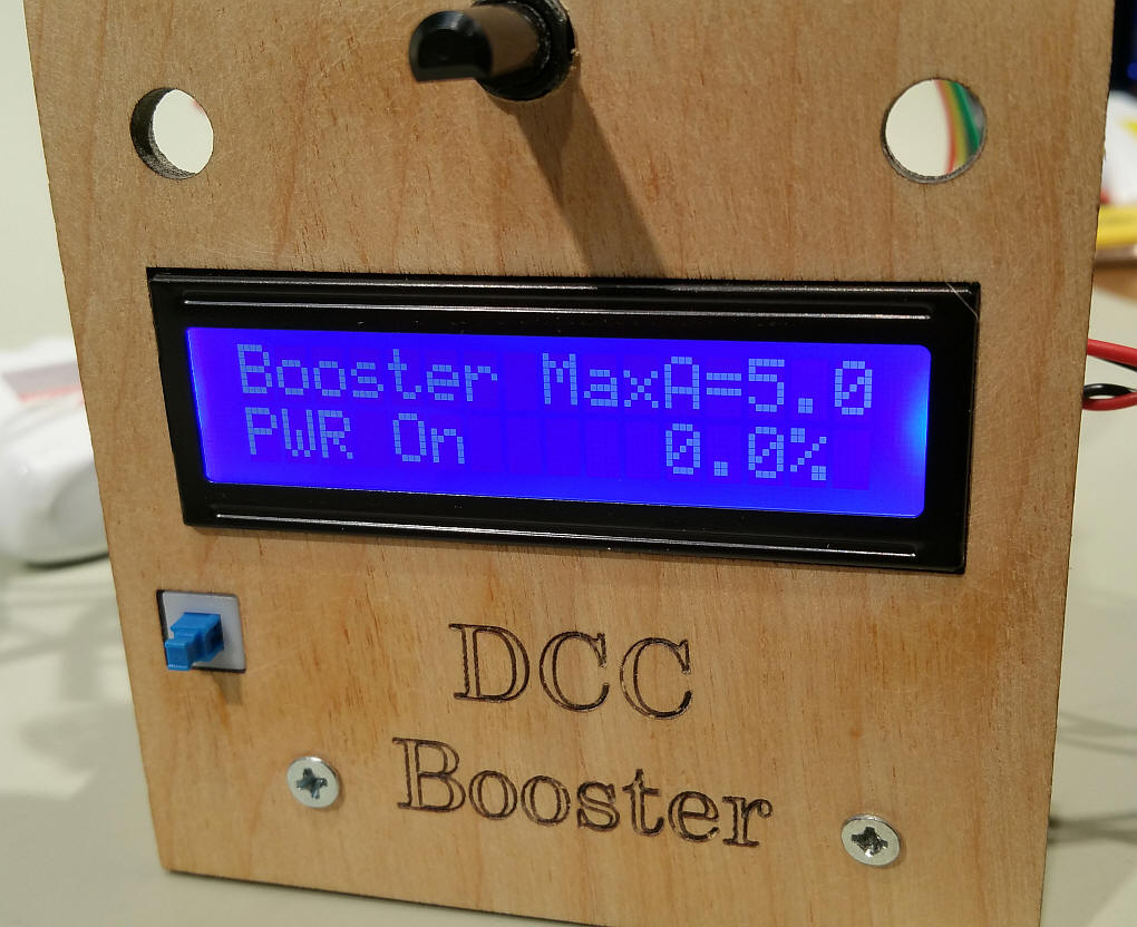
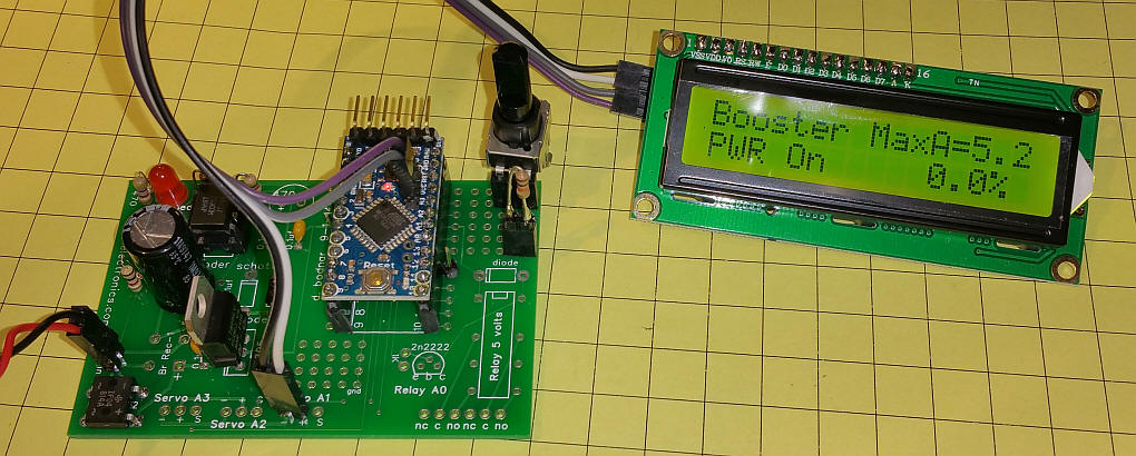
Here is the first test with the LCD display connected.
|
|
|
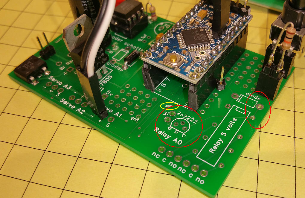
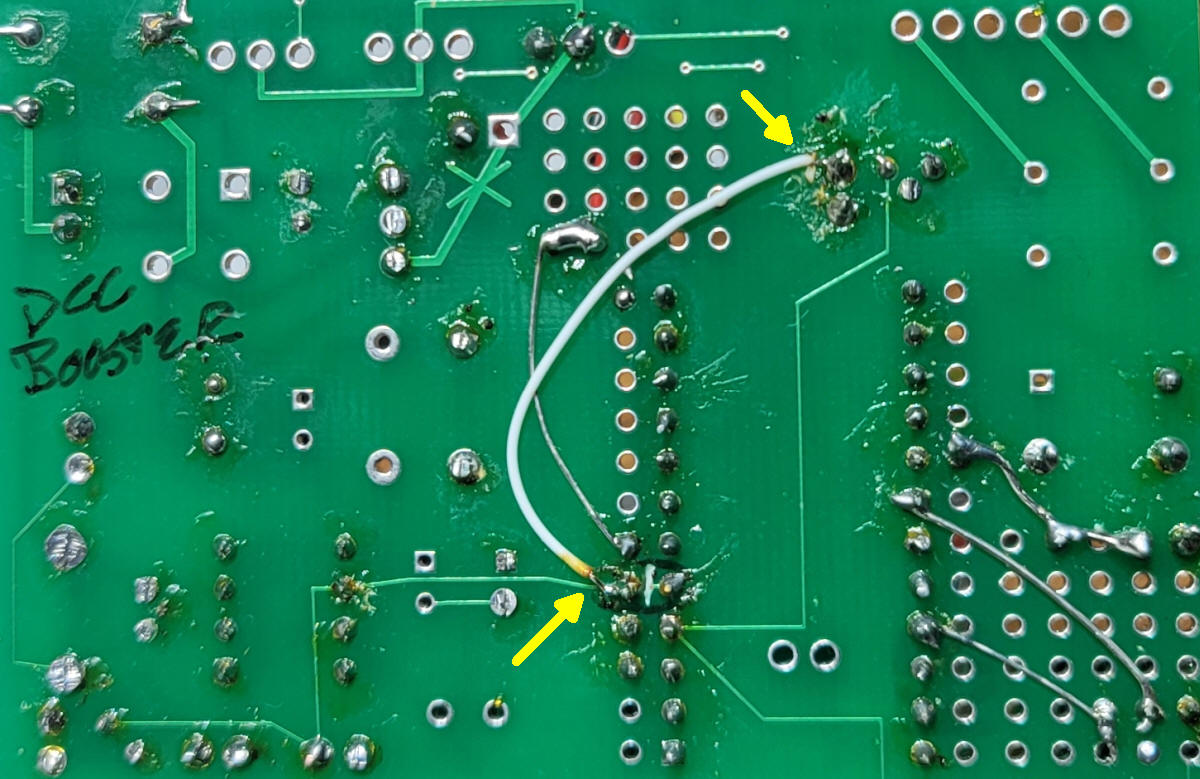
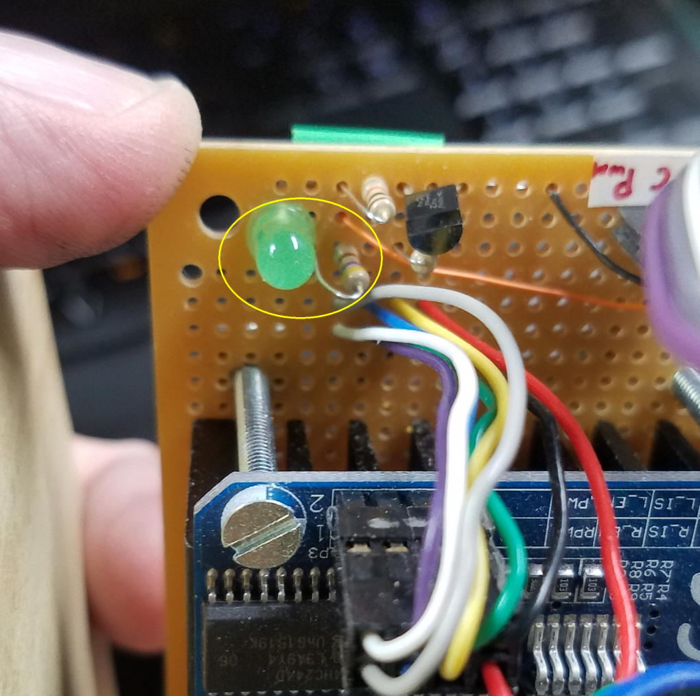
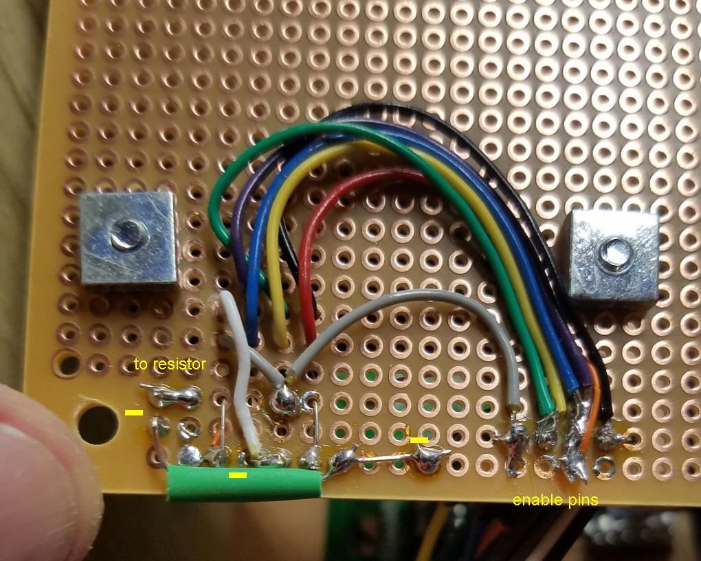
Putting the PWM Circuit on the Board
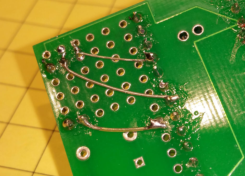
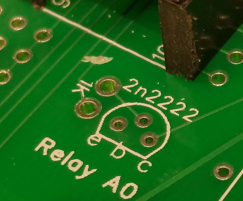
Here is a closer look at the trace I cut.
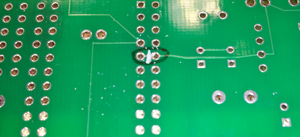
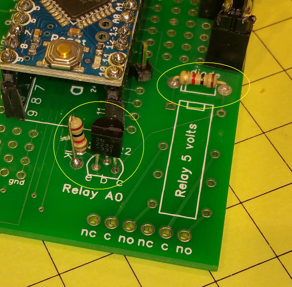
This shows the 2N2222 and two 1K resistors.
A jumper needs to be added between the output of the optocoupler (pin 5) and the resistor that connects to the base of the transistor. The white jumper shown here shows the connection.
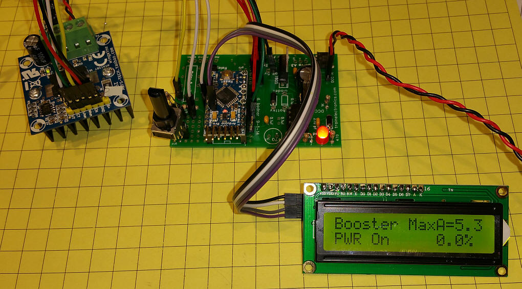
Here the booster is being tested with a 5 amp H-Bridge.
|
|
|
Software The software for the Arduino has several purposes. As mentioned earlier it can shut down the H-Bridge should a short circuit be detected. In addition a high current limit, say 5 or 7 amps, can be set. Once this is established it can give a percentage of that current that is being used. It can also shut down the H-Bridge should this limit be exceeded. The current limit is set with the potentiometer connected to pin A1 and the information on the H-Bridge's status is displayed on a 2 line x 16 character LCD display. This link is for two of the libraries that some folks have had difficulty with - it is a ZIP file containing both the LCD and WIRE libraries - unzip the files and put the LiquidCrystal2 and Wire folders in the libraries directory in the Arduino folder.
|
|
Version DCC_Booster_v1-4 /*
DCC Booster using the 43 amp H-Bridge from eBay & Amazon
*/
#include<EEPROM.h>
int LED = 13; // LED to blink when DCC packets are sent in loop
int PowerOn = 3; // pin to turn booster on/off
int Pot1 = 1;
float PotReading = 0;
int CurrentPin = 0;
int CurrentPinReading = 0;
int SetPotFlag = 0;
float version = 1.4;
#include <Wire.h>
#include <LCD.h>
#include <LiquidCrystal_I2C.h>
#define I2C_ADDR 0x27 // <<----- Add your address here. Find it from I2C Scanner
#define BACKLIGHT_PIN 3
#define En_pin 2
#define Rw_pin 1
#define Rs_pin 0
#define D4_pin 4
#define D5_pin 5
#define D6_pin 6
#define D7_pin 7
LiquidCrystal_I2C lcd(I2C_ADDR, En_pin, Rw_pin, Rs_pin, D4_pin, D5_pin, D6_pin, D7_pin);
unsigned long time;
unsigned long now;
long cAverage = 0;
int avgTimes = 400;
int lastAverage = 0;
int resetFlag = 0;
float percentage = 0;
int temp1 = 0;
void setup() {
delay(500);
pinMode(LED, OUTPUT);
pinMode(PowerOn, OUTPUT );
lcd.begin (16, 2); // LCD is 16 characters x 2 lines
lcd.setBacklightPin(BACKLIGHT_PIN, POSITIVE);
lcd.setBacklight(HIGH); // Switch on the backlight
lcd.home (); // go home
Serial.begin (115200);
lcd.setCursor(0, 0);
lcd.print("DCC Booster");
lcd.setCursor(0, 1);
lcd.print("2-11-16 - v");
lcd.print(version, 1);
Serial.print("2-11-2016 version ");
Serial.println(version, 1);
delay(1000);
lcd.clear();
turnPowerOn();
delay(500);
now = millis();
}
// NOTE: about 0.014 amps / digit of reading with 10K resistor on sense line
void loop() {
PotReading = analogRead(Pot1);
PotReading = PotReading / 100;
lcd.setCursor(12, 0);
lcd.print(PotReading, 1);
lcd.print(" ");
lcd.setCursor(7, 0);
lcd.print("MaxA=");
showPercentage();
resetFlag++;
if (resetFlag >= 100) {
resetFlag = 0;
}
cAverage = 0;
for (int xx = 0; xx < avgTimes ; xx++) {
CurrentPinReading = analogRead(CurrentPin);
if (CurrentPinReading >= 1000) {
Serial.println("STOPPPPPPPPPPPPPPPPPPPPPPING");
turnPowerOff();
}
cAverage = cAverage + CurrentPinReading;
}
CurrentPinReading = cAverage / avgTimes;
if (CurrentPinReading != lastAverage) {
if (millis() - now >= 450) { // only update LCD every 1/2 second to limit flicker
lcd.setCursor(0, 0);
lcd.print("C=");
lcd.print(CurrentPinReading);
lcd.print(" ");
}
turnPowerOn();
}
lastAverage = CurrentPinReading; // keep for compare & print
} //END LOOP
void showPercentage()
{
percentage = (CurrentPinReading * 0.0105) / PotReading; // was 0.014
percentage = percentage * 100;
if (millis() - now >= 500) // only update LCD every 1/2 second to limit flicker
{
lcd.setCursor(9, 1);
lcd.print(percentage,1);
lcd.print("% ");
now = millis();
}
if (percentage > 100) turnPowerOff();
}
void turnPowerOff() {
digitalWrite(PowerOn, LOW);
lcd.setCursor(0, 1);
lcd.print("PWR OFF-2 sec");
delay(2000);
turnPowerOn();
lcd.setCursor(0, 1);
lcd.print(" ");
}
void turnPowerOn() {
digitalWrite(PowerOn, HIGH);
lcd.setCursor(0, 1);
lcd.print("PWR On");
}
|