G-Scale Drag Strip Controller
Revised 07-23-08

The objective of this project is to design and construct a controller that will manage a G-Scale drag strip where two locomotives will race each other over a fixed distance.
The controller will make sure that the two competing engines are staged properly at the start and that they both start fairly after the "Christmas Tree" lights have reached green.
The controller will determine the winner and will display the reaction time of each competitor and the time to complete the run.


The controller is ready to go! 
Click here for setup and testing information.


Latest News:  Several decisions have been made that will necessitate some significant changes to the software and hardware:
  1. The "Final" prototype circuit has been completed, tested and duplicated
  2. A routine has been added to test the four sensors.  If the "Start" button is pressed during the initial copyright screen the test screen appears.
  3. The software is nearing completion and should only require minor "tweaks" to finalize it
  4. Testing of a new sensor design is progressing well.
  5. Custom circuit boards for the microcontroller and power transistor circuit have been designed and ordered.
  6. Two 24 volt / 6.5 amp power supplies were purchased and used for testing.


Stay tuned!


Operational Scenario

Two parallel tracks are set up on a level surface.  A few feet from one end a "Christmas Tree" light pole and two IR sensors are placed between the tracks.  Near the other end of the track two more IR sensors are placed to determine the winner.  Sufficient track is left after the end sensors to allow competitors to bring their engines to a safe stop.  It is recommended that diodes be placed in the track to prevent trains from running off the end. 

A five conductor cable connects the far end sensors to the controller.  A second five conductor cable connects the start sensors and a ten conductor cable connects the "Christmas Tree" lights to the controller.  The controller itself connects to 7-12 volts DC and has two buttons on it, one labeled Start and one labeled Reset.  A separate power supply that is appropriate for the voltage of the Christmas Tree's bulbs attaches directly to the lighting circuit.  If LEDs are used for the Christmas Tree the same power supply that powers the controller can be used.

Each track is connected to its own power supply.  The competitors control starting and stopping of the engines and use the throttle to determine their speed.

To start a race:

  • The race official presses the Reset button on the controller. 
  • The Blue lights on the Christmas Tree flash 3 times indicating a successful reset. 
  • The Blue lights remain lighted to signify that neither engine has been staged.
  • Engines are placed on the track behind the tree and moved forward until the Red light in their lane illuminates. 
  • Each engine is then moved backwards until the Red light in its lane goes out.  This is the start position.
  • When both engines have been properly staged both Blue lights are off.
  • The race official presses the Start button on the controller.
  • The Christmas Tree begins to signal the start of the race.  The top Amber light lights, 0.5 seconds later it goes out and the second Amber light lights, 0.5 seconds later it goes out and the third Amber light lights, 0.5 seconds later it goes out and the Green light lights.
  • When the Green lights light the race begins and each competitor starts their engine.
  • The controller notes if either engine crosses the start sensor before the Green lights light.  If this happens the Red light in that lane lights and that lane is disqualified.
  • Timing for each lane starts when the first sensor is crossed and stops when each engine crosses the end sensor.
  • After the race the Blue light atop the tree lights to indicate the winning lane.
  • The results are not reported until both end sensors are crossed.  This will necessitate manually breaking one of the end beams if one engine breaks down.
  • The LCD display gives the reaction time and total time (in seconds, tenths and hundredths) for each lane.
  • Pressing the Reset button clears all data and restarts the system.
Hardware
  •  The Christmas Tree light pole will be made up of two identical columns of lights.  There will be a blue light at the top, then three amber lights followed by a green light and a red light.  The blue light at the top will illuminate to indicate the winner of the race.
  •  For outside use the lights will be replaced by 12 volt colored incandescent bulbs such as those used in landscape wiring.  The higher current consumption of these bulbs will necessitate the use of 8 power transistors (TIP101, Darlingtons)
  •  Each competitor will start their engine by applying power to their track.  The power source and connections will be completely independent and not connected to the controller in any way
  •  Four sensors will be installed on the track.  Two at the start (one for each lane) and two at the finish.
  •  Pulsed infrared light sensors will be used so that ambient IR will not less of a problem.  As long as the sensors are not facing direct sunlight they should work well.  Note that flash photography can temporarily "blind" the sensors giving erroneous results. 
  •  Each set of sensors will be composed of several parts.  Between the tracks will be the two IR detectors.  On the outside of each of the tracks individual IR LEDs will be aimed at the sensors.
  •  If an engine crosses the start sensor before the green light is lit that competitor will be disqualified.  This will be indicated by that lane's red light lighting
  •  The blue light on the Christmas Tree will light to show the winner's lane.  The winner will also be shown on the LCD screen along with each lane's reaction time and total run time.
  •  The controller will need the following input and output channels:
    • 6 for communicating with the LCD display
    • 1 push button switch input for starting the race
    • 1 push button switch input for resetting the system
    • 2 IR inputs for staging and to start timing (one for each lane)
    • 2 IR inputs for the finish line (one for each lane)
    • 1 IR LED output for 38 KHz pulses
    • 2 light outputs for the blue lights (separate output for each lane)
    • 3 light outputs for the amber lights (both lanes wired in parallel)
    • 1 light output for the green lights (both lanes wired in parallel)
    • 2 light outputs for the red lights (separate output for each lane)
Other Thoughts
  • Should the timing start when the engine hits the first sensor (as described above) or when the green light lights? [Note: currently have it set to start when the green light lights]
  • Should any voltage be allowed or should both engines use the same model power supply? [This should be determined by the "rules committee"]
  • Battery operated trains could also compete.  How is power to those managed?
  • The controller will be in a box about 3" wide and 6" long.  It might make sense to mount the Tree on top of it and have the start sensors be partially mounted in it as well.  This would cut down on the number of wires. [Note: this is what has been done on the LED prototype - the incandescent bulb unit is separate]
  • The sensors will be located close to the top of the rail but they still could detect either the front wheels, as intended, or the cow catcher or some other protuberance at the front.  This should not be a problem as long as the start and finish sensors are at the exact same height.
  • An RJ12 connector (similar to those used with computer Ethernet cable or phone cables but with 6 contacts) could be used to connect the end sensors to the controller [That is what has been done on the prototype unit]
  • A 4 line x 20 character LCD display should be added and used to display the results of each race. [done]
  • The microcontroller is also capable of determining and reporting the average speed for each run but variations in track length make this problematic. 
  • A second set of sensors could be added near the finish to determine the ending speed but this would add to the complexity and cost of the system as we have used all of the 28 pins that are available on the chip we are currently using.
  • Similarly, a second set of sensors could be used at the start to more accurately set staging.
  • To achieve extreme accuracy the IR LEDs can be replaced with laser diode modules.  I have experimented with these and they work VERY well but would add to the total cost. [Note: the prototype works very well with the IR LEDs - Lasers might only be needed if two sets of sensors were used for staging at the start]
  • The race track can be of any convenient length.  A 1/24 scale 1/4 mile would use 55 feet of track (5280 / 4 / 24).  A scale 1/8 mile track would be 27.5 feet long.
  • Unless a good bit of track is laid after the finish line cut track with diodes is highly recommended as it makes it much easier to stop the trains at the end.  They can also be retrieved but running them in reverse, a convenient feature, especially during testing!
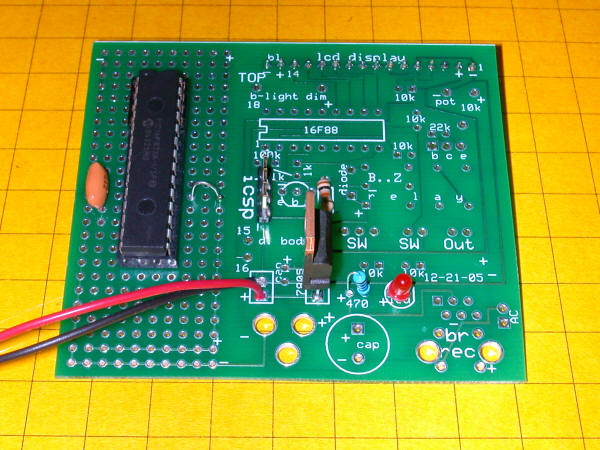
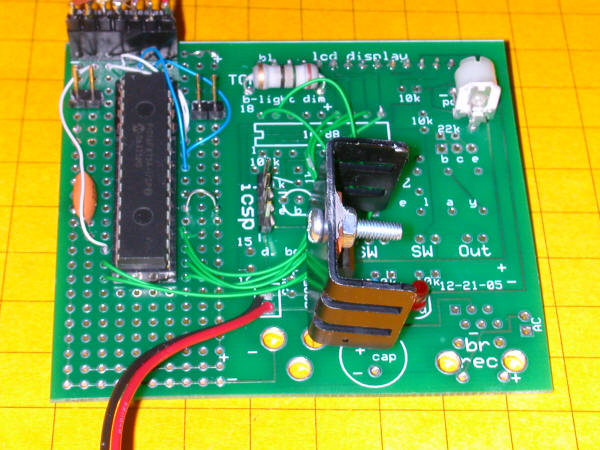
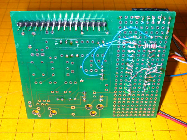
Latest Prototype Photos

This unit utilizes a PIC 16f873A processor that is mounted on a prototyping area that I left to the side of some of my speedometer circuit boards.  This allows quick prototyping as the right side of the board allows for quick connections to a regulated power supply and programming pins.  The PIC is to the left - the device to its left is a 4 MHz resonator.

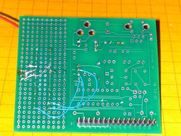
Here is the back of the board - in its current state the chip can be programmed.

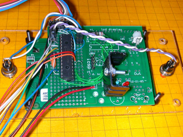
The components that are needed to drive the LCD display have been added in this photo.  The pot in the upper right is used to adjust the display's contrast.  The large resistor at top center is the current limiter for the backlight on the LCD.

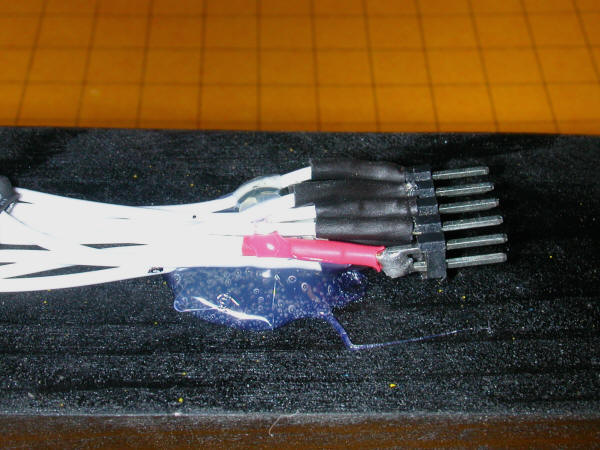
A heat sink has been added to the 7805 regulator and a 7 pin header at top left connects to the sensors.

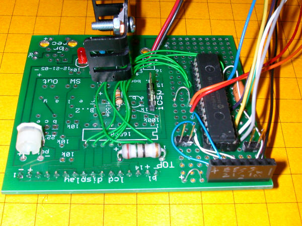
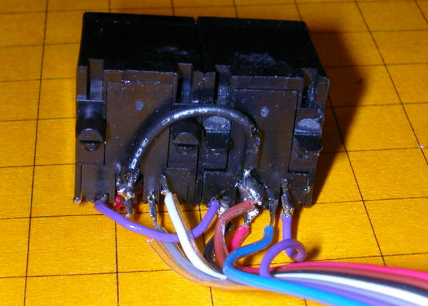
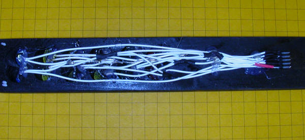
Here the connector for the sensors can be seen more clearly.  The colored array of wires coming from around the chip connects to the Christmas Tree driver box.

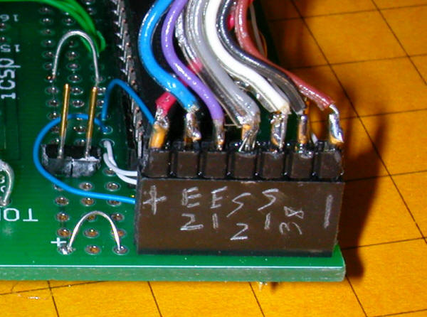
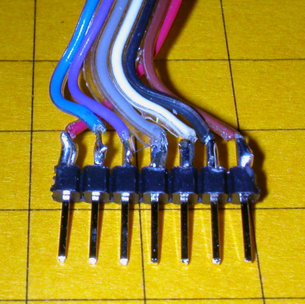
A tight close-up of the wiring of the sensor cable.

Another view of the finished board, front...

... and back.

Another close-up of the sensor cable.

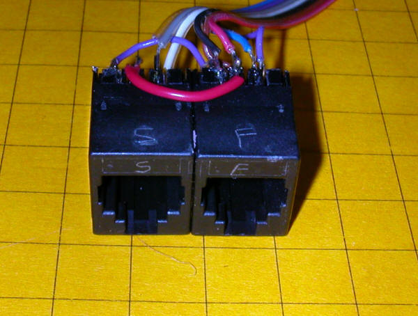
The other end of the sensor cable terminates in two female RJ-11 connectors.  These will be mounted on the control box so that the sensors can be quickly connected or disconnected.
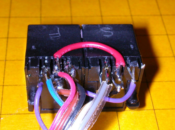
Wiring close-up.

And another.

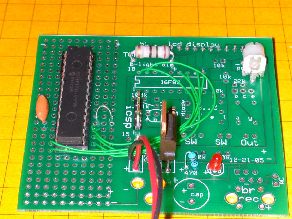
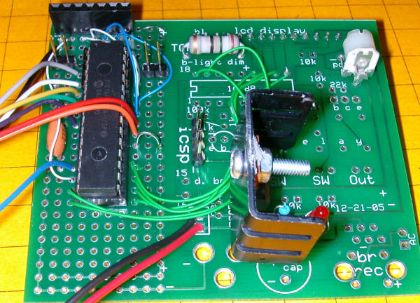
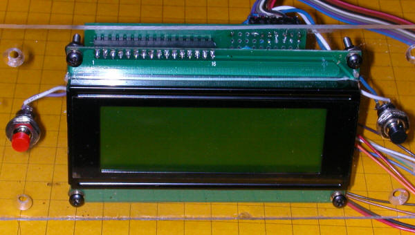
Here the LCD has been attached.  The button (red on left) is RESET.  The black button on the right is START.

A back view with LCD and switches.

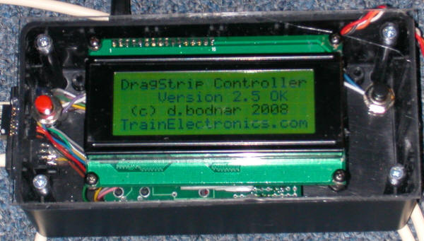
The opening screen of the display.

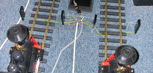
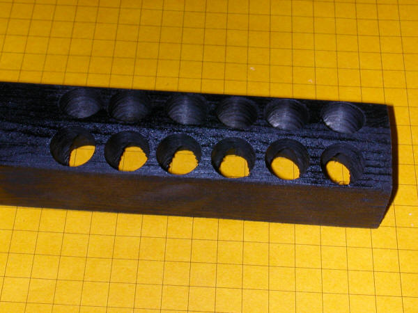
This view shows the start line.  The two start sensors are at the top.  The two black blocks in the center contain IR detectors while the outer two blocks contain IR LEDs.  The Christmas tree connector is shown at the very top.

This view is from almost directly overhead.


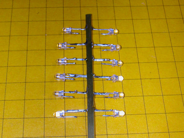
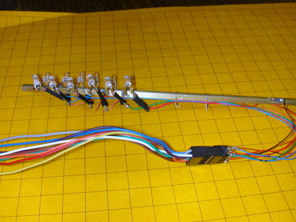
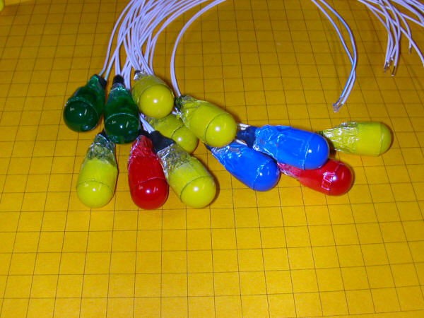
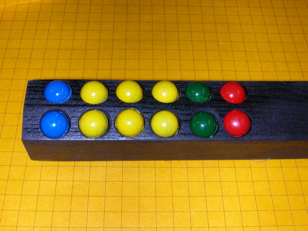
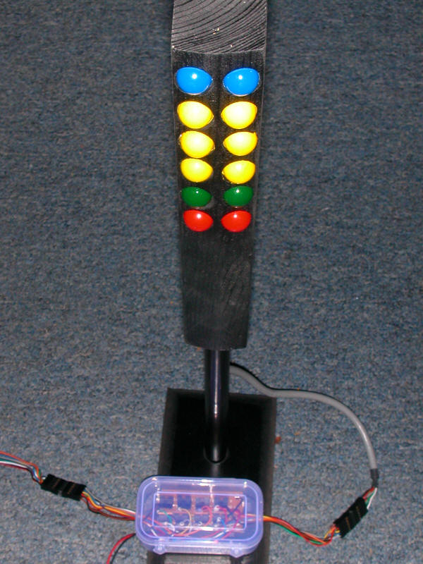
Prototype #1 Photos

The Christmas Tree is made from 12 lights.  Two blue at the top then three pairs of amber, a pair of green and two red at the bottom. 

The negative lead from each LED is soldered directly to the square brass support in the center.  Each positive lead has a 200 ohm 1/8 watt resistor soldered to it.  This is needed to limit current to the LEDs.

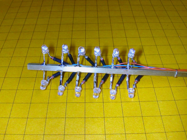
A 10 conductor plug was added to accommodate the wires from the Christmas Tree

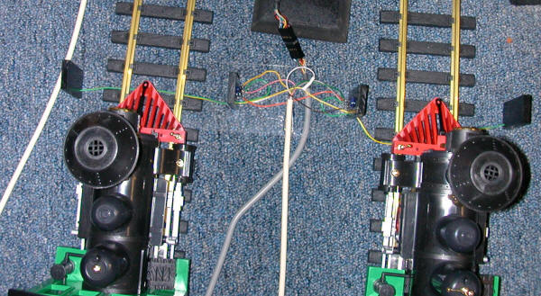
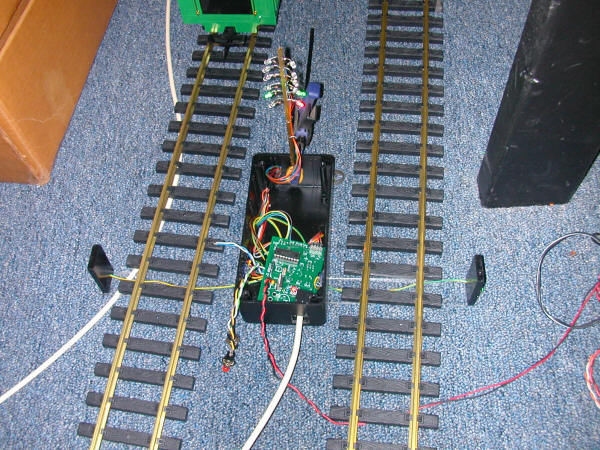
This view shows the start with the controller in the black box in the center.  The Christmas Tree is at its top and the two sensors extend from the sides of the box.

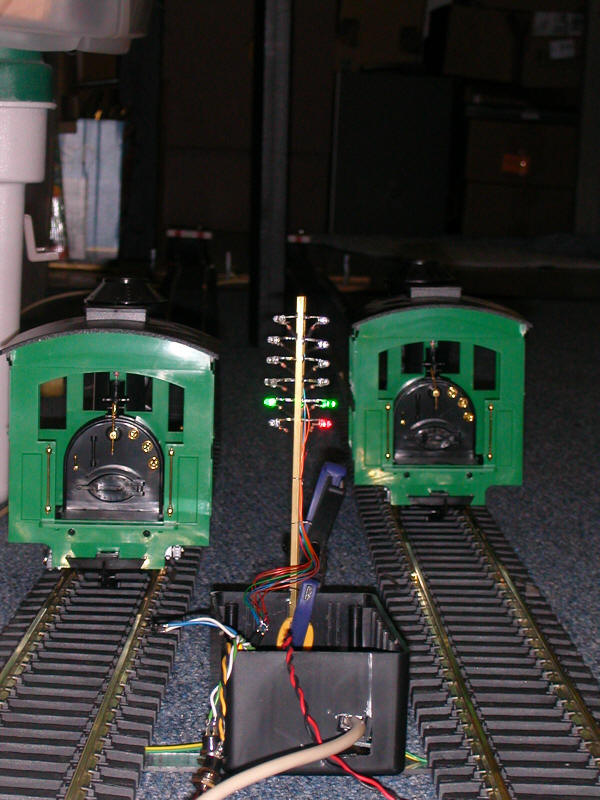
A green lights signal the start of a race.

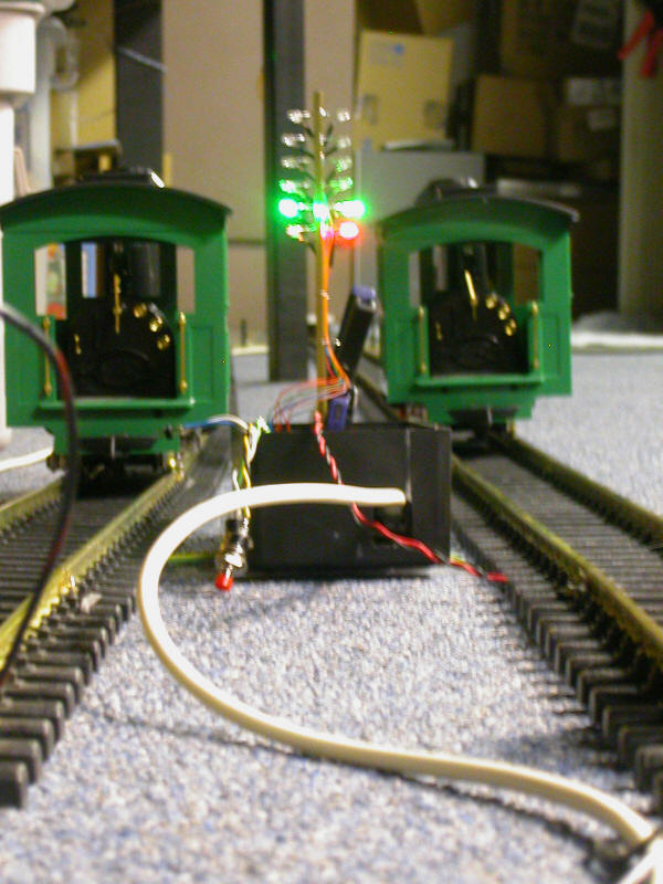
In this slightly blurred photo the red light in the right lane is lit indicating that the right engine false started.

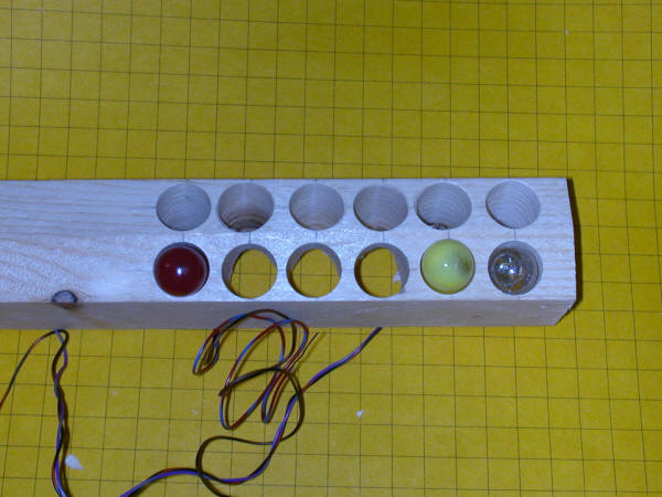
Incandescent Bulb "Christmas Tree"

To allow proper testing of the circuitry with 12 volt "Malibu" type bulbs a wooden tree support was made from a scrap of 2" x 2" lumber.

The face of the board that shows the bulbs has been tapered 10 degrees on each side so that the bulbs point towards one lane or the other.

The taper can be seen more clearly in this photo.  The holes were drilled with a 5/8" Forstner bit with the drill press table tilted to 10 degrees.  The bulbs are just a bit over 1/2" in diameter so they easily fit in the holes in the block.

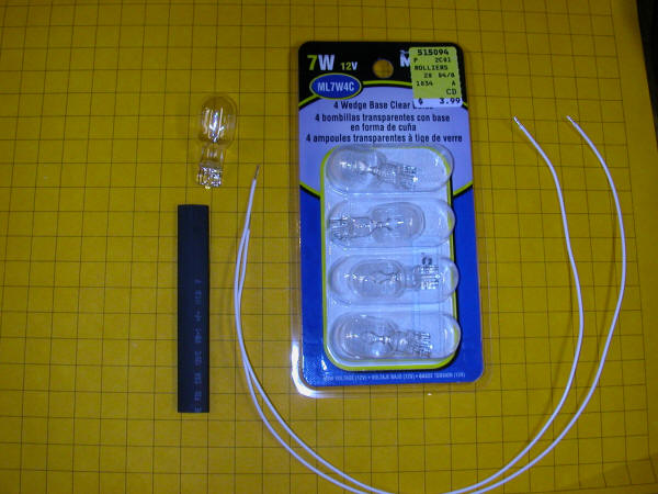
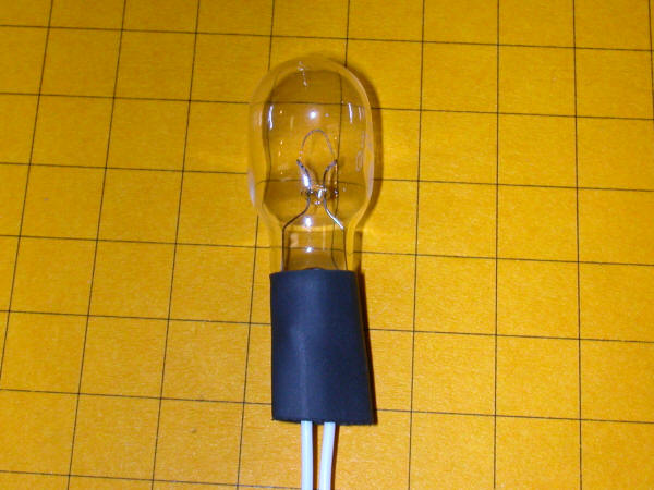
Bulb Preparation

Wires need to be connected to the bases of the Malibu bulbs before mounting them in the "tree".

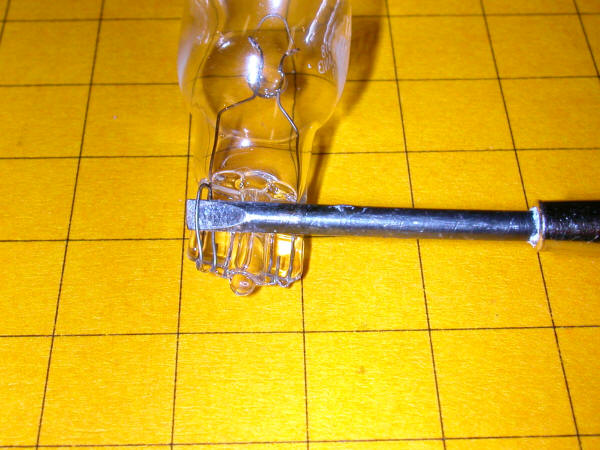
The bulb's contacts can be seen in the photo below.  Solder will not adhere to the contacts.  In order to connect the wires to the contacts use a small screwdriver to spread each contact to that the stripped end of the wire can fit between the loop of wire.

The wires have been pushed through the contact wires and folded over.

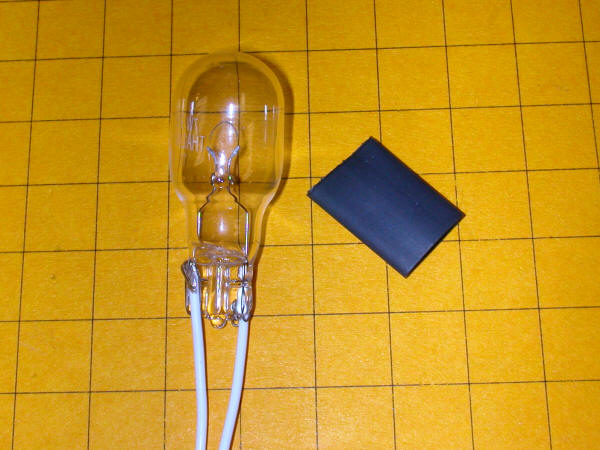
A piece of 1/4" inch heat shrink tubing is slid over the end of the bulb and the connecting wires.

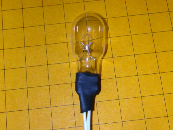
A secure connection is made after shrinking the tubing.

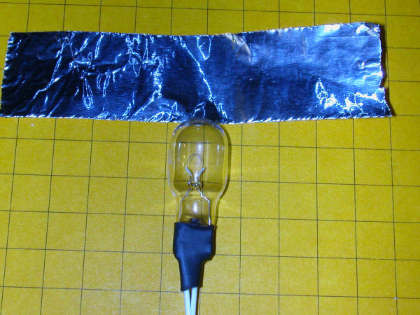
The bulb can be brightened a good bit by wrapping the back 2/3 of the glass in foil.

The foil is folded over the end and secured with a small piece of tape.

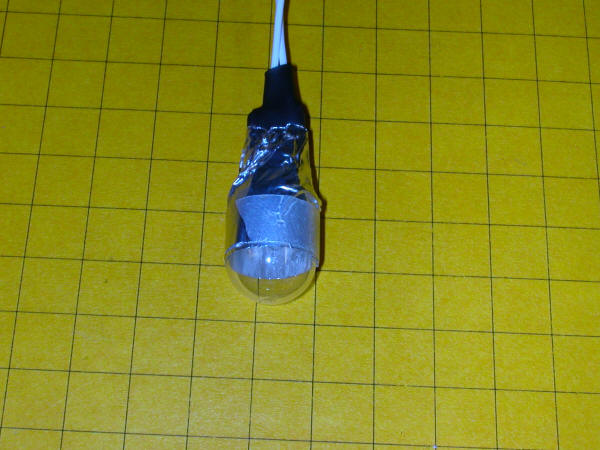
Here you can see how the foil acts as a reflector.

The bulbs are temporarily mounted in the "tree".

Now they are ready for painting!

A light coat of spray paint did the trick.

Flat black paint for the base.

The bulbs are inserted from the rear and hot melt glued in place.

The wiring for the bulbs terminates in a 10 conductor plug.

Here is a close-up of the connector.

The finished "Christmas Tree" has a wooden base and a plastic pipe support.

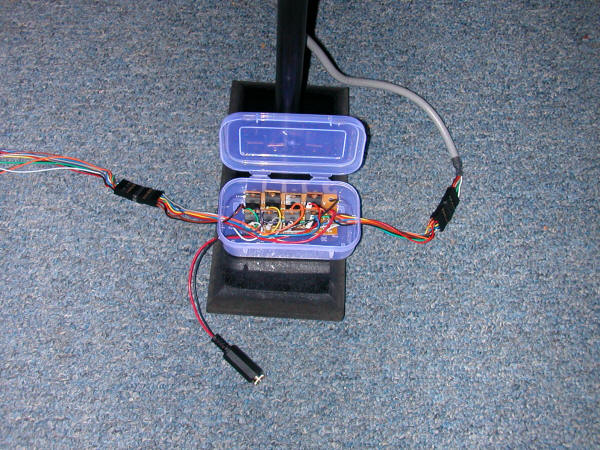
The box at the bottom holds the eight TIP101 Darlington transistors that drive the bulbs.  The connector at the very bottom is for the 12 volt power that goes to the bulbs.  Note that the power supply must be DC even though the bulbs themselves will work on DC or AC.  The voltage of this power supply should be adjusted to match the voltage of the bulbs.


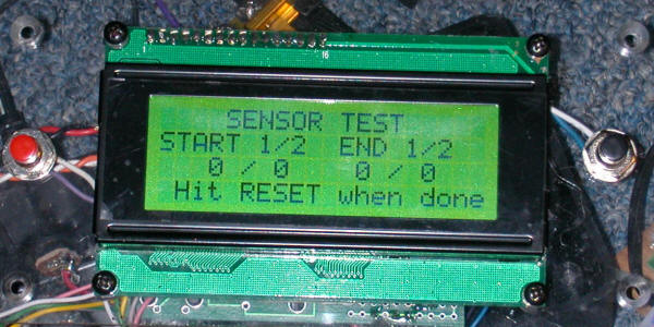
Sensor Test Routine

A routine has been added that allows the operator to confirm that the two start and the two finish sensor are working properly.  To access this routine press the "Start" button while the copyright screen is being displayed.

The first set of zeros in the third line shows the number of times the test routine has gone through its loop while the sensor was being blocked. while the second set of zeros shows the end sensors.

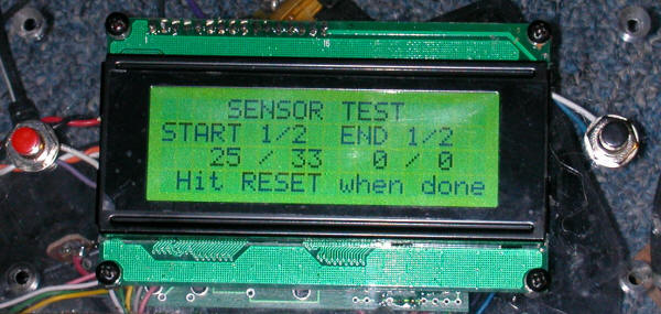
Here you see that the start sensor in lane 1 has been blocked while the test routine went through 25 cycles and the lane 2 sensor was blocked for a bit more time as it shows 33 cycles.  The count goes from 0-255 when it resets to 0 and starts counting again.  This method of testing is useful as you can observe if outside interference gives false readings.  If you enter the test routing and the counts remain at zero until you manually break the IR beam no outside interference is being seen.  On the other hand, if one or more of the sensors shows random increases sunlight or some other source of interference may be causing a problem.  Remember that flash photography can briefly blind the sensors causing erroneous readings. 

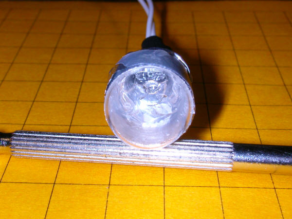
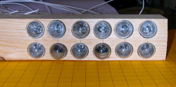
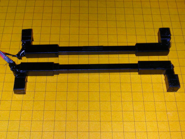
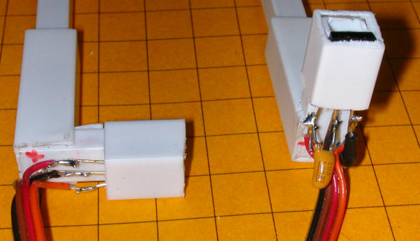
New Sensor Design

A revised sensor design places the emitter and detector lower and farther to the side.  This design also fits nicely between the ties.  In this photo one sensor is shown.  The emitter is to the right and the detector to the left.

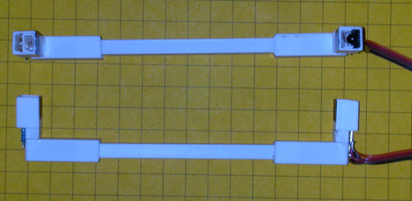
Here is a pair of sensors after painting.

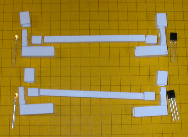
Each sensor is made of 9 pieces of styrene, one IR led and one IR detector.  In this photo two pieces of styrene have been glued together to make a right angle piece.

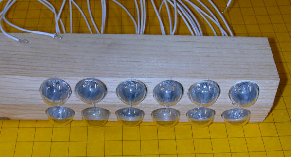
These sensors are complete except for painting

This view is of the IR led end of the sensors.

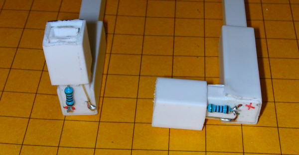
Here are the detectors.  Note the capacitor on the right detector.  It has not yet been added to the left unit.
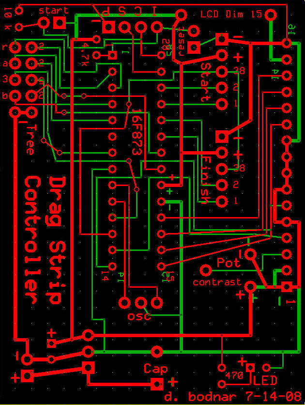
 

Custom Printed Circuit Boards

Once the circuit has been prototyped and tested a pair of custom circuit boards can be made.  The layout below is for the main microcontroller board.


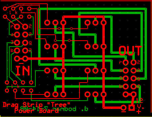
This board will accommodate the 8 power transistors that power the incandescent "Christmas Tree"


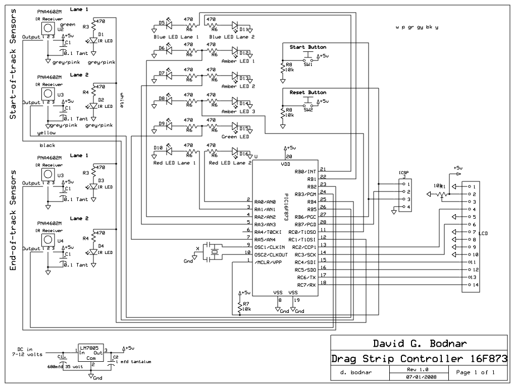
Schematic 16F873a (28 pin PIC)

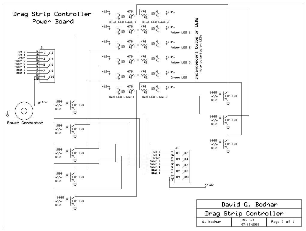
Power Board for Incandescent Lights

Software - PIC 16F873a
'd. bodnar  7-21-08
'revised to add sensor test routines if button pressed during initial screen
'revised to have timing start when start sensor broken - reaction is between
'        green on and break in start sensor
 cmcon=7                 'allows you to use pins as digital rather than analog
 @ DEVICE  PIC16F873A, WDT_OFF, LVP_OFF, PWRT_ON, PROTECT_ON, BOD_ON
DEFINE OSC 4            'seems to work well @ OSC 4
ADCON1 = 7      'use porta as digital     -MAYBE a 6???
DEFINE LCD_DREG     PORTC 'pins 9-12 on PIC with next item set to "4"
DEFINE LCD_DBIT     4       'change to 4 to use top 4 bits (pins 4-7 rather than 0-3)
DEFINE LCD_RSREG    PORTC  
DEFINE LCD_RSBIT    2       'pin 18 on PIC with PORTA set
DEFINE LCD_EREG     PORTC  
DEFINE LCD_EBIT     3      'pin 17 on PIC with PORTA set 

RedLED1             VAR porta.0     'pin 2 
RedLED2             VAR porta.1     'pin 3
AmberLED1           VAR porta.2     'pin 4
AmberLED2           VAR porta.3     'pin 5  
AmberLED3           VAR portc.0     'pin 11 
'ResetButton         var porta.5     'pin 4   'ground pin 4 to do a hard reset
GreenLED            VAR porta.5     'pin 7 
'IR_LED              var portb.0     'pin 6   '38 KHz

BlueLED2            VAR portb.0     'pin 21 
BlueLED1            VAR portb.1     'pin 22 
SensorEnd2          VAR portb.2     'pin 23   'end of run lane 1
SensorEnd1          VAR portb.3     'pin 24   'end of run lane 2
SensorStart1        VAR portb.4     'pin 25  'start of run lane 1
SensorStart2        VAR PORTb.5     'pin 26  'start of run lane 2
StartButton         VAR portb.6     'pin 27 
SerialOut           VAR portb.7     'pin 13 

line1               CON 128
line2               CON 192
line3               CON 148
line4               CON 212
TimeAdjust          CON 410

x                   VAR WORD
y                   VAR WORD
temp1               VAR BYTE
temp2               VAR BYTE
temp3               VAR BYTE
temp4               VAR BYTE
seconds             VAR BYTE
tenths              VAR BYTE
hundredths          VAR BYTE
Winner              VAR BYTE        '1 if lane 1, 2 if lane 2
Lane1Reaction       VAR WORD
Lane2Reaction       VAR WORD
Lane1Total          VAR WORD
Lane2Total          VAR WORD
Counter             VAR WORD
StagingLane1Flag    VAR BYTE '0=not staged, 1=staged, 2=if in RED, 3=false start
StagingLane2Flag    VAR BYTE ' "
TestFlag            VAR BIT     'used to flag sensor test during init
VersionWhole        VAR BYTE
VersionDecimal      VAR BYTE
VersionWhole        =   2
VersionDecimal      =   8

TRISA = %00000000   'set pins 0,1,5 as inputs - others as outputs
TRISB = %01111100   'set pins 1,2,6 as inputs - others as outputs
TRISC = %00000000
HPWM 2,  128,38000     'pin 12  portc.1 'hpwm IR_LED,  127,38000    'may be HPWM 2, ...
test:
TOGGLE portb.7'  DON"T KNOW WHY BUT THIS SETTLES THINGS DOWN!
LCDOUT  $fe,1:PAUSE 100
LCDOUT $fe,line3," (c) d.bodnar 2008"  
LCDOUT  $fe, line2+4,"Version ",#VersionWhole,".",#VersionDecimal' ," OK"
LCDOUT $fe, line4,"TrainElectronics.com"
LCDOUT $fe, line1,"DragStrip Controller"
TestFlag=0
GOSUB allledsoninsequence
 
Initialize:
Winner=0:Lane1Reaction=0:Lane2Reaction=0:Lane1Total=0:Lane2Total=0
StagingLane1Flag=0:StagingLane2Flag=0
Counter=0
GOSUB allledsoff:

IF TestFlag=1 THEN GOSUB TestSensors

FOR x= 1 TO 3
    HIGH Blueled1:HIGH blueled2
    FOR y= 1 TO 50    
        GOSUB CheckButton
        PAUSE 5
    NEXT y
    LOW BlueLED1 :LOW blueled2
    FOR y= 1 TO 30    
        GOSUB CheckButton
        PAUSE 5
    NEXT y
NEXT x

LCDOUT $fe,1,"Press START"
LCDOUT $fe,line2,"To Begin Staging"

Staging0
IF startbutton=0 THEN staging0:

Staging:
LCDOUT $fe,1,line1,"STAGING"
LCDOUT $fe,line2,"Please move engines"
LCDOUT $fe,line3,"to line then back"
LCDOUT $fe,line4,"Lane1 NO  Lane2 NO"
Staging2:
'wait till each lane goes red then backs off so red LED is off 
'light blue LEDs & top amber LEDs to indicate staging not done
'turn each blue LED off as lane is staged
'turn amber1 off when both staged
'continue to look for crossing sensor early
IF sensorstart1=1 THEN  'must hit sensor then back off
    StagingLane1Flag=2  'shows that sensor was hit once
   HIGH redled1
    LCDOUT $fe,line4+6,"NO2 "
ENDIF
IF sensorstart1=0 AND StagingLane1Flag=2 THEN
    StagingLane1Flag=1  'set flag = 1 if sensor hit then backed off
    LOW redled1
    LCDOUT $fe,line4+6,"OK  "
ENDIF
IF sensorstart2=1 THEN
    StagingLane2Flag=2
    HIGH redled2
    LCDOUT $fe,line4+16,"NO2 "
ENDIF
IF sensorstart2=0 AND StagingLane2Flag=2 THEN
    StagingLane2Flag=1
    LOW redled2
    LCDOUT $fe,line4+16,"OK  "
ENDIF
IF StagingLane1Flag<>1 THEN 
      HIGH BlueLED1
    ELSE
     LOW BlueLED1
ENDIF
IF StagingLane2Flag<>1 THEN 
      HIGH blueled2
    ELSE
      LOW blueled2
ENDIF
IF StagingLane1Flag=1 AND StagingLane2Flag=1 THEN 
    LCDOUT $fe,line1,"PRESS START TO RACE "
    IF startbutton=1 THEN   donestaging:    
ENDIF
GOTO staging2:

DoneStaging:
LCDOUT $fe,1, "  STAGING COMPLETE  "
FOR x=1 TO 3:HIGH blueled1:HIGH blueled2:PAUSE 40:LOW blueled1:LOW blueled2:PAUSE 50:NEXT x
GOSUB allledsoff

StartTreeCountdown:
GOSUB AllLEDsoff:
LCDOUT $fe,1,"Ready!"
HIGH AmberlED1:GOSUB CheckForFalseStart:LOW amberled1
LCDOUT $fe,line2,"On Your Mark!"
HIGH amberled2:GOSUB CheckForFalseStart:LOW amberled2
LCDOUT $fe,line3,"Get Set!"
HIGH amberled3:GOSUB CheckForFalseStart:LOW amberled3
LCDOUT $fe,1,"GO!"
HIGH greenled:

'about 4100 counts for 10 seconds - max is about 150 seconds with "pause 2"
Timing:
Counter=Counter+1
PAUSE 2
IF sensorstart1=1 AND Lane1Reaction=0 THEN 
    Lane1Reaction=Counter
    seconds=Lane1Reaction/TimeAdjust
    tenths=Lane1Reaction-(seconds/TimeAdjust)
    LCDOUT $fe,line1,"Lane 1 ",#seconds,".",#tenths
ENDIF
IF sensorstart2=1 AND Lane2Reaction=0 THEN 
    Lane2Reaction=Counter
    seconds=Lane2Reaction/TimeAdjust
    tenths=Lane2Reaction-(seconds/TimeAdjust)
    LCDOUT $fe,line2,"Lane 2 ",#seconds,".",#tenths
ENDIF

IF sensorend1=1 AND Lane1Total=0 THEN 
    Lane1Total=Counter - Lane1Reaction
    IF Lane2Total=0 THEN HIGH blueled1
    seconds=Lane1Total/TimeAdjust
    tenths=Lane1Total-(seconds*TimeAdjust)
    LCDOUT $fe,line1+14,#seconds,".",#tenths
ENDIF
IF sensorend2=1 AND Lane2Total=0 THEN 
    Lane2Total=Counter - Lane2Reaction
    IF Lane1Total=0 THEN HIGH blueled2
    seconds=Lane2Total/TimeAdjust
    tenths=Lane2Total-(seconds*TimeAdjust)
    LCDOUT $fe,line2+14,#seconds,".",#tenths    
ENDIF
IF Lane1Total=0 OR Lane2Total=0 THEN GOTO timing

ReportResults:
LOW greenled
IF Lane1Total< Lane2Total THEN
      LCDOUT $fe,line3, "LANE 1 WINS!"
      HIGH blueled1
    ELSE
      LCDOUT $fe,line3,"LANE 2 WINS!"
      HIGH blueled2
ENDIF
LCDOUT $fe,line4, "RESET to RESTART"

END

CheckForFalseStart:
FOR x=1 TO 15000  'adjust this for approx 1/2 second
    IF sensorstart1=1 THEN 
        StagingLane1Flag=3   'false start
        HIGH redled1
    ENDIF
    IF sensorstart2=1 THEN 
        StagingLane2Flag=3   'false start
        HIGH redled2
    ENDIF
NEXT x
RETURN

AllLEDsOff:
LOW blueled1:LOW blueled2:LOW amberled1:LOW amberled2:LOW amberled3:
LOW greenled:LOW redled1:LOW redled2
RETURN
AllLEDsOn:
HIGH blueled1:HIGH blueled2:HIGH amberled1:HIGH amberled2:HIGH amberled3
HIGH greenled:HIGH redled1:HIGH redled2
RETURN

AllLEDsOnInSequence:
TestFlag=0
HIGH blueled1:PAUSE 100:LOW blueled1
GOSUB CheckButton
HIGH blueled2:PAUSE 100:LOW blueled2
GOSUB CheckButton
HIGH amberled1:PAUSE 100:LOW amberled1
GOSUB CheckButton
HIGH amberled2:PAUSE 100:LOW amberled2
GOSUB CheckButton
HIGH amberled3:PAUSE 100:LOW amberled3
GOSUB CheckButton
HIGH greenled:PAUSE 100:LOW greenled
GOSUB CheckButton
HIGH redled1:PAUSE 100:LOW redled1
GOSUB CheckButton
HIGH redled2:PAUSE 100:LOW redled2
GOSUB CheckButton
RETURN

CheckButton:
IF Startbutton =1 THEN GOTO TestSensors
RETURN

TestSensors:
temp1=0:temp2=0:temp3=0:temp4=0
LCDOUT $fe,1,"    SENSOR TEST"
LCDOUT $fe,line2,"START 1/2  END 1/2"
LCDOUT $fe,line4," Hit RESET when done"
Loop0
IF sensorstart1=1 THEN temp1=temp1+1
IF sensorstart2=1 THEN temp2=temp2+1
IF sensorend1=1 THEN temp3=temp3+1
IF sensorend2=1 THEN temp4=temp4+1
LCDOUT $fe,line3,"   ",#temp1," / ",#temp2,"   ",#temp3," / ",#temp4," "
GOTO loop0

Marlin P. Jones Power Supply

I needed two identical power supplies for testing the drag strip so I ordered two of these:

http://www.mpja.com/prodinfo.asp?number=16854+PS

from Marlin P. Jones in Florida.  For the price ($14.95 + shipping) they can't be beat!

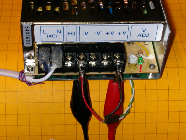
The terminals to the left connect to 110 volts.  Once connected the screw terminals are "hot" so I thoroughly covered them and any exposed wire with a large helping of hot melt glue.  I also added a wire strain relief which you can see to the left.  The line input from the 110 volt cord (the black wire) goes to the "L" terminal and the neutral (white wire) goes to the "N" terminal.  If you use a grounded plug the ground wire (green) goes to "FG".

The two "-V" terminals are the negative DC output while the two "+V" terminals are positive.  The voltage can be adjusted between 20 and 29 volts by turning the small white potentiometer under the "V ADJ" label.  It is glued in place so a bit of effort may be needed to change its setting.

Ultimately this power supply will be placed into another enclosure so that there will be no chance of anyone coming into contact with the AC line input voltage.