Click here for Arduino (ATTiny85) version
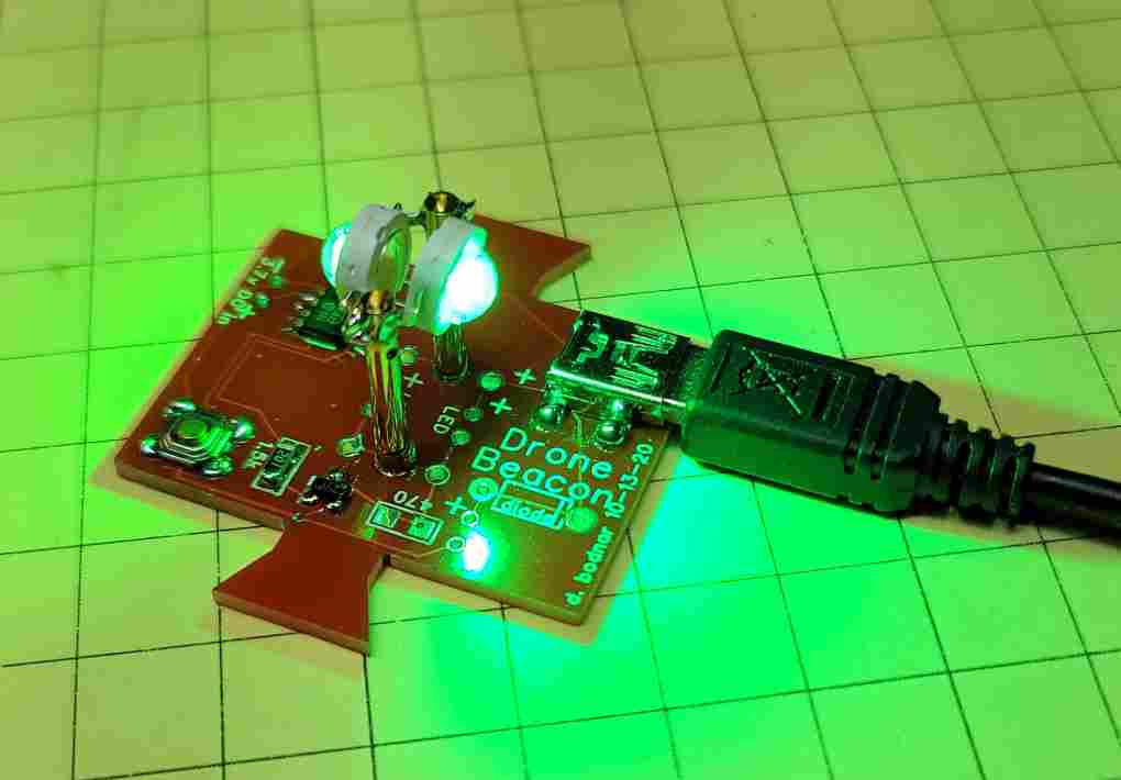
| Recently I have been enjoying flying drones and exploring the photographic opportunities that they provide. My DJI Mavic Mini is a super little drone but its small size and light grey paint scheme can make it hard to follow once it is 100 feet or more away. The built-in green LED that flashes on the back of the drone does little to help with this situation so I decided to add a bright, blinking LED beacon to the bottom of the drone. Initially I repurposed a circuit board from my Bike Blinker Plus. While it worked well it was not ideal as I had to do some modifications to it. A custom Drone Blinker circuit board was designed and fabricated. It is shown here.
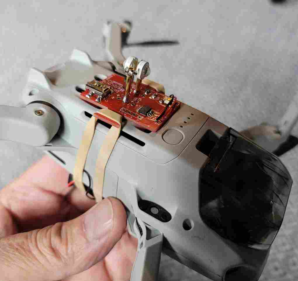
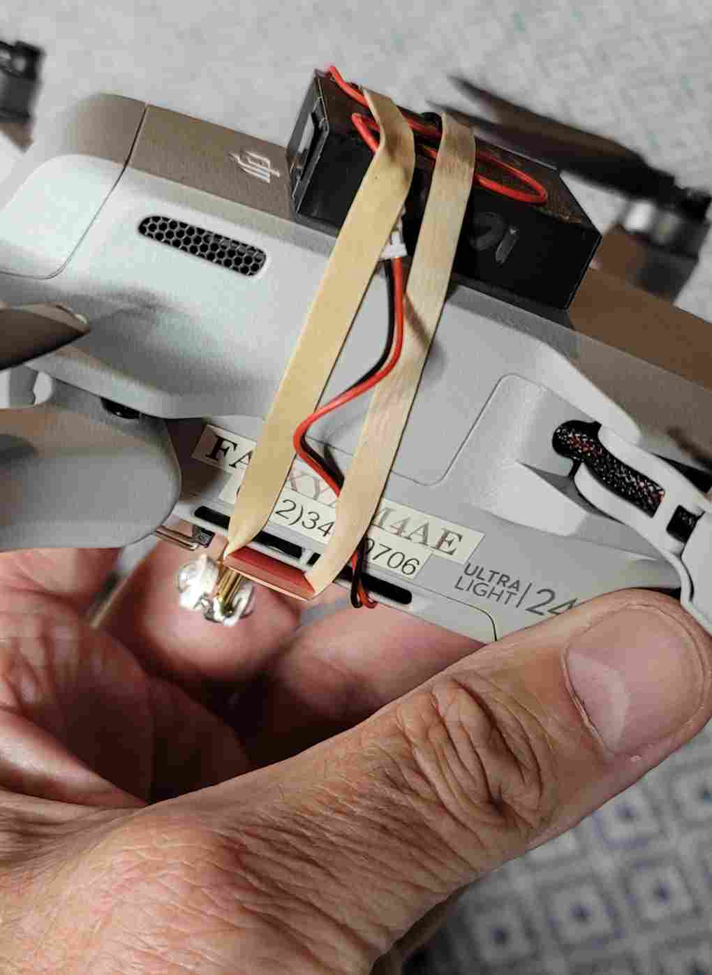
The two tabs at top and bottom are used with a rubber band to hold the blinker & battery to the drone. Make sure the blinker does not block or cover any of the drone's sensors.
|
| The Circuit The circuit is composed of a PIC processor (12F683), an N-channel Mosfet, a pushbutton switch and a resistor. The PIC was chosen due to its small size, low price and low current draw when put to "sleep".
|
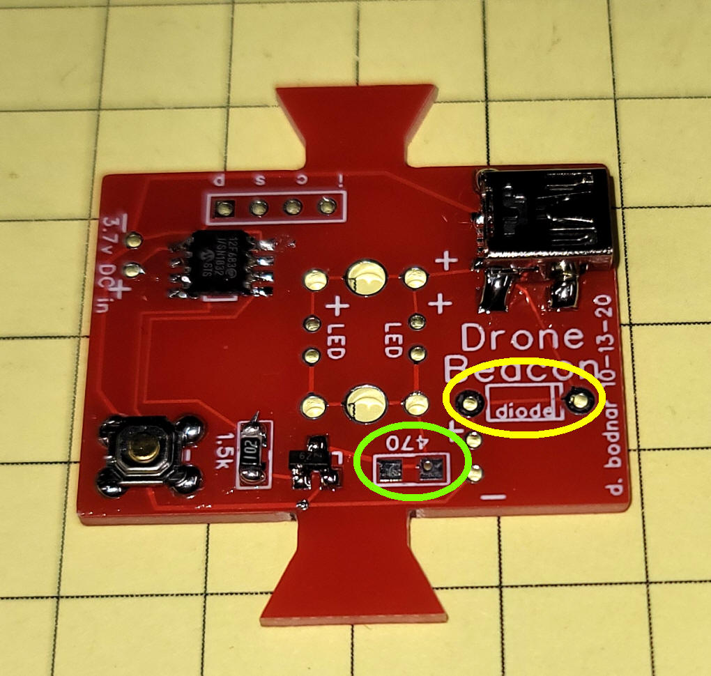
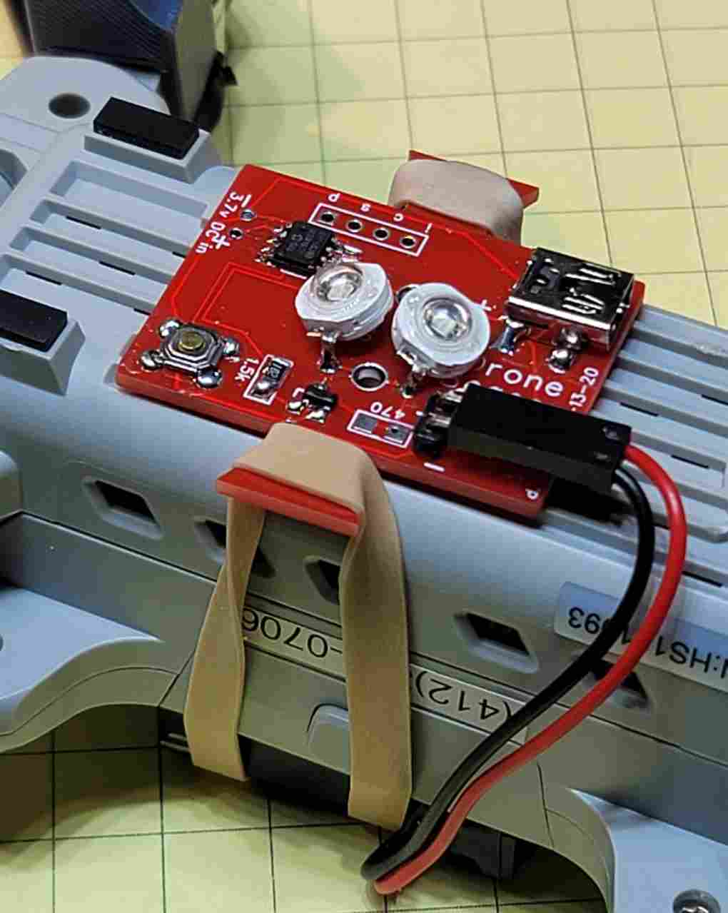
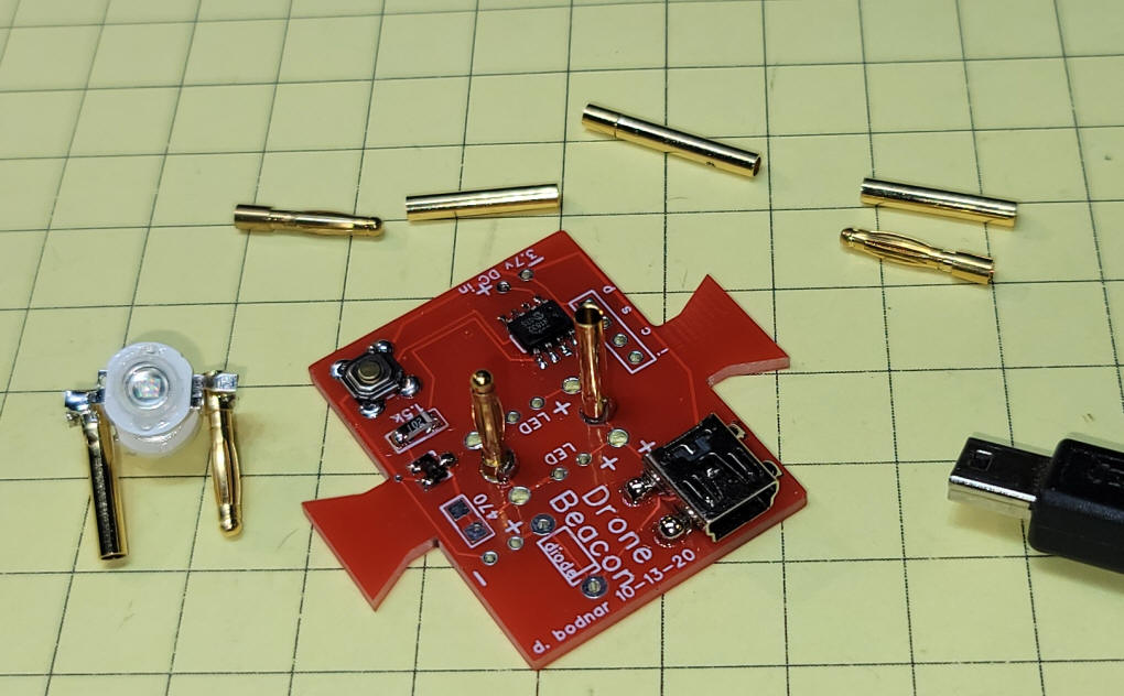
| The Circuit Board Parts placement is shown here. The microcontroller (12F683) is in the upper left, the push button switch is in the lower left and the Mosfet and associated resistor are just to the switch's right. In the upper right there is a mini USB socket that can be used to charge the battery. An optional current limiting resistor can be added in the area circled in green, If you look closely you will see a small trace that shorts out that component so that trace must be cut in order to use the resistor. Similarly there is an optional diode circled in yellow. It can be used to protect from reversing battery polarity. It also is jumpered. I found that adding the diode did work but it dropped the voltage going to the LED by 0,7 volts noticeably dimming it so I chose not to use it.
|
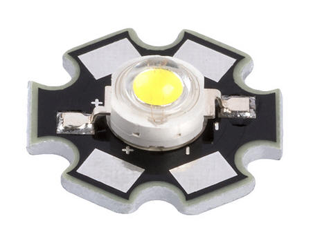
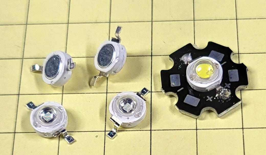
| LED Options There are several things to consider when choosing the LED or LEDs that you use on the beacon. Initially I used a 3 watt bright white LED. It worked well but was not as noticeable on the drone as I had hoped it would be. That led me to experimenting with LEDs of various colors. After testing Red, Blue and Green I found that my eyes saw the green LED the best. A little research found that yellow and green are seen best by the human eye, confirming my observations. The other consideration is the LED package. Most high output LEDs come attached to a star shaped metal heat sink like the one shown here.
For most of the beacons I have tested I used the same LED but without the heat sink, This allows the beacon to be smaller than when the LED is mounted vertically. Since the LEDs are on for less than half the time they don't overheat without the heat sink. If they were on continuously I would surely use the ones with the heat sink.
|
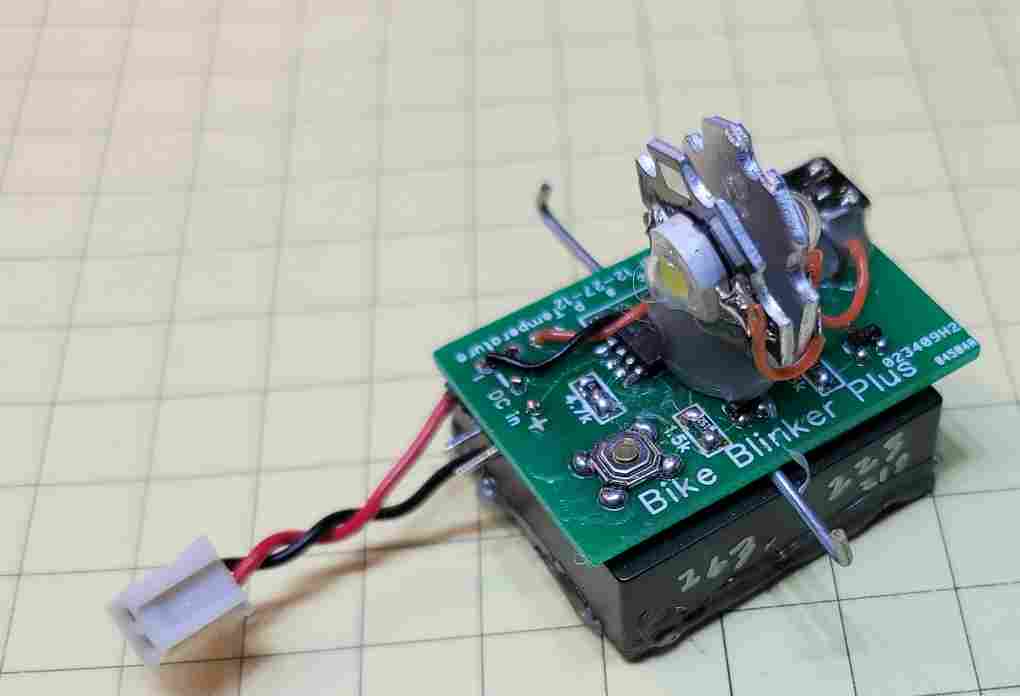
| LED Mounting Options The smaller footprint LEDs (those without the heat sink) give the most options for mounting. This prototype (built on the board for the bike helmet blinker) shows two LEDs with heat sinks mounted vertically.
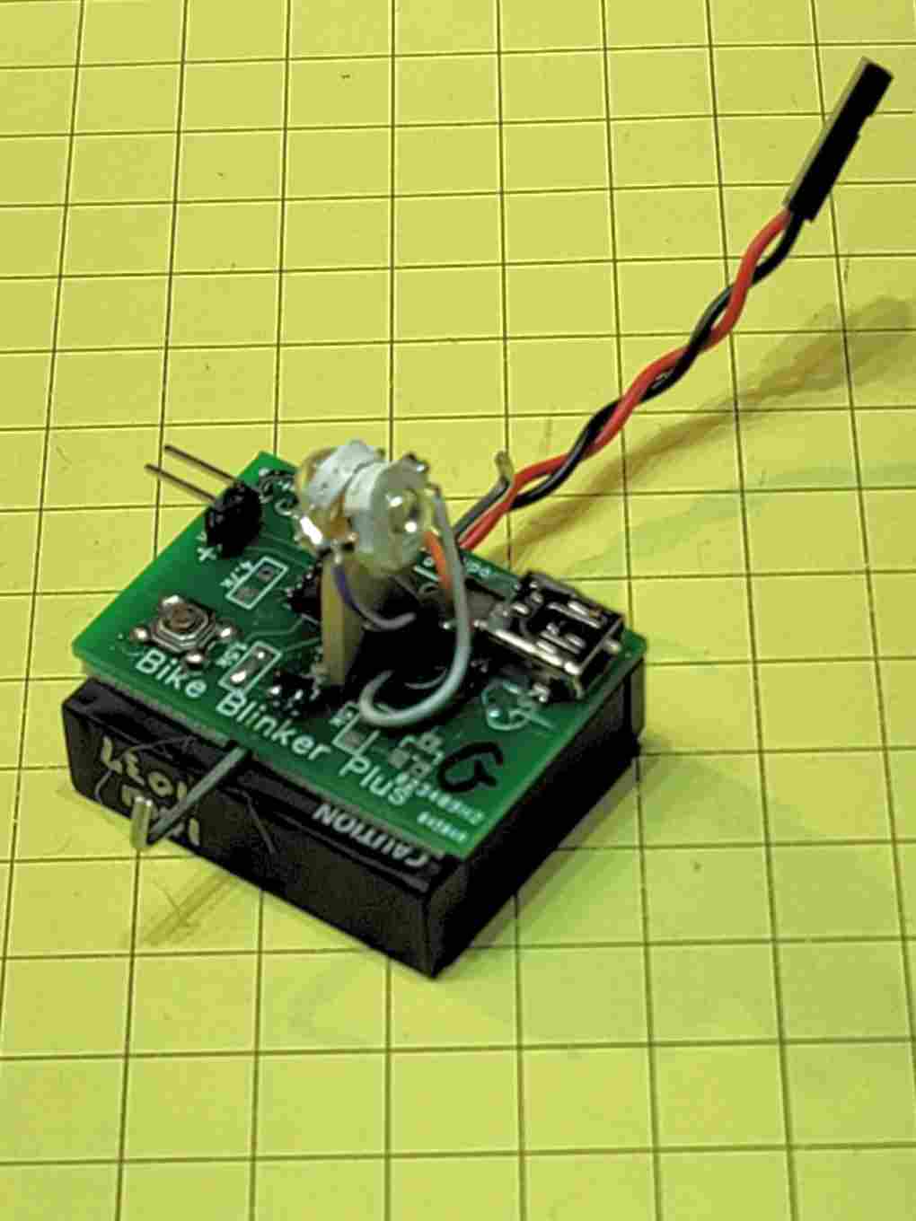
Here is another prototype with two bare LEDs mounted about 3/4" above the circuit board.
The newest board allows more flexibility in mounting LEDs. Here two bare LEDs are mounted low on the board and slightly angled down & to the side.
The latest board has two larger holes to accept 2mm brass bullet connectors as shown here, They raise the LEDs about 3/4" above the board.
The connectors are shown here. Note that there is a male and female part to the connector.
|
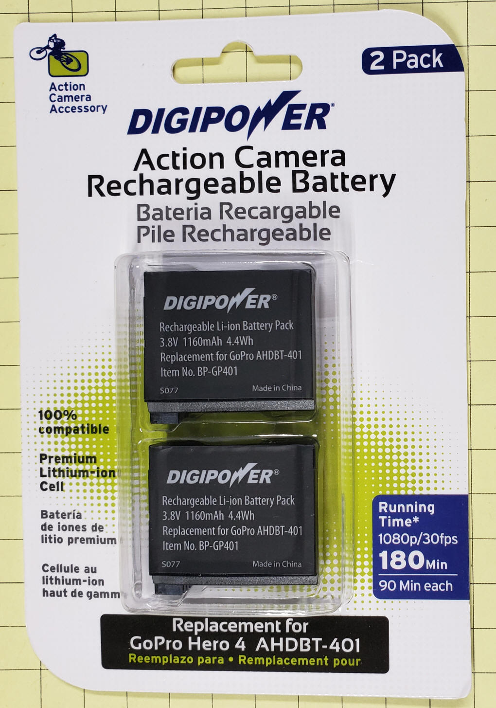
| Battery Options Any Lithium Ion cell or battery that supplies 3.5 to 4 volts should work well. The board is sized so that it fits nicely on a GoPro Hero 4 battery that I got on eBay. These are New-Old-Stock batteries. While they may not be capable of supplying their original power output they can supply more than enough current to run the Drone Beacon for hours. Another important consideration for any Lithium Ion battery you choose is that it contains an internal management circuit that protects it from over voltage and under voltage. These batteries do have that capability, as do most cell phone & camera batteries.
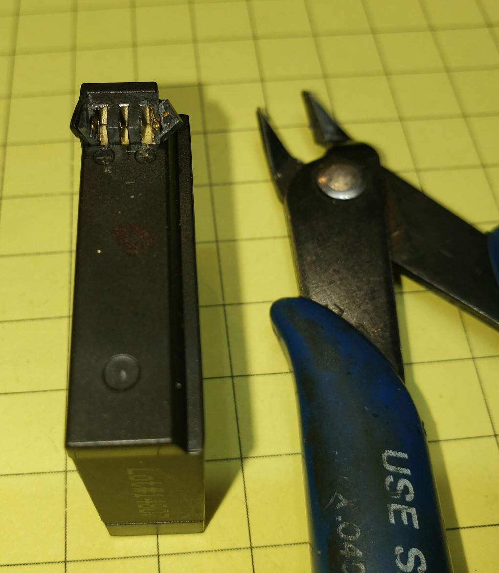
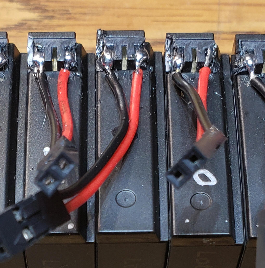
To connect to its terminals I trimmed away some of the plastic that surrounds the terminals and soldered wired (red and black for positive and negative respectively) directly to the gold terminals. The positive terminal is on the left and negative terminal is on the right as marked on the case.
Here you can see the power wires soldered to several of the batteries before I insulated the connections with hot melt glue.
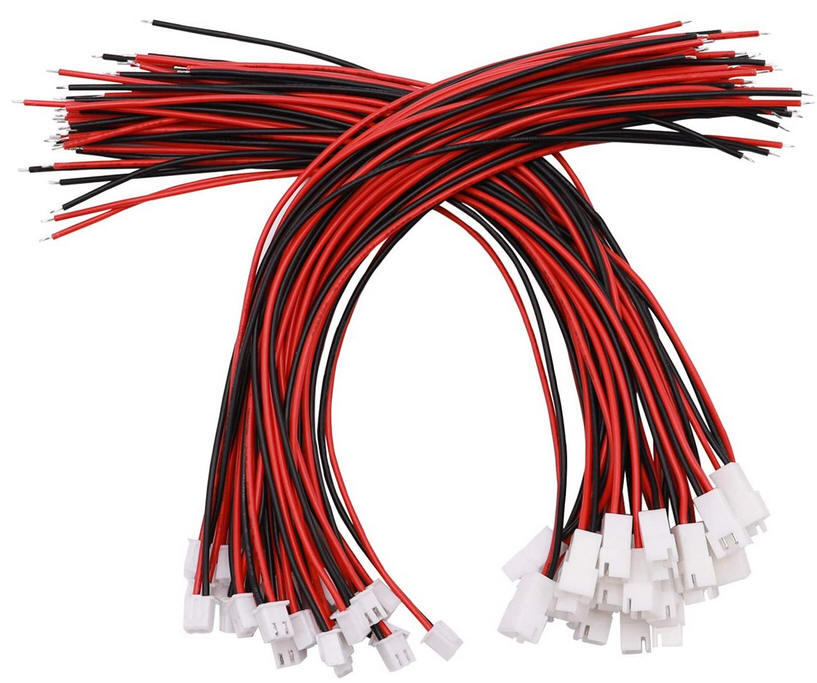
The batteries shown here use a simple 2 pin Dupont connector that plugs into a pair of pins on the board. This setup works well but does run the risk of reversing the plug and destroying the microprocessor. Another safer option is to use polarized plugs like these - their longer length also gives the option of mounting the battery on the top and the circuit board on the bottom of the drone.
|
| Mounting on the Drone The beacon can be placed either on the top or bottom of the drone. It is important that no part of the beacon block sensors on the drone. You either mount the board and the battery together or put one part on the top and the other part on the bottom. All you need is to run the power wires between them. (see connectors above)
|
| Modes The button on the circuit board is used to switch modes and to turn the unit off and on. The board is programmed to display 5 different blinking modes
To change mode press the switch - while it is held down the LED will flash a number of times that represents the mode you will enter when you release the button. For example, if you are currently in mode 2 and you hold the button down the LED will flash 3 times, pause, flash 3 times and so on. This flashing of the new mode number only repeats 5 times - if you hold it so that the mode blinks 5 times the LED will dim till off and the unit will be in sleep mode until the button is pressed again. When the unit is put to sleep the microcontroller still draws a small amount of current from the battery. I measured the current consumption at 0.055 ma. If the battery is good for 1000 ma hours theoretically the sleep mode could last for nearly two years.
|
| Charging The battery can be charged by connecting a mini-USB cable to the receptacle on the board. |
CodeThe code below is version 12f683_LED_Bike_Blinker-DRONE-Button4ModesV1-4_.bas It is based on the Bike Blinker code and may contain some items from it that are not used with the drone beacon '''Modified for Drone using modes button as per Bike Blinker Plus 10-22-2020
''' SOLID ON removed 10-19-2020
Include "modedefs.bas"
ansel=0 'use pins as digital rather than analog
option_reg.7=0 'turn on weak pull ups
wpu = %00100000 'weak pull ups on pin GPIO.5 only
INTCON = %00001100 '00xx11xx to be CCP1 mode
SerialOut var GPIO.0 'pin 7
NotUsed1 var GPIO.1 'pin 6
LED var GPIO.2 'pin 5
NotUsed3 var GPIO.3 'pin 4
ChangeSwitch var GPIO.5 'pin 2
Mode var byte 'branch variable
Y var byte 'for/next variable
SleepCounter Var byte 'count times mode shown before sleep
TPause con 300
BetweenPause con 300
Mode = 1 'start in Temperature reporting mode
GPIO = %00110000 'GPIO 4 & 5 as inputs - others as outputs
data @0,1,1 'start with Fahrenheit scale when programmed
read 1, mode 'read mode
serout serialout,t9600,[12,10,13,"Ver 1.4 DRONE Blinker ",10,13]
serout serialout,t9600,["(c) d. bodnar 10-22-20",10,13]
start:
if changeswitch=0 then goto ChangeMode
Branch Mode, [FirstRoutine, FirstRoutine, FullBrightFast, FullBrightSlow, FullOn, Another]
goto start:
Another:
if changeswitch=0 then goto ChangeMode 'watch for button press
high led
pause 50
low led
pause 450
goto start:
FirstRoutine:
high LED:for y=1 to 20:toggle led:pause 20:next Y:low led 'fast blink @ start
if changeswitch=0 then goto ChangeMode 'watch for button press
pause 400
goto start
FullBrightFast: 'full brightness - fast blink
serout serialout,t9600,["@f",10,13]
high led:pause 60:low led:pause 60:Goto start:
FullBrightSlow: 'full brightness - slow blink
serout serialout,t9600,["@s",10,13]
high led:pause 500:low led:pause 500:Goto Start:
FullOn:
serout 0,t9600,[10,13,"@ON",10,13]
if changeswitch=0 then goto ChangeMode 'watch for button press
high LED:for y=1 to 10:toggle led:pause 10:next Y:low led 'fast blink @ start
pause 50
if changeswitch=0 then goto ChangeMode 'watch for button press
high LED:for y=1 to 10:toggle led:pause 10:next Y:low led 'fast blink @ start
pause 50
if changeswitch=0 then goto ChangeMode 'watch for button press
high LED:for y=1 to 10:toggle led:pause 10:next Y:low led 'fast blink @ start
pause 50
if changeswitch=0 then goto ChangeMode 'watch for button press
high LED:for y=1 to 30:toggle led:pause 30:next Y:low led 'fast blink @ start
if changeswitch=0 then goto ChangeMode 'watch for button press
pause 250
if changeswitch=0 then goto ChangeMode 'watch for button press
goto start:
Changemode:
sleepcounter=0
serout serialout,t9600,["CMd",10,13]
low led
Mode=Mode+1:if Mode>5 then mode=1
StayHere:
sleepcounter=sleepcounter+1
if sleepcounter >=6 then GoToSleep 'if held for 5 repeats goes to sleep
for y=1 to Mode:high led:pause 100:low led:pause 100:next y:pause 500 'flash mode
if changeswitch=0 then StayHere: 'stay put till button released
serout serialout,t9600,["MD=",#mode,10,13]
pause 300
write 1,mode 'save current mode
goto start:
MinPWM:
for y= 255 to 0 step -1
pwm 2, y, 3
if changeswitch=0 then goto ChangeMode
next y
return
MaxPWM:
for y= 0 to 255
pwm 2, y, 3
if changeswitch=0 then goto ChangeMode
next y
return
GoToSleep:
mode=mode-1
write 1, mode 'save current mode
serout 0,t9600,[10,13,"@Sleep",10,13]
for y= 255 to 0 step -1 'dim showing going to sleep
pwm 2, y,3
next y
low led:
INTCON.0 = 0 'Reset the Port change bit
IOC=0
LongSleep:
serout 0, t9600, ["Z", 10,13]
Pause 3000
INTCON.0 = 0 'Reset the Port change bit
gpio.5=0 'reset switch pin
IOC = %00100000 'enable INTERRUPT ON CHANGE on gpio 5
sleep 65000
if intcon.0=0 then goto longsleep
INTCON.0 = 0 'Reset the Port change bit
IOC=0
for y= 0 to 255 'brighten LED to show waking up
pwm 2, y,3
next y
serout 0, t9600, ["xZ", 10,13]
INTCON.0 = 0 'Reset the Port change bit
pause 1000
goto start:
|
| Other Applications This simple circuit does a great job making the drones more visible. It is also useful wherever you need to draw attention to someone or something. If you replaced the LEDs with RED ones it would be ideal for the rear of a bicycle. With white LEDs it would be great on the front of a bike.
|