| I have enjoyed programming various Arduino
microcontrollers over the last few years. They work well, are
inexpensive and have an extensive support network on the Internet. The only problem that I find is that even the smallest Arduino is much larger than many of the PIC chips that I also use. If space is an issue I usually go for the PIC family of microprocessors. Recently I was working on a project where I wanted to make a small circuit to flash a bright LED beacon to help follow a drone in flight. I designed and built the circuit using a small, surface mount 8 pin PIC chip and wondered if I could make an equally small circuit using an Arduino. A few years ago I had experimented with an 8 pin ATTiny85 chip that could be programmed using the Arduino IDE (programming environment). I decided to revisit that chip and to see if I could translate the program that I wrote in PIC BASIC PRO to the Arduino compiler's "C" so that I could use it with the ATTiny85. I also discovered that there is a surface mount version of the ATTiny85 that had the potential to give me a circuit that was as small as the PIC based unit.
|
| The Circuit The schematic is very similar to the one from the PIC 12F683. The main difference is to the programming wiring to the header labeled "programming". There is also a connection to pin 3 (PB4) that can be used to see the serial output as the unit blinks or progresses from one mode to another.
|
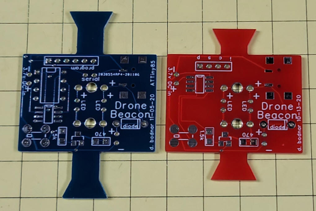
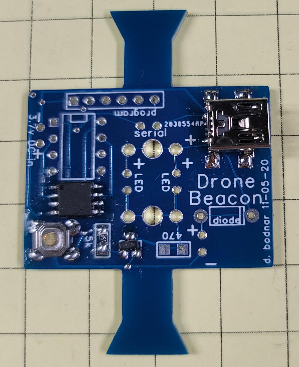
| The Circuit Board The two boards are shown here. The PIC version is on the right in red and the ATTiny85 version is on the left in blue. The most dramatic difference is that the ATTiny85 version has board space for either a through hole processor or a surface mount processor. Just be sure not to install both! The programming header (labeled "program") on the blue board has six pins while the one for the PIC processor only has 4 (labeled "I C S P ).
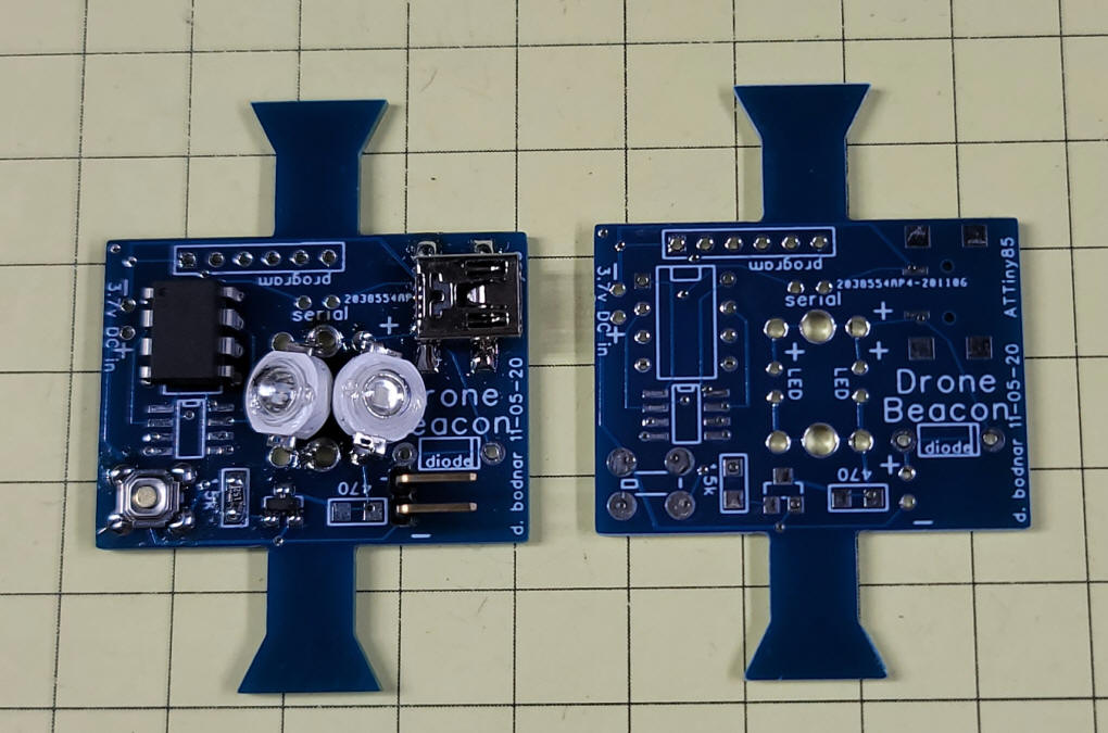
Here the board has been populated with a through hole ATTiny85 (upper left), the USB connector (upper right), button (lower left), Mosfet & resistor (to the right of the switch) and two 3 watt LEDs (center) - there is also a two pin header where the battery can be plugged it (lower right)
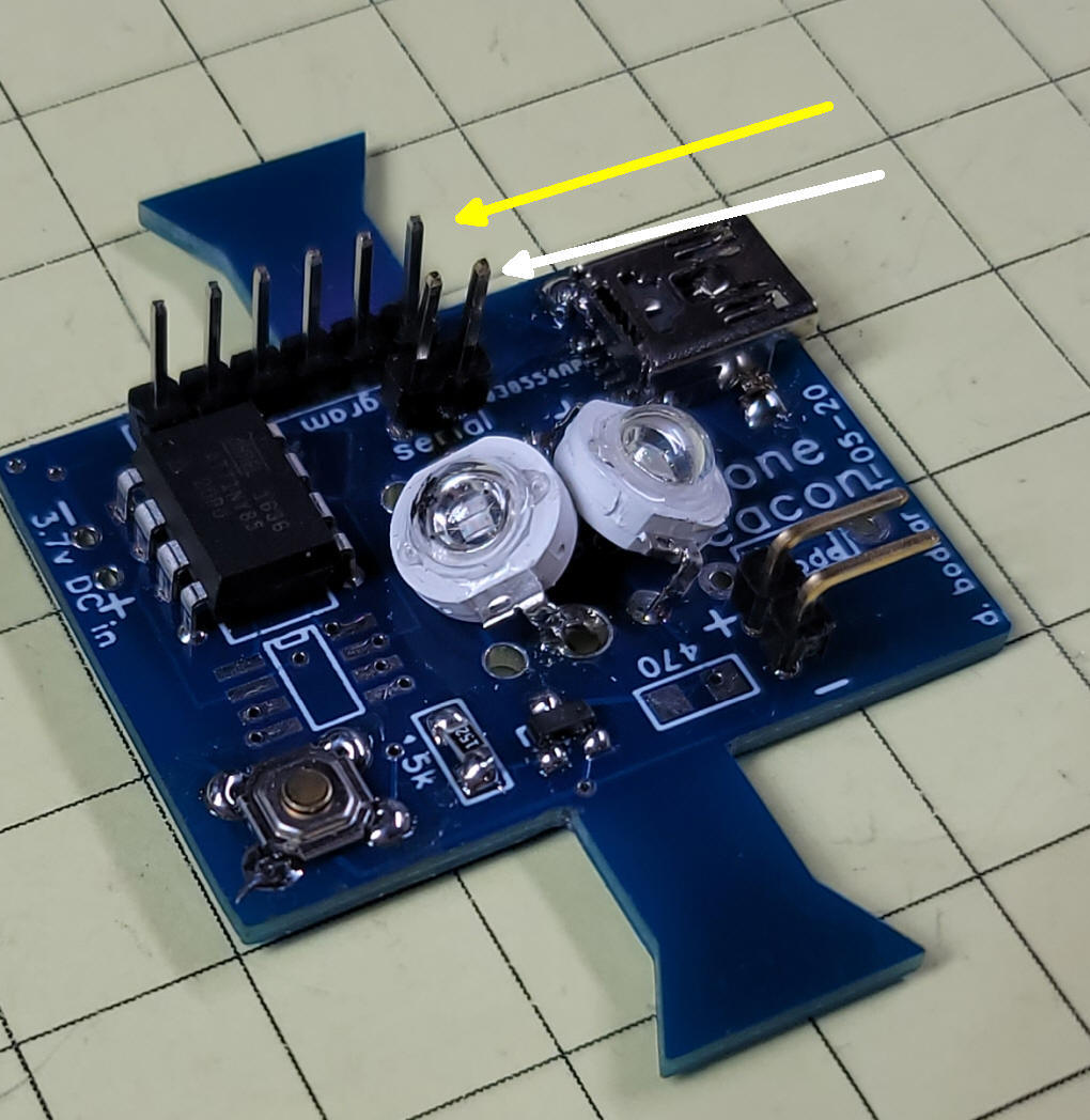
The surface mount version of the ATTiny85 is shown here.
|
| Two headers are at the top of the board.
The six pin header (yellow arrow) is used for programming and the
two pin header (white arrow) can be used to monitor the serial
output from the processor. The pin on the left is the serial
output and the one on the right is ground.
|
| LED Options There are a number of options for LEDs. They have been explored in the earlier web page and can be seen here: http://www.trainelectronics.com/Drone/Beacon/#LED_Options Most of my test beacons have been wired with 3 watt blue & green LEDs as shown in the image above. |
| Battery Options The battery options were also discussed in the earlier web page here: http://www.trainelectronics.com/Drone/Beacon/#battery |
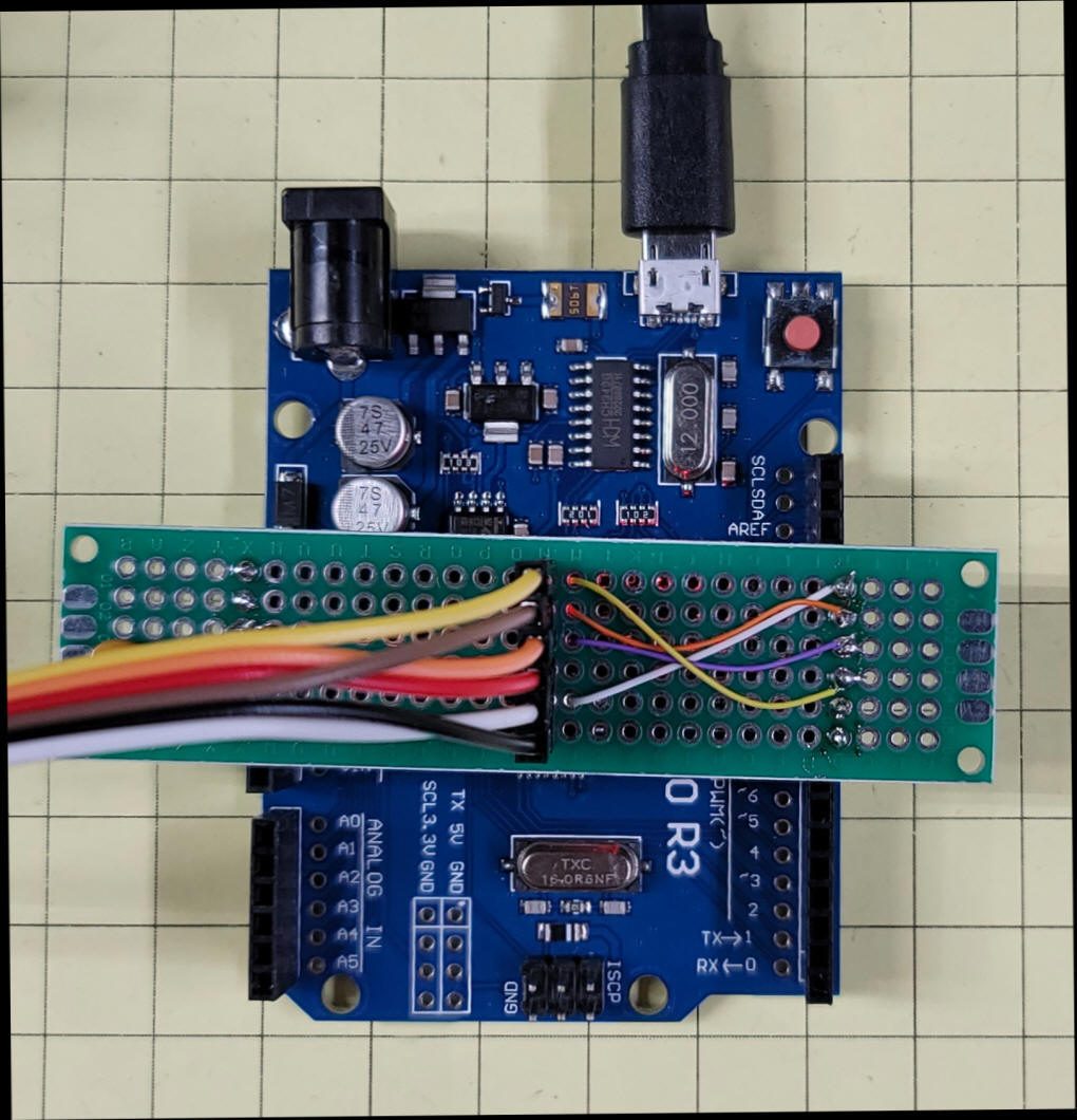
| ATTiny85 Programmer I built a simple programmer for the ATTiny that utilizes an Arduino UNO, Detailed instructions on building this programmer are here: http://www.trainelectronics.com/Drone/ATTinyBeacon/ATTinyProgrammerExample.htm |
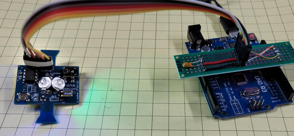
| Simple Programmer Interface To simplify programming the Drone Beacon I set up the Arduino UNO programmer so that its six pin header (shown below) would plug right into the Drone Beacon board. Its wiring and construction are shown here: http://www.trainelectronics.com/Drone/ATTinyBeacon/ATTinyProgrammerExample.htm
|
| Modes The button on the circuit board is used to switch modes and to turn the unit off and on. The board is programmed to display 5 different blinking modes
To change mode press the switch - while it is held down the LED will flash a number of times that represents the mode you will enter when you release the button. For example, if you are currently in mode 2 and you hold the button down the LED will flash 3 times, pause, flash 3 times and so on. This flashing of the new mode number only repeats 5 times - if you hold it so that the mode blinks 5 times the LED will dim till off and the unit will be in sleep mode until the button is pressed again. When the unit is put to sleep the microcontroller still draws a small amount of current from the battery. I measured the current consumption at 0.055 ma. If the battery is good for 1000 ma hours theoretically the sleep mode could last for nearly two years.
|
| ATTiny85 Code The program that was translated from the PIC Basic Pro code is shown below. These three libraries are used in the sketch. I did NOT need to manually add them to my system.
|
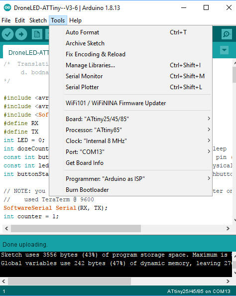
| IMPORTANT - Burn Bootloader First Before you program the ATTiny85 make sure you click on "Burn Bootloader", the last option in the screen shown here. Once that is done you can program the ATTiny85.
|
/*  Translation of Drone Beacon from PIC to Arduino
     d. bodnar  11-12-2020
*/
#include <avr/sleep.h>
#include <avr/interrupt.h>
#include <SoftwareSerial.h>
#define RX    3   // *** D3, Pin 2
#define TX    4   // *** D4, Pin 3
int LED = 0;
int dozeCounter = 0;  // hold button for 5 repeats goes to sleep
const int buttonPin = 3;     // the number of the pushbutton pin (physical pin 2)
const int ledPin =  0;      // the number of the LED pin (physical pin 5)
int buttonState = 0;         // variable for reading the pushbutton status
// NOTE: you have to capture serial output via serial converter on pin 3 on ATTINY - // used TeraTerm @ 9600 SoftwareSerial Serial(RX, TX); int counter = 1; void setup()
{
Serial.begin(9600);
pinMode(LED, OUTPUT);
pinMode(buttonPin, INPUT_PULLUP);
Serial.println("Drone Beacon on ATTiny85--Ver 3.6.");
}
void loop()
{
  dozeCounter = 0;
  Serial.print (" @ LOOP  "); Serial.print(counter); Serial.print(" Button "); Serial.println(buttonState);
  checkButton();
  switch (counter) {
    case 1:
      fullBrightSlow();
      break;
    case 2:
      fullBrightFast();
      break;
    case 3:
      fivePause();
      break;
    case 4:
      threeTen();
      break;
    case 5:
      another();
      break;
  }
}
// 1 1 1
void fivePause() {
  digitalWrite(LED, HIGH);
  for (int i = 1; i <= 5; i++) {
    checkButton();
    digitalWrite(LED, LOW);
    delay(25);
    digitalWrite(LED, HIGH);
    delay(25);
  }
  checkButton();
  delay(250);
}
// 2 2 2
void fullBrightFast() {
  digitalWrite(LED, LOW);
  delay(60);
  checkButton();
  digitalWrite(LED, HIGH);
  delay(60);
}
// 3 3 3
void fullBrightSlow() {
  digitalWrite(LED, LOW);
  checkButton();
  delay(500);
  checkButton();
  digitalWrite(LED, HIGH);
  checkButton();
  delay(500);
  checkButton();
}
// 4 4 4
void threeTen() {
  for (int xx = 1; xx <= 3; xx++) {
    checkButton();
    for (int i = 1; i <= 10; i++) {
      checkButton();
      digitalWrite(LED, LOW);
      delay(10);
      digitalWrite(LED, HIGH);
      delay(10);
    }
    checkButton();
    delay(50);
  }
  for (int i = 1; i <= 10; i++) {
    checkButton();
    digitalWrite(LED, LOW);
    delay(30);
    digitalWrite(LED, HIGH);
    delay(30);
    checkButton();
  }
  delay (250);
}
//5 5 5
void another() {
  digitalWrite(LED, LOW);
  delay(100);
  checkButton();
  digitalWrite(LED, HIGH);
  delay(25);
}
void checkButton() {
  buttonState = digitalRead(buttonPin);
  if (buttonState == HIGH) {
  } else {
    counter = counter + 1;
    if (counter == 6) {
      counter = 1;
    }
  }
  while (digitalRead(buttonPin) == LOW) { // debounce button
    for (int i = 1; i <= counter; i++) {
      digitalWrite(LED, HIGH);
      delay(100);
      digitalWrite(LED, LOW);
      delay (100);
    }
    dozeCounter = dozeCounter + 1;
    Serial.print("dozeCounter ");  Serial.println(dozeCounter);
    if (dozeCounter >= 5) {
      Serial.println(" @ 5 count");
      for (int xx = 255; xx >= 1; xx = xx - 2) {
        analogWrite(LED, xx);
        delay(10);
      }
      delay(1000);
      sleep();
    }
    delay(500);
  }
}
void sleep() {
  counter = counter - 1;
  if (counter == 0) {
    counter = 5;
  }
  Serial.print(counter); Serial.println(" SLEEPING ");
  GIMSK |= _BV(PCIE);                     // Enable Pin Change Interrupts
  PCMSK |= _BV(PCINT3);                   // Use PB3 as interrupt pin
  ADCSRA &= ~_BV(ADEN);                   // ADC off
  set_sleep_mode(SLEEP_MODE_PWR_DOWN);    // replaces above statement
  sleep_enable();                         // Sets the Sleep Enable bit in the MCUCR Register (SE BIT)
  sei();                                  // Enable interrupts
  sleep_cpu();                            // sleep
cli(); // Disable interrupts PCMSK &= ~_BV(PCINT3); // Turn off PB3 as interrupt pin sleep_disable(); // Clear SE bit ADCSRA |= _BV(ADEN); // ADC on sei(); // Enable interrupts
Serial.print(counter); Serial.println(" DONE SLEEPING!!!");
for (int xx = 1; xx <= 255; xx = xx + 2) {
analogWrite(LED, xx);
delay(10);
}
} // sleep
|