|
Introduction For our first round of tests let's start with these assumptions:
White LEDs require at least 3 volts, sometimes more, to fully illuminate. While 3 rechargeable cells (3 x 1.2 volts = 3.6 volts) can work my experiments have found that you can light longer strings of LEDs wired in parallel when using 4 cells (4 x 1.2 volts = 4.8 volts). Four non-rechargeable alkaline cells will work if higher value current limiting resistors are used since 4 alkaline cells = 6 volts, quite a bit more than the 4.8 provided by rechargeables. A 9 volt battery could also be used (with significantly less useful life than the AA and AAA cells) by increasing the value of the current limiting resistor to an even higher value. 5mm warm white LEDs give off light that is much closer to incandescent or other softer white light sources rather than the somewhat glaring blue/white light that is frequently associated with LEDs. They are mounted so that their light shines directly down and will illuminate the coach nicely especially if the interior is painted a light, reflective color. White or off white tissue paper can be mounted over the LEDs to disperse the light more broadly. You can also change the dispersal pattern by drilling the LEDs as described in this article: http://www.trainelectronics.com/Trolley_MrRogers/lights Spacing multiple LEDs close together and lighting the LEDs to less than their maximum brightness gives a better lighting effect than using only a few LEDs at high brightness. While drilling a hole in the bottom of each car and mounting an on/off toggle switch is a good way to turn the power on and off a latching reed switch, mounted to the inside top of the coach roof, can be a better alternative. See: http://www.trainelectronics.com/LED_Articles_2007/LED_103/index.htm These unusual reed switches stay on or off after a magnet is passed over them. |
||||||||||||||||||||||||
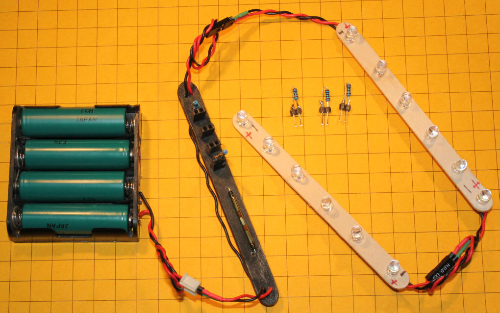
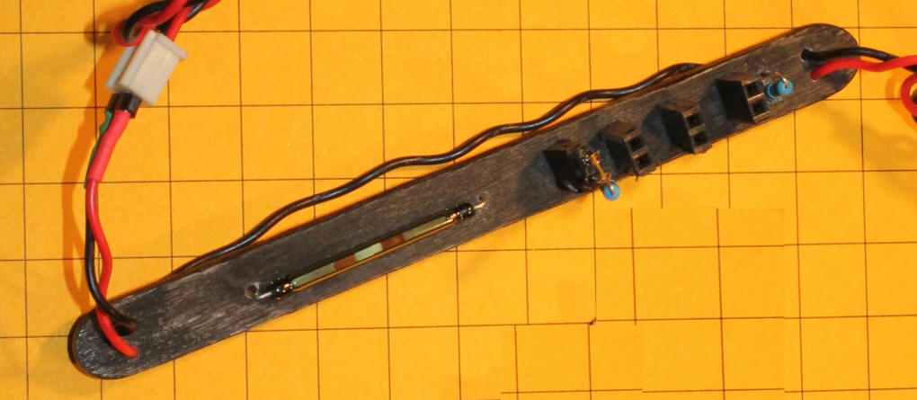
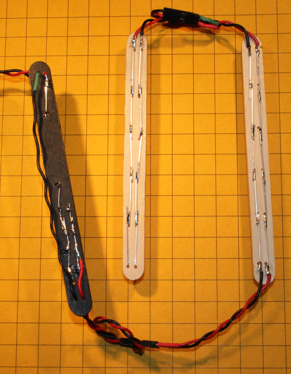
| Test Setup - LED Boards The test LEDs are mounted on popsicle sticks. Circuit boards could, and will, be used but using popsicle sticks is a great alternative when you are experimenting and don't want to wait for circuit boards to be fabricated! Here is the test setup showing two LED boards, a resistor test board (in black) and 4 AA NiMH cells for power. The three striped objects near the center are additional resistors that will be plugged into the sockets on the black popsicle stick to adjust brightness.
To make the LED boards drill six pairs of holes in each stick about 3/4" apart. Each pair of holes for the LEDs should be as far apart as the leads that come out of the bottom of each LED. This is about 1/10 inch.
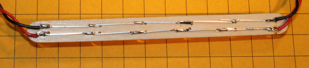
Push the leads through the holes making sure that the LEDs are all aligned with the same orientation, that is with the longer leads (the positive anodes) together on one side and the sorter (negative cathodes) together on the other side. Bend the leads over as shown and solder them together so that the LEDs are wired in parallel. The cathodes (shorter leads) are at the top and wired to the black connecting wire. The anodes (longer leads) are at the bottom and connected to the red connecting wire. Red wire connects the anodes and black the cathodes. Two strips like the one below will give a total of 12 LEDs for testing.
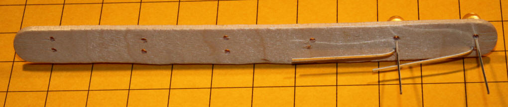
Test Setup - Power Board
The reed switch is to the left with the resistor sockets to the right. The one permanently soldered 100 ohm resistor is at the far right. One plug-in resistor has been inserted in the leftmost socket.
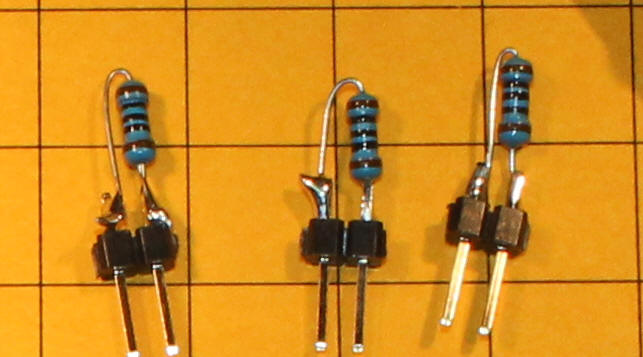
The latching reed switch is fragile and WILL break if you bend its leads without supporting the glass body of the switch. See the information towards the end of this article for tips on safely bending leads: http://www.trainelectronics.com/artcles/SENSORS_partI/index.htm . It explains that you MUST hold each lead close to the glass body of the switch with a pair of pliers as you bend the lead. To make the sockets for the resistors I used sections of plastic headers that can be purchased here: http://www.thaishine.com/servlet/the-790/10-pcs-1x40-Pin/Detail Just cut two pin sections out and mount them as shown. The resistors were soldered to matching headers: http://www.thaishine.com/servlet/the-793/10-pcs.-40-Pin/Detail As shown in the schematic, one 100 ohm resistor was permanently soldered in while the others can be inserted or removed as needed. If you don't want to take the time to deal with sockets and plug in resistors you could just as easily solder in additional resistors as you check LED brightness. Here is a close-up of the resistors.
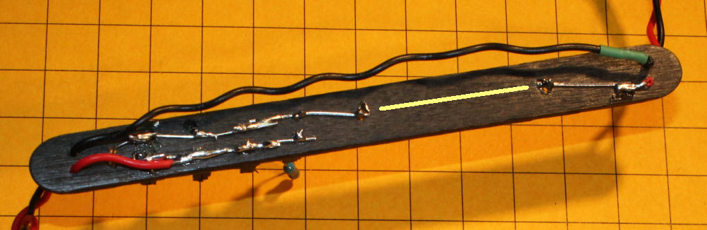
The yellow line indicates where the reed switch is located on the top of the board.
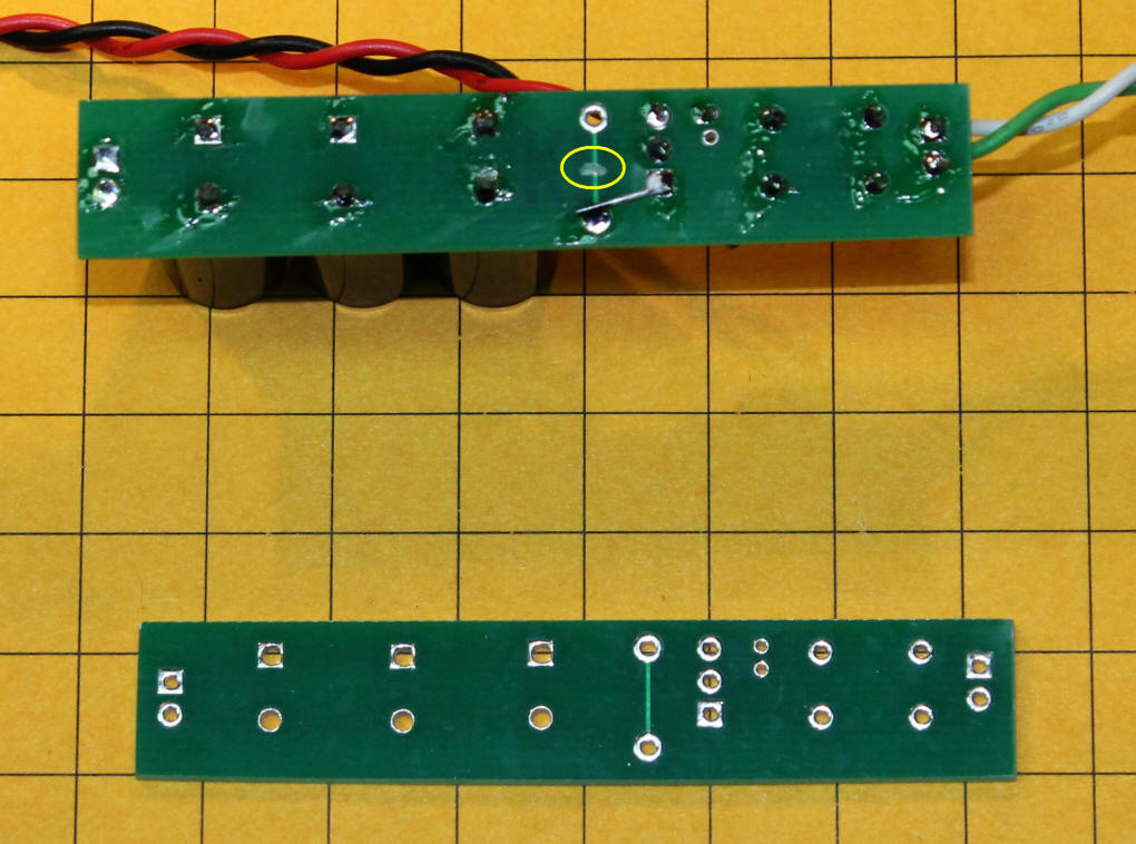
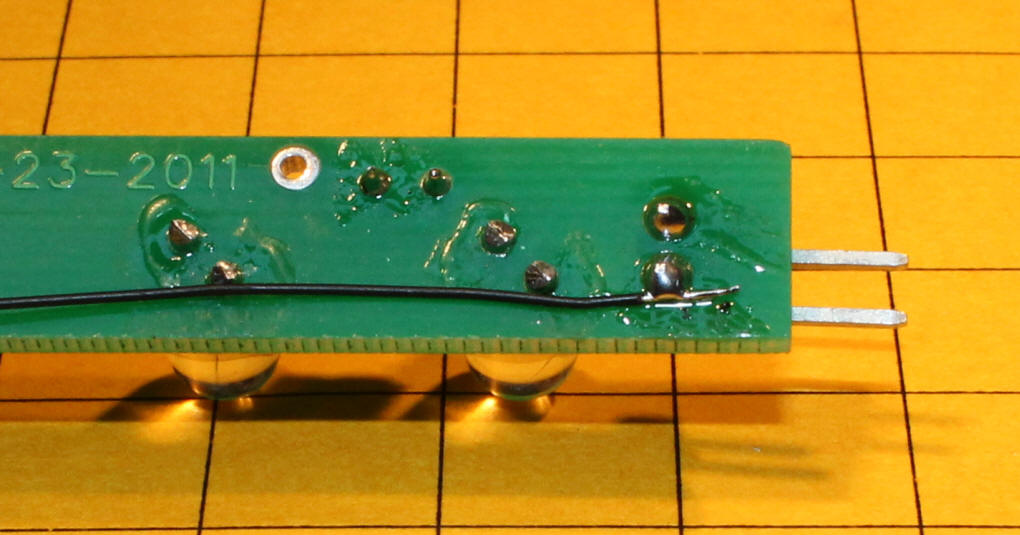
This view of the back of the boards shows all of the wiring.
|
||||||||||||||||||||||||
| Testing Connect the power board to one or more LED strips. You should see each LED light up, but somewhat dimly, when you pass the magnet close to the latching reed switch. If any or all LEDs are not lit check to see that they are all mounted with their anodes together and their cathodes together. You can also put a temporary jumper across the pins of the reed switch to make sure that power is getting through it. Add additional resistors, one at a time, until a good balance between brightness and current consumed is reached. When I used this setup with 12 LEDs the single 100 ohm resistor only allowed a current of 20 ma to flow. The table below shows the power that is provided as more resistors are placed in parallel.
Most nickel metal hydride AA cells deliver 2000-3000 mAh (milliamp hours) of current. AAA cells deliver less than 1/2 as much. As you can see from the table the more current you give the LEDs the less time you get before they go out. |
||||||||||||||||||||||||
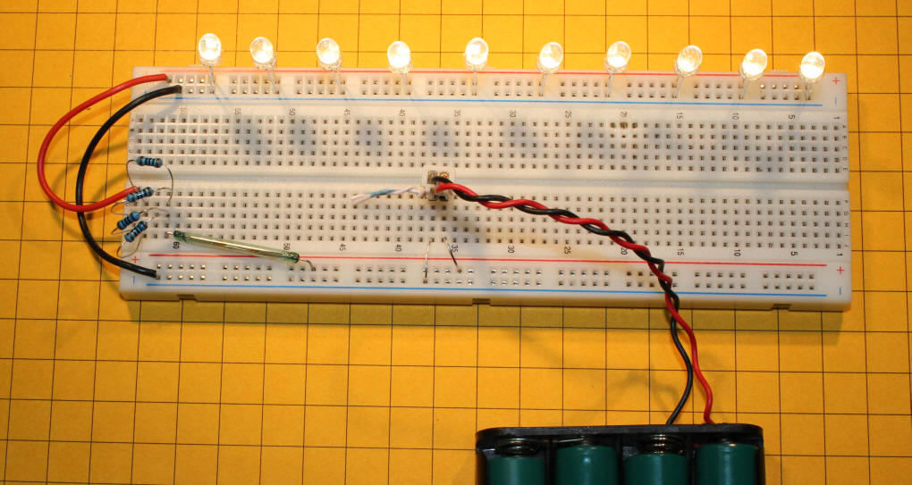
| An Alternative Test Setup Rather than using popsicle sticks you can also make a test unit that is functionally identical to the one above using a prototyping board. The resistors are in the bottom left along with the latching reed switch. The LEDs are plugged into the power bus at the top.
|
||||||||||||||||||||||||
| Video This video gives an overview of the test unit. (right click on the box below and select Play or click HERE) A Printed Circuit Board to Replace
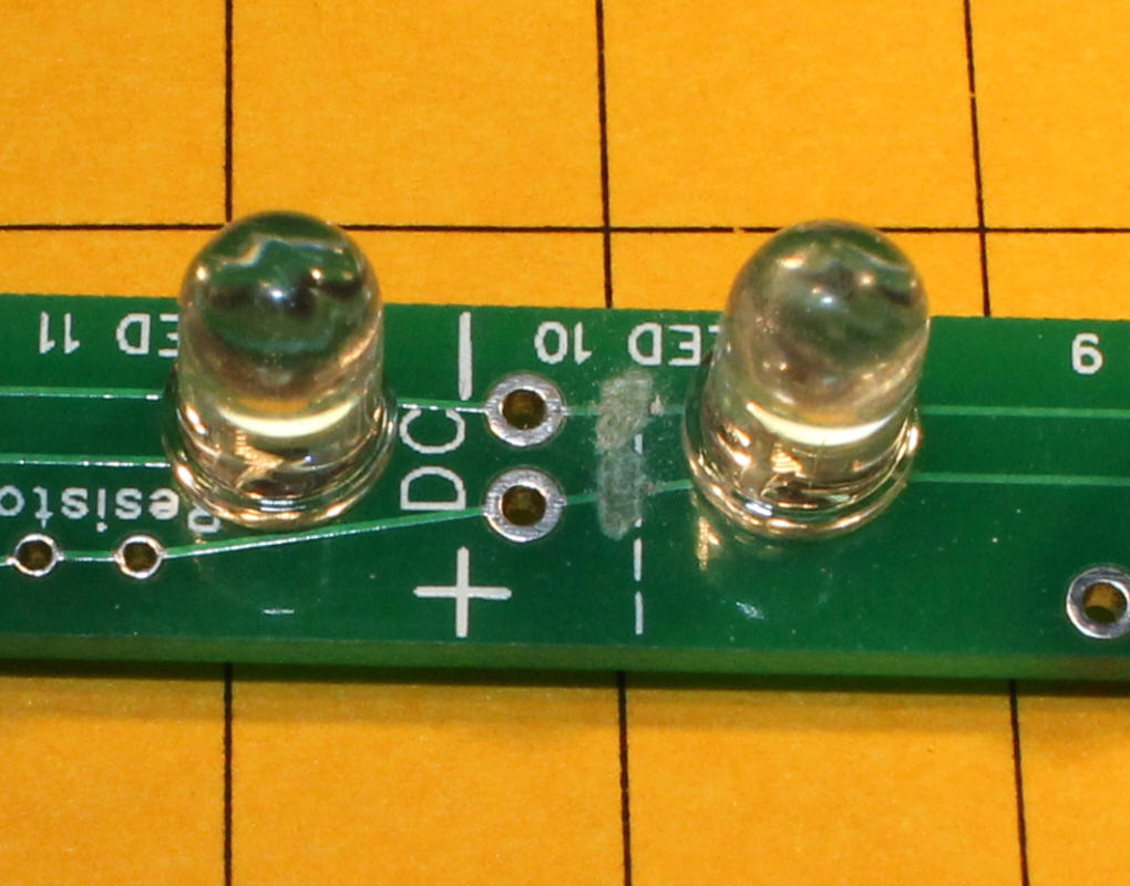
Popsicle Sticks! Since some users may not need to use current limiting resistors or reed switches the holes for those devices are joined by a "trace" that electrically bypasses them. In order to use a resistor you must cut the trace between the resistor holes with a knife. Similarly you must cut the trace between the Reed Switch holes to have the reed switch turn the unit on and off. Make sure you insert the resistor and reed switch in the segment closest to the power pins (the far left in the drawing) when you are using multiple 5 LED segments in one strip.
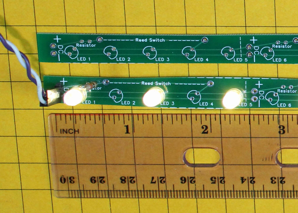
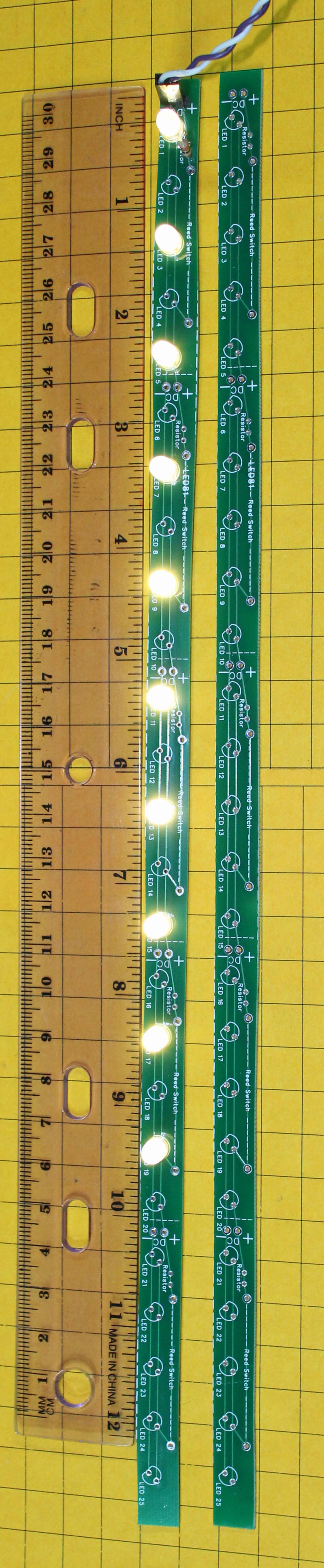
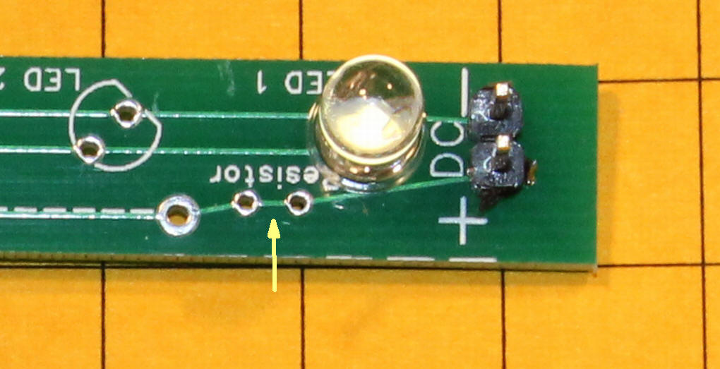
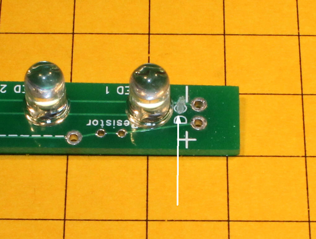
Here is a view of the whole printed circuit board. The board on the left has a current limiting resistor as well as a number of LEDs. The board on the right has not been populated as yet. You will note that only one resistor is needed for the entire board.
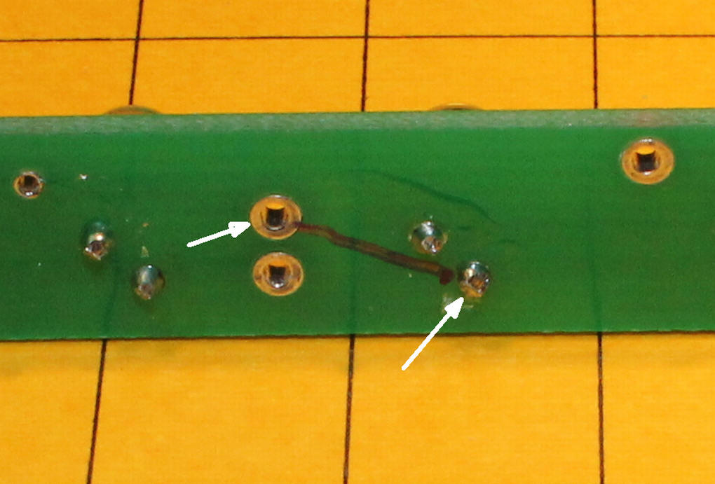
The yellow arrow points to the trace that connects, and bypasses, the resistor mounting holes.
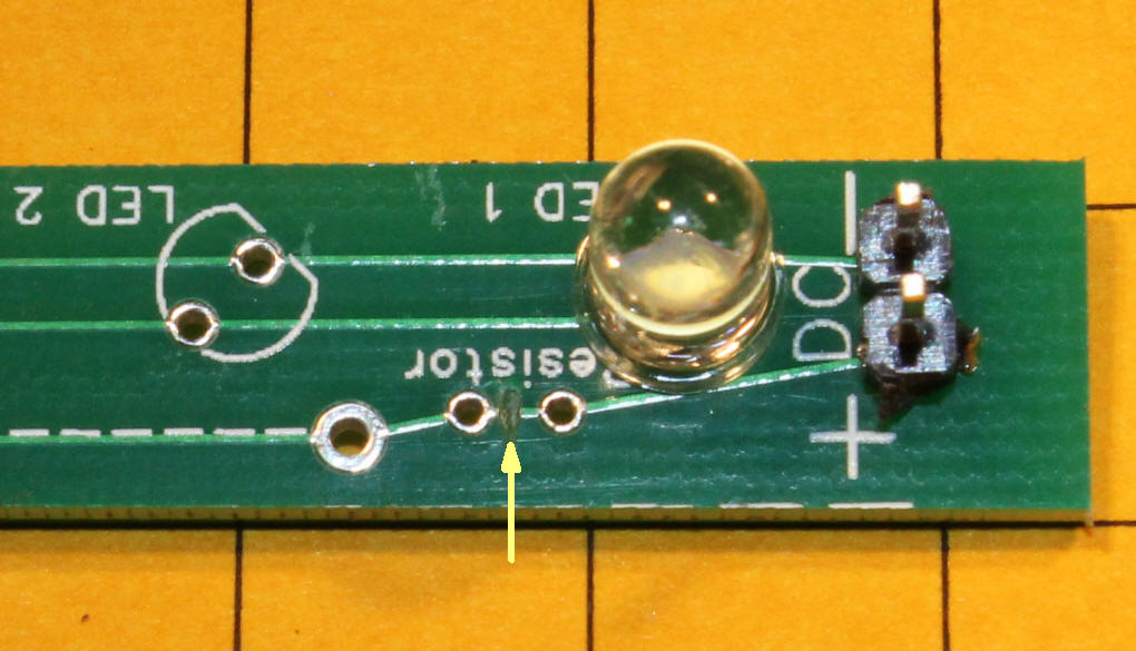
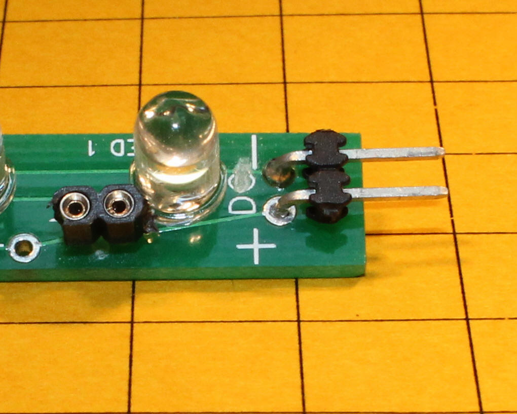
Here the trace between the resistor holes has been cut so that a resistor can be mounted in the holes.
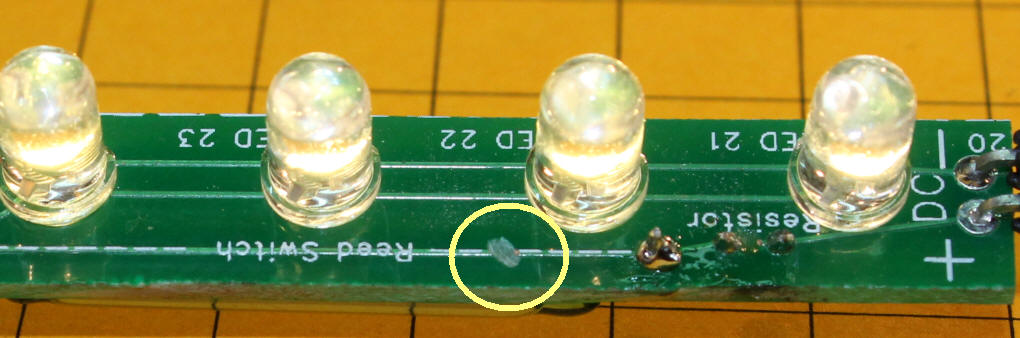
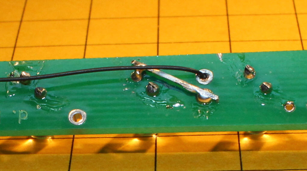
If a latching reed switch is to be used to turn the lights on and off you have to make a similar cut somewhere along the trace labeled "reed switch". Only the trace closest to the power input should be cut.
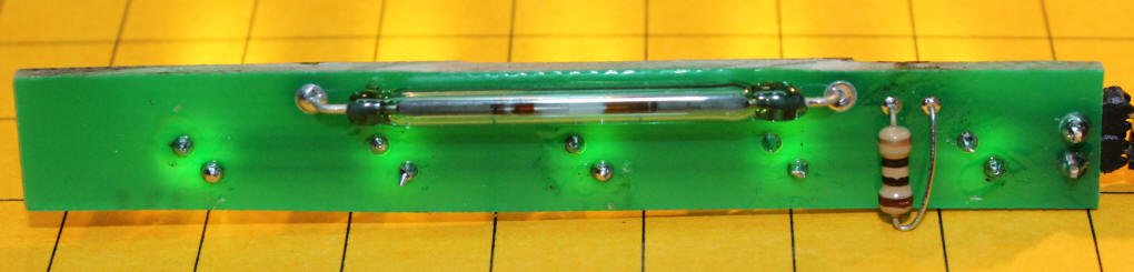
The reed switch can be mounted directly to the circuit board, as shown here, or it can be attached to a length of wire so that it can be mounted elsewhere. Note that the resistor for this board has been mounted on the bottom rather than the top. This makes it a bit less noticeable than when it is on the top of the board.
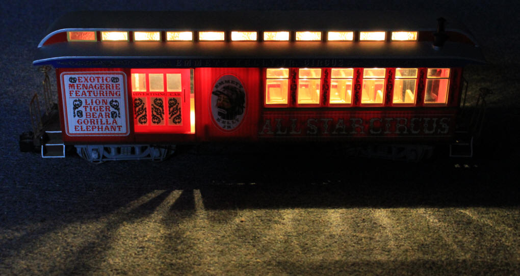
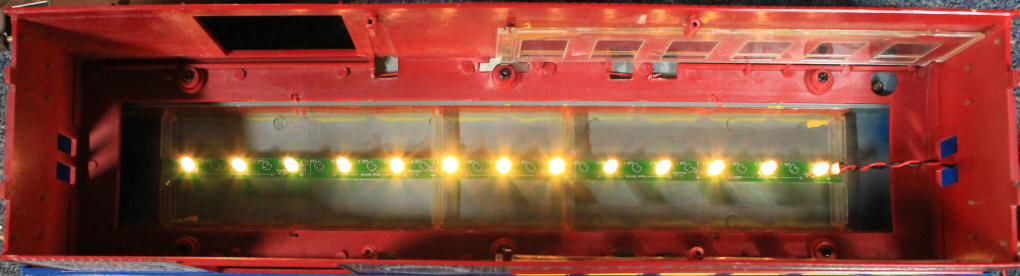
Here the LED circuit board has been mounted to the top of a coach. Thirteen of the 25 available LED locations on the board have been used. When 4.8 volts is used with a 33 ohm resistor it gives a very realistic looking effect. A photo of this car when seen from the outside is at the beginning of the article.
Resistor Wattage
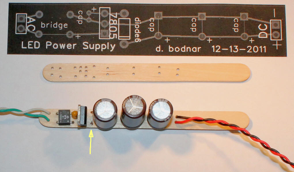
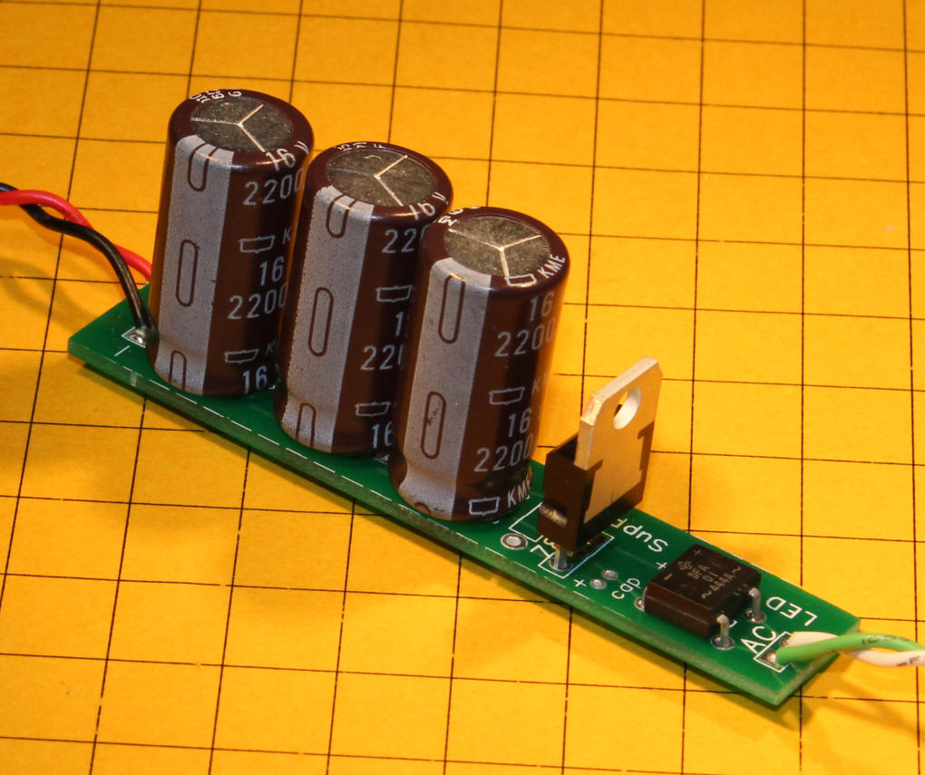
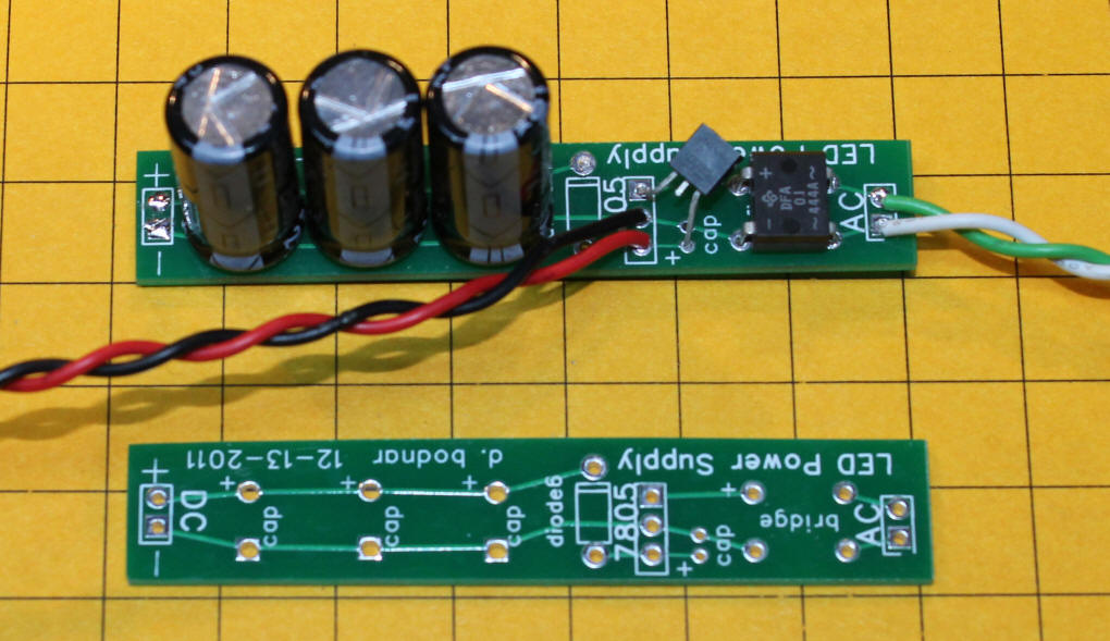
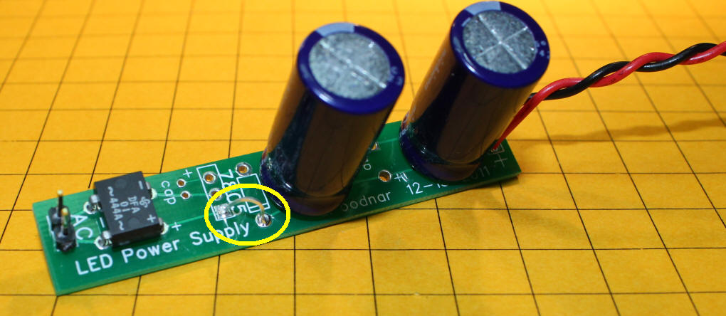
Track Power The top part of the photo below shows a drawing of a circuit board that I designed. While awaiting its arrival I made up a sample that is functionally identical using a popsicle stick. The first stick is drilled and the second is populated with (from left to right) a bridge rectifier, a small filter capacitor, a 7805 regulator, a small jumper (see yellow arrow) that takes the place of a diode and three 16volt, 2200 uF capacitors. The diode is not needed unless you are using special "supercaps" that are discussed below. In this case I just used a short jumper in its place.
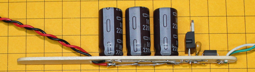
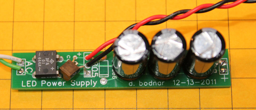
Here is another view of the same board. There are three 2200 uF / 16 volt capacitors wired in parallel. When capacitors are wired in this way their capacitance is added so they behave as though we are using one 6600 uF capacitor. This may sound like a high value but 6600 uF is only enough power storage to keep the LEDs from flickering, not enough to keep them lit for any length of time beyond a second or two if power is completely lost. To accomplish that we need to employ SUPERCAPS.
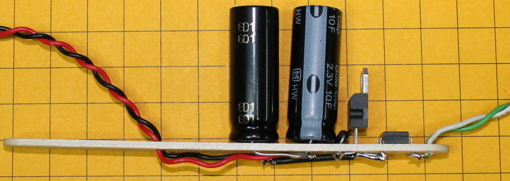
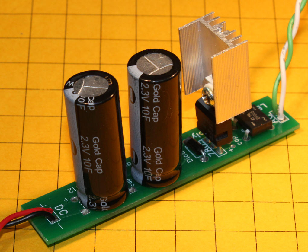
Here the three 2200 uF capacitors have been replaced with two 10F capacitors wired in series. They are wired in series because the voltage rating of these capacitors is only 2.3 volts and we are supplying 5 volts from the voltage regulator. The capacitors are wired in series with the positive lead from one going to the negative lead of the other, doubling their voltage to 4.6 volts but halving their capacitance to 5 F. The diode just after the 7805 drops the voltage another 0.7 volts to make sure we don't feed any more than 4.6 volts to the capacitors. You might not think that changing from 6600 uF to 5 F is much of a change in capacitance unless you know that there are 1,000,000 uF in a F (1,000,000 microfarads in a farad). This means the 5 F supercaps have 5,000,000 / 6600 = 757 times the capacity of the 6600 uF set of capacitors! These supercaps will keep the light shining for several minutes after the power has been removed. Supercaps are discussed in more detail in this article http://www.trainelectronics.com/Trolley_MrRogers/lights
Conclusion
Please let me know if you have any questions or suggestions (dave@davebodnar.com) |