Lighthouse Controller
Kit Construction
revise 05-27-14
| NOTE: This page has been revised to reflect the use of a more universal circuit board that can be used for this lighthouse circuit as well as the Morse code circuit. It can also be used with a PICAXE 08M or the PIC 12F683. For this reason there are a number of unused component locations on the board. |
(Click here to view the article on the lighthouse)
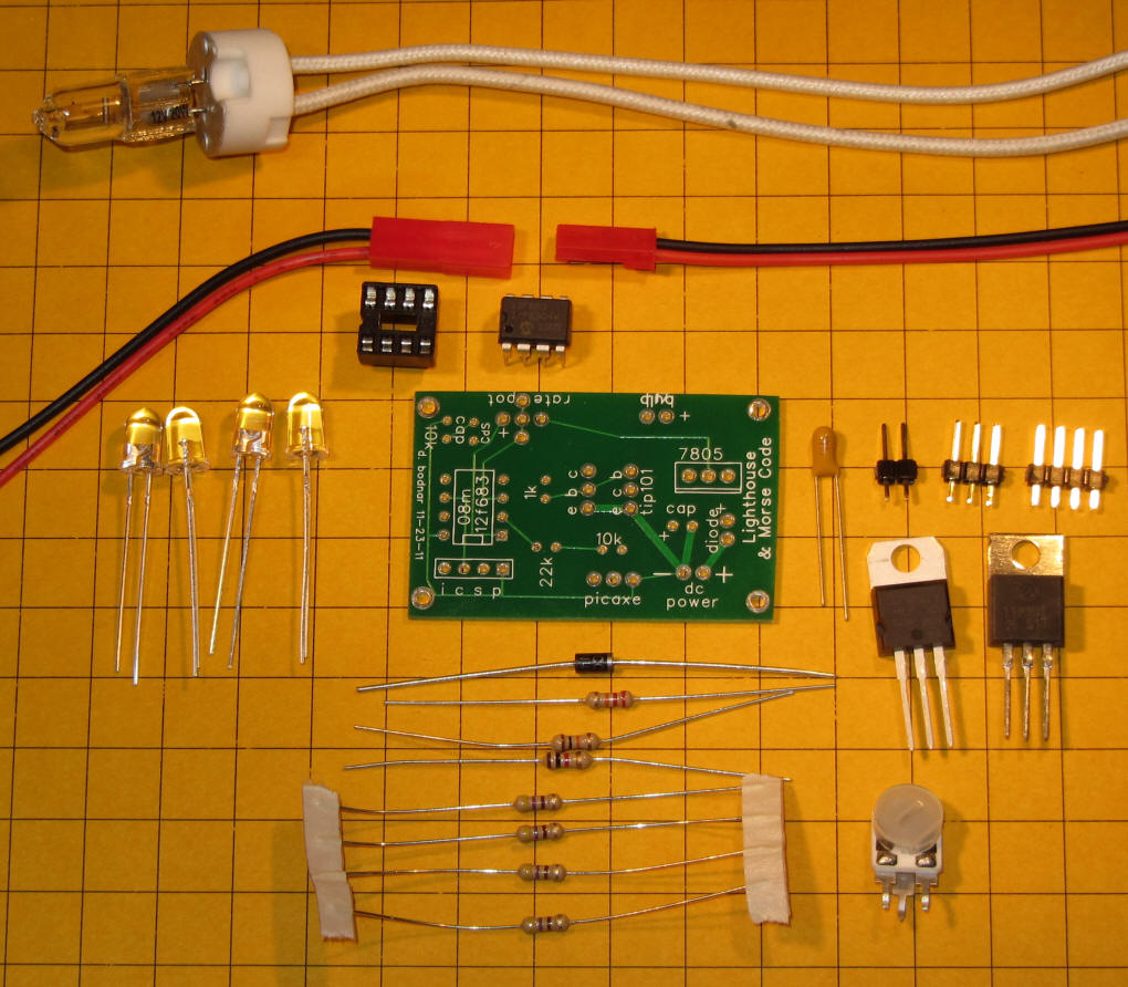
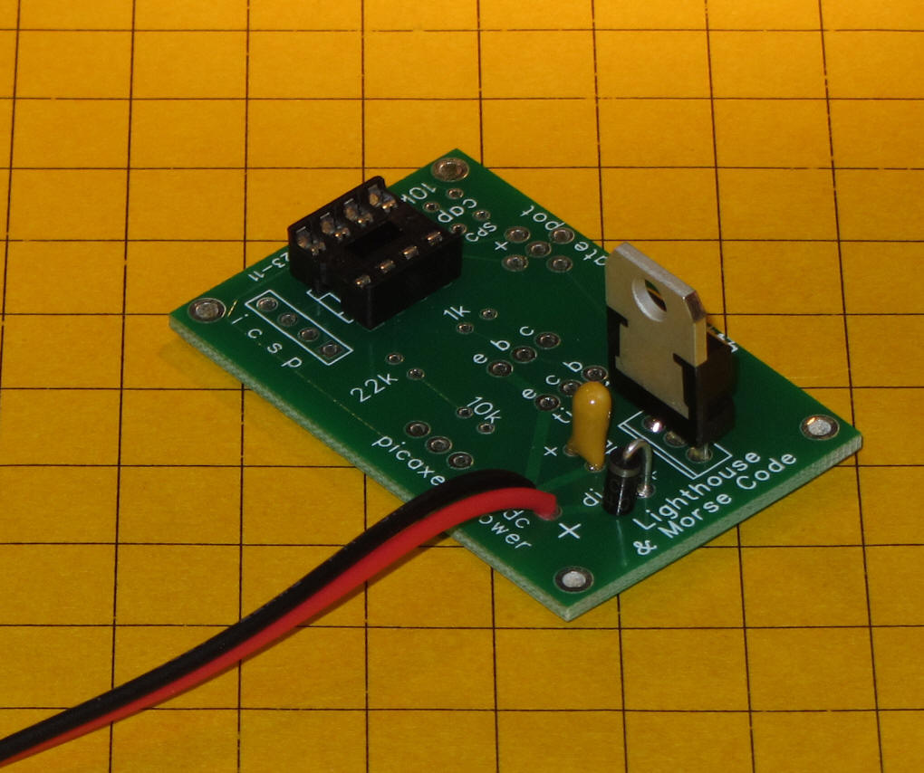
The first step in constructing the lighthouse controller kit uses the parts in this photo. The parts include:
Red/Black power cable (connect to source of 6-12 volts DC)
circuit board
filter capacitor (note pin marked as positive)
2 pin 3 and 4 pin headers (3 pin for PICAXE, 4 to program PIC)
7805 voltage regulator
10K resistor (brown/black/orange) - for PICAXE
22K resistor (red/red/orange) - for PICAXE
470 resistor (yellow/violet/brown) - x4
1K resistor (brown/black/red)
TIP101 Darlington transistor
10K to 100K potentiometer
diode (note silver band at one end)
8 pin IC socket
PICAXE 08M processor or 12F683 PIC processor
4 @ 5mm white LED or Halogen Bulb and socket
Additional parts are needed to implement the light sensor (CDs sensor) component for the lighthouse. These include a 10K resistor and the CDs sensor.
CAUTION: Please do not apply power to the circuit board before reaching the point in the instructions where you are directed to do so. Also, do not insert the PICAXE or PIC processor until asked to. Even though it is shown inserted in some of these photos it should NOT be inserted until the board is completed.
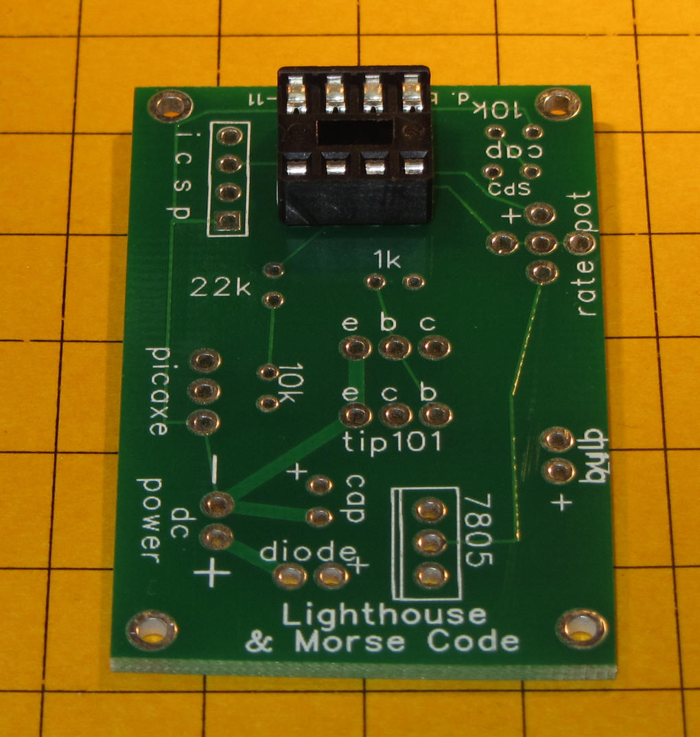
Place and solder the IC socket. Note that the notch in
the socket is on the left as shown in this photo. Double check the
back of the board for solder bridges before continuing.
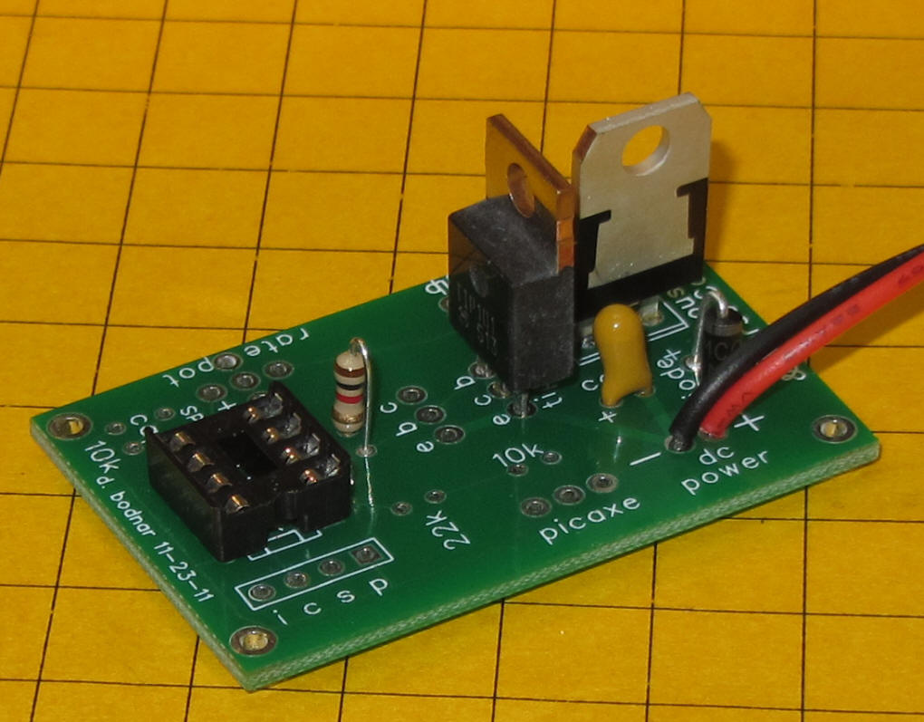
Insert and solder the filter capacitor - note that the "+" on the board must match up with the "+" on the capacitor. The "+" lead is usually longer, too. In the photo the back side (unprinted side) is away from the 7805.
Insert and solder the 3 pin 7805 voltage regulator. Note its orientation in the photo.
Again check for solder bridges
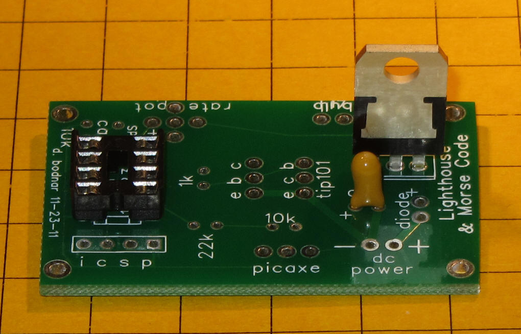
Insert and solder the diode as shown. Note that the silver ring on the diode goes towards the 7805.
Insert and solder the power connector. The red wire goes to the positive (+) contact and the black goes to the negative ( - ) contact
Temporarily attach power to the board through the red/black
wires. Set your volt meter to the 0-20 volt range and test to make
sure that 5 volts can be seen between pins 1 and 8 on the IC socket as
shown. 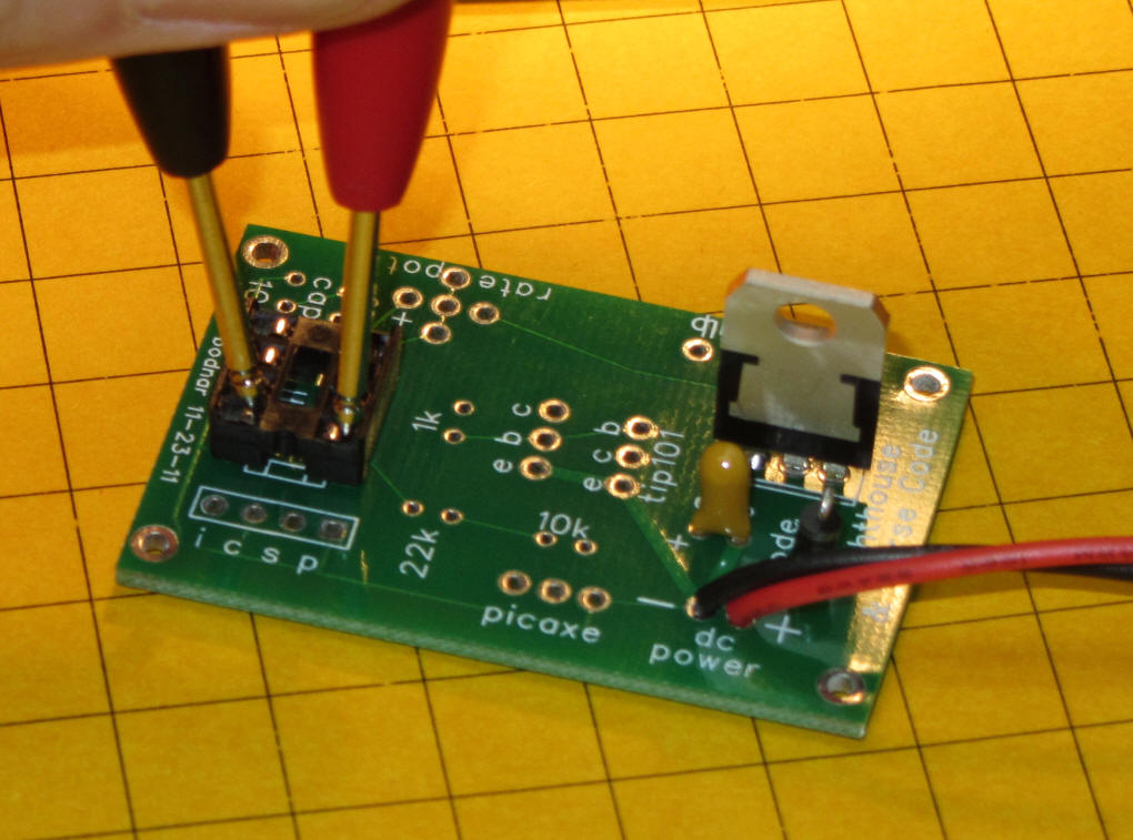
If you are going to use the PICAXE 08M microcontroller you
need to add the 10K resistor, 22K resistor and 3 pin header as shown.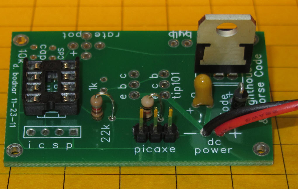
If you plan on using the PIC 12F683 and programming it using
ICSP insert the 4 pin header as shown. 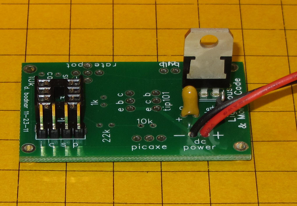
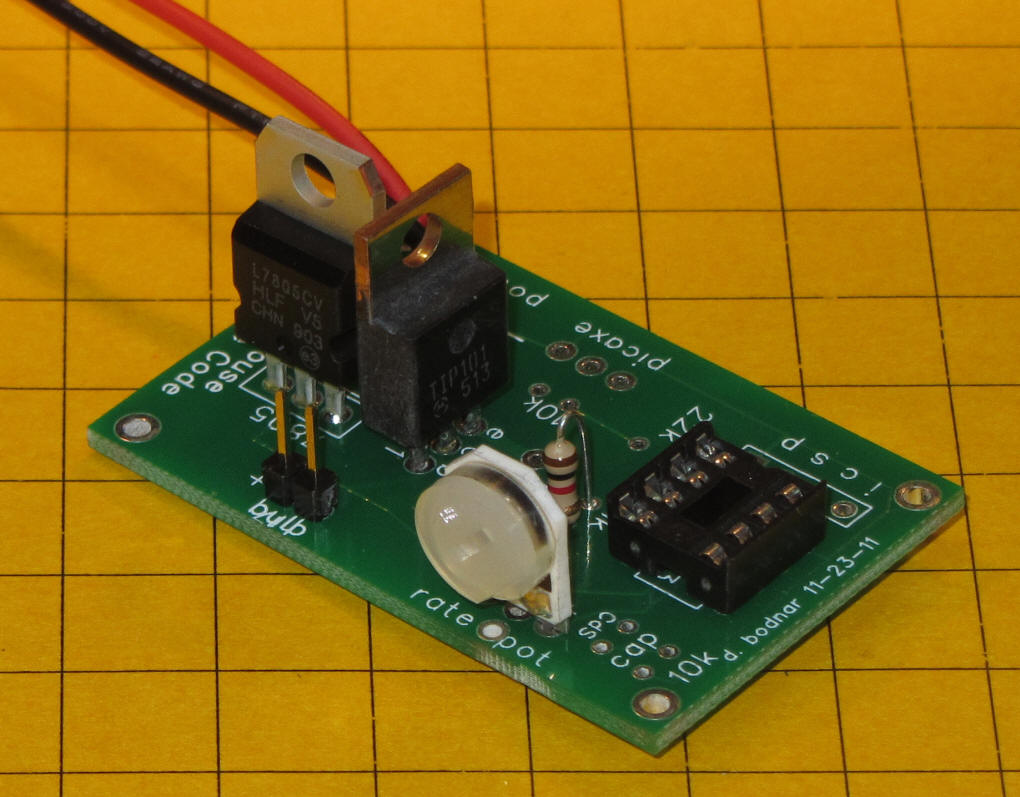
The TIP 101 transistor powers the lighthouse lamp. It
can deliver enough power to light the halogen bulb or many, many LEDs.
The TIP 101 and 1K resistor should be inserted and soldered as shown.
Note that there are a number of unused holes on the board near the TIP 101.
Be sure that the two metal tabs extending from the 7805 and TIP 101 do not
touch! A small piece of tape or heat shrink tubing can be used to
insulate one or the other.
Insert the potentiometer and two pin header for the light as shown. Solder and check for solder bridges.
Remove power and insert the PIC or PICAXE processor being sure to align the notch in the chip with the notch in the socket so that pin 1 on the chip goes to pin 1 on the socket.
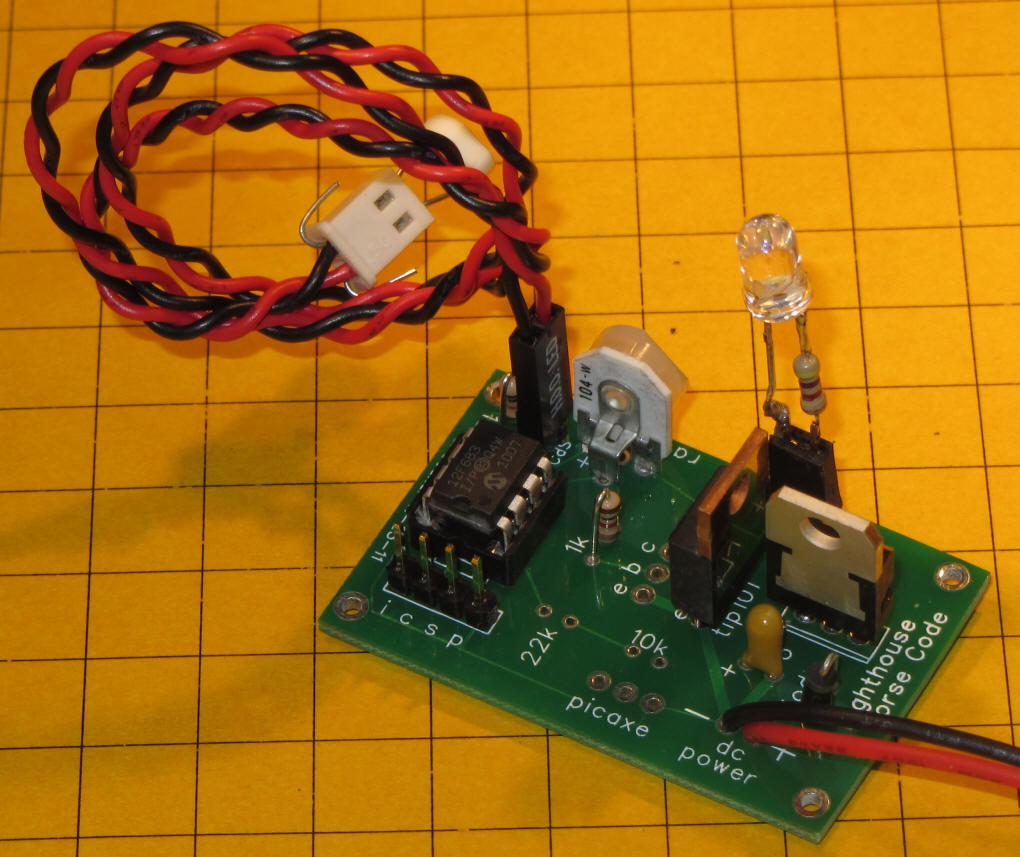
Here is the completed board.
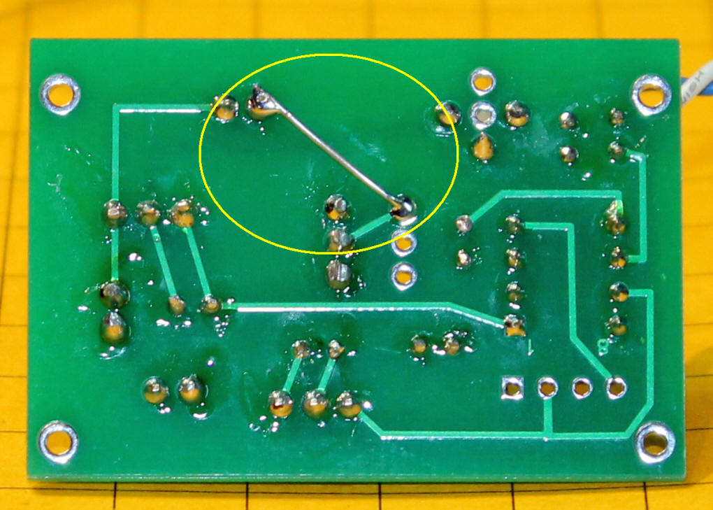
... and the bottom of the board. Check for solder bridges and poor solder
joints.
There is also one jumper that must be installed on the back of the board -
it is shown below (circled in yellow).
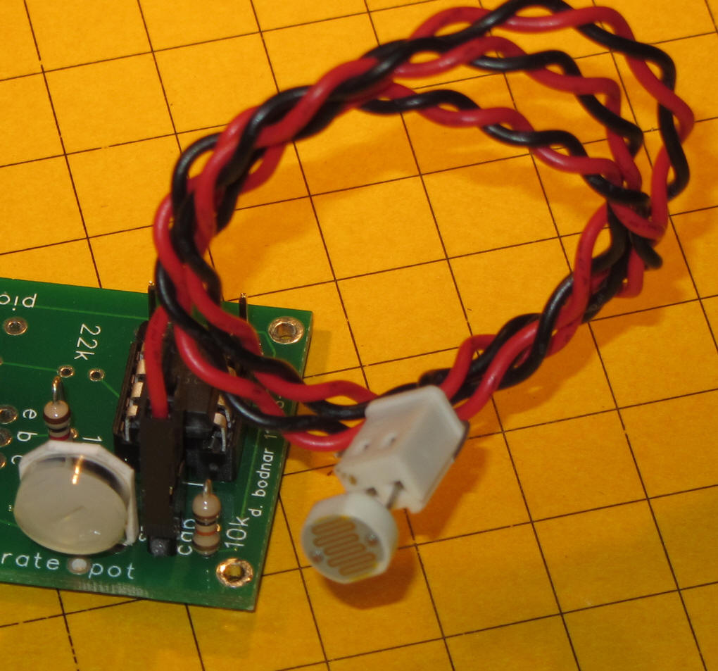
Light sensor option (CDs cell) - the unit can be made to
turn on power to the bulb only when it is dark. A CDs light sensor and
a 10K resistor are added to the circuit as shown. Note that the CDs
sensor is not directly soldered to the circuit board. A set of two
pins is inserted and soldered so that an extension can be used to move the
CDs cell off of the board.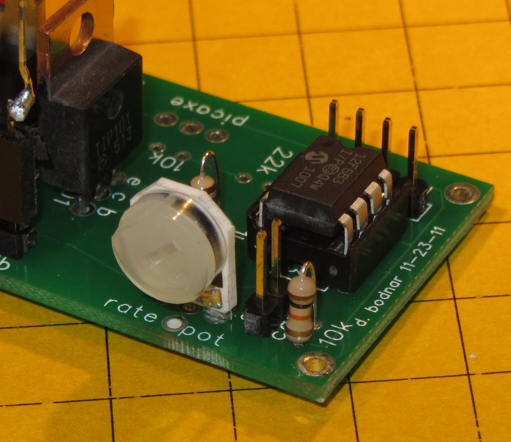
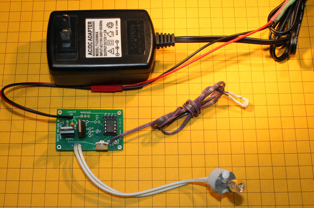
Here the CDs sensor can be seen on the extension wire.
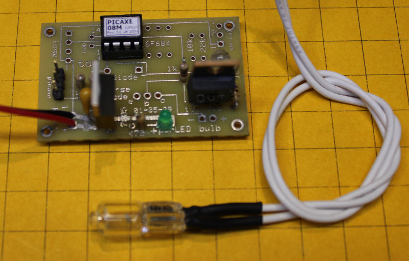
Halogen Bulb Option
If you are using the Halogen bulb it connects to the two pins just below the TIP101 that are marked "bulb". You can also connect multiple LEDs to these terminals. In order to properly illuminate the Halogen bulb you must supply 10-12 volts DC to the power pins. Do not exceed 12 or 13 volts or the bulb may have a significantly shortened life.
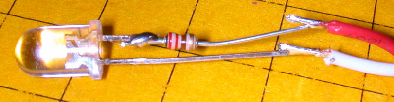
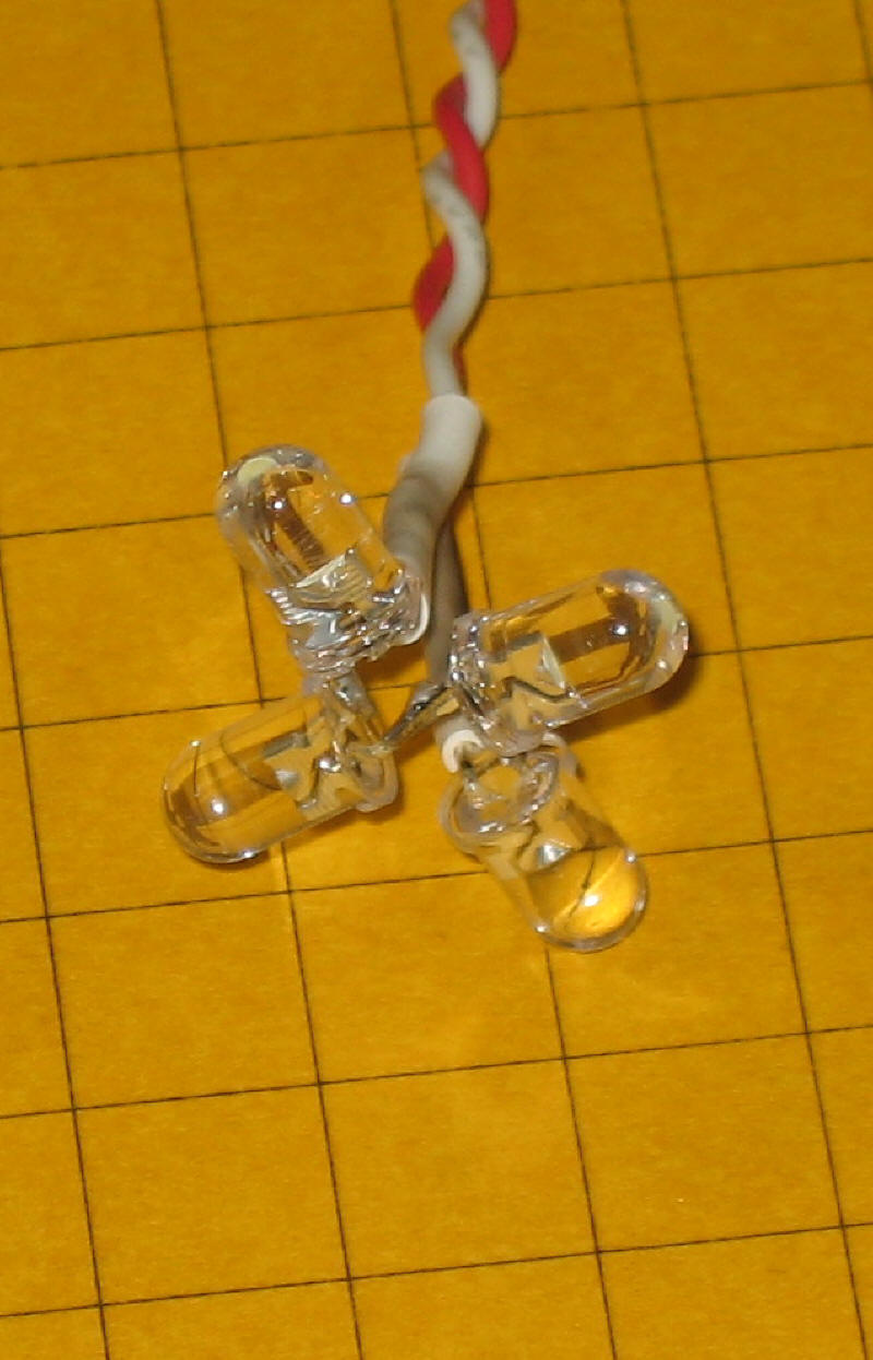
If you are using one or more LEDs with the unit the construction is the same as for the Halogen bulb. The LED must have an appropriate current limiting resistor wired in series with one of its leads. I routinely cut the positive (longer) lead and insert the resistor there. Here the cable that connects to the board has been soldered to the LED's negative lead (white wire) and the positive lead (red wire) - note the current limiting resistor. In this example the resistor is 200 ohms.
PICAXE Software (from article)
|
symbol some = 110
'delay constant b2=b2+3
'increase b2 by 3 for b1=1 to 200 step b2 'loop to dim LEDs b2=b2+3 goto start: ' ... do it again |
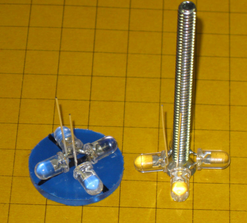
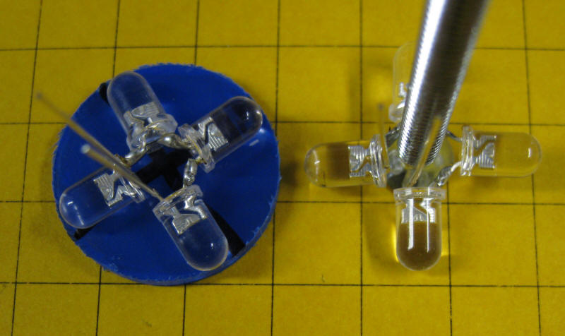
These photos show another configuration of 4 @ 5mm LEDs that will fit inside of a 1" tube with a space in the middle to allow an insulated 8-32 bolt to pass through.
In this photo a modified unit drives two sets of LEDs which plug in on the right. Note that the + and - (red / white) wires must be inserted as marked.
The latest version of the circuit is shown here (as of 1-2012). The halogen bulb is in the lower left. The optional CDs sensor is right of center and the new board with potentiometer is left center.