Lighthouse Lighting – A Bit More than On/Off/On/Off!
Revised 9/09/2011
click here for instructions
on constructing the lighthouse from a kit of parts
click here for information on an updated lighthouse circuit using very bright LED modules
"I really like my new solar powered lighthouse but the steady light is a bore. How can I make it blink or flash its light so that it looks more like a real lighthouse?"
Since I have written several articles for LSOL on LED lights and solar lighting of buildings this is a question that has been put to me more than once. It has also been a topic that has come up in the LSOL forums. I am always open to a challenge so I stopped at the local Wal-Mart and picked up several of their solar powered garden lighthouses and started to experiment. Well, folks were right about the lighthouses being boring. The ones I purchased lit up at night with a steady, but dim, amber light.
As you probably know real lighthouses don’t really blink on and off but contain a rotating lens system that sends out one or more focused beams of light. The time between observed flashes of light can be used by sailors to determine which lighthouse they are seeing as most lighthouses flash at rates that are well documented.
Although not really an accurate simulation, you might think that the simplest way to add a blinking capability to a solar powered lighthouse is to replace the original LED with one that blinks whenever power is applied to it. Radio Shack and other sources (see parts list) market such LEDs. As long as the voltage supplied by the solar lighthouse’s battery is sufficient it should work. You can determine if your lighthouse is likely to work with another LED by checking the number of NiCad or NiMh cells that are inside. Some solar lights work with a single AA NiCad battery. Others have two or more. If your lighthouse has at least two cells inside it should work with the Radio Shack blinking LED as the specifications for the light call for 2.25 volts and two NiCad cells @ 1.2 volts each should supply that much voltage. Unfortunately the fact that it “works” does not mean that it “works satisfactorily.” I have a few of the Radio Shack blinking LEDs and their light output pales next to that of the factory supplied LEDs used in most solar lighting devices. I don't think anyone would be satisfied with this option.
Another issue is the color of the LED. Although some real lighthouses use red lights, most do not. I have come across several sources for blinking LEDs in colors other than red but none that operate on a less than 3.5 volts and none that put out white or bluish white light, a better choice for a modern lighthouse.
SIMULATING A REAL LIGHTHOUSE BEAM
If you are willing to replace the lighthouse’s small solar panel with an external panel such as the ones described in my article “LED Lighting with Larger Solar Panels” (LED Lighting with Larger Solar Panels ) or with an external power supply your options increase dramatically. Not only can you use LEDs that require a higher operating voltage but you can make the blinking much more realistically represent what you see when you see light from a real lighthouse.
To an observer a good distance removed from a lighthouse the light is first seen dimly, slowly increasing in intensity until it flashes brightly as its focused beam hits your eye. It then dies out slowly as the beam retreats. This is not at all what happens with a simple flashing LED that is turned on / off / on / off repeatedly.
To properly simulate a lighthouse’s light you need to utilize a more sophisticated circuit that can vary the intensity of a light from off to full brightness and back to full off again in small steps that make you think you are seeing a rotating light. Although such a circuit can be designed and constructed using simple components including several 555 timers, the parts count is quite high and it can be very tedious to adjust the part values so that just the right “feel” is attained.
To complicate matters even more the change in intensity does not follow a linear path or curve. If that were the case we could increase the brightness in even steps.
A lighthouse light does not change as represented by this linear graph.
The actual change in brightness that is perceived by the human eye more closely resembles a mountain with curved sides and a steep peak. It starts up slowly and gets more and more steep until it peaks and then decreases in a similar manner, as illustrated in the diagram below.
This curve more closely represents what you see emanating from a lighthouse.

![]()
Picaxe to the Rescue
While doing research for this article on the Internet I came across one commercial unit that seems to do some of what is described above, it lacks the flexibility that I was looking for so I decided to design one myself. To keep the parts count down and to facilitate construction, my favorite way to deal with projects such as this is to design a simple microprocessor based circuit and change the software that drives the system to make adjustments to the light. The Picaxe (www.picaxe.com) is a simple 8 pin microprocessor that is ideally suited for this task.
| NOTE: The following information is for those of you who might be interested in building this circuit from parts. For those of you who that would prefer to work with a completed unit or a complete kit of parts please see the options available at the end of this article. |
Let’s start out with a basic circuit that runs off of a 4.5 to 4.8 volt power supply made up of three AA alkaline or 4 NiCad or NiMh cells. Later on we can explore running the whole thing off of solar, AC adapter or track power. Please note that you cannot use batteries that supply more than 6 volts or the Picaxe will be destroyed. Since there is no voltage regulator in this simple circuit you must take care to provide the proper voltage.
The circuit is below. As you can see the batteries are connected to pins 1 and 8 of the Picaxe microprocessor and a single transistor is used to control the power to the LED(s). The references to ground indicate places that need to be connected to the battery’s negative terminal and references to +5v connect to the battery’s positive terminal. The large plug on the left and the two resistors (R1 and R2) that connect it to pins 2 and 7 on the Picaxe are used to program the device. If you opt to use a preprogrammed Picaxe (see parts list) they are not needed.
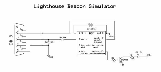
Please note that the single LED and resistor can easily be expanded by wiring additional LEDs and resistors in parallel. Since LEDs send out a focused beam it is wise to use several in an application like this not just to increase the brightness but to allow you to focus each LED in a different direction. This enhances the chances that observers are looking at the brighter "end" of an LED. The circuit detail below shows how additional LEDs can be added.
The transistor, an NPN (2N3904 or equivalent), is used as a simple switch that turns the LED(s) on or off based on whether Picaxe pin 5, which connects to the transistor’s base lead through R3, is on or off. If only one or two LEDs were used to light the lighthouse the transistor could be eliminated and the LEDs connected directly to the Picaxe. The use of the transistor, however, allows us to connect a great number of much higher power LEDs and there is no risk of overtaxing one of the Picaxe's output pins and damaging it.
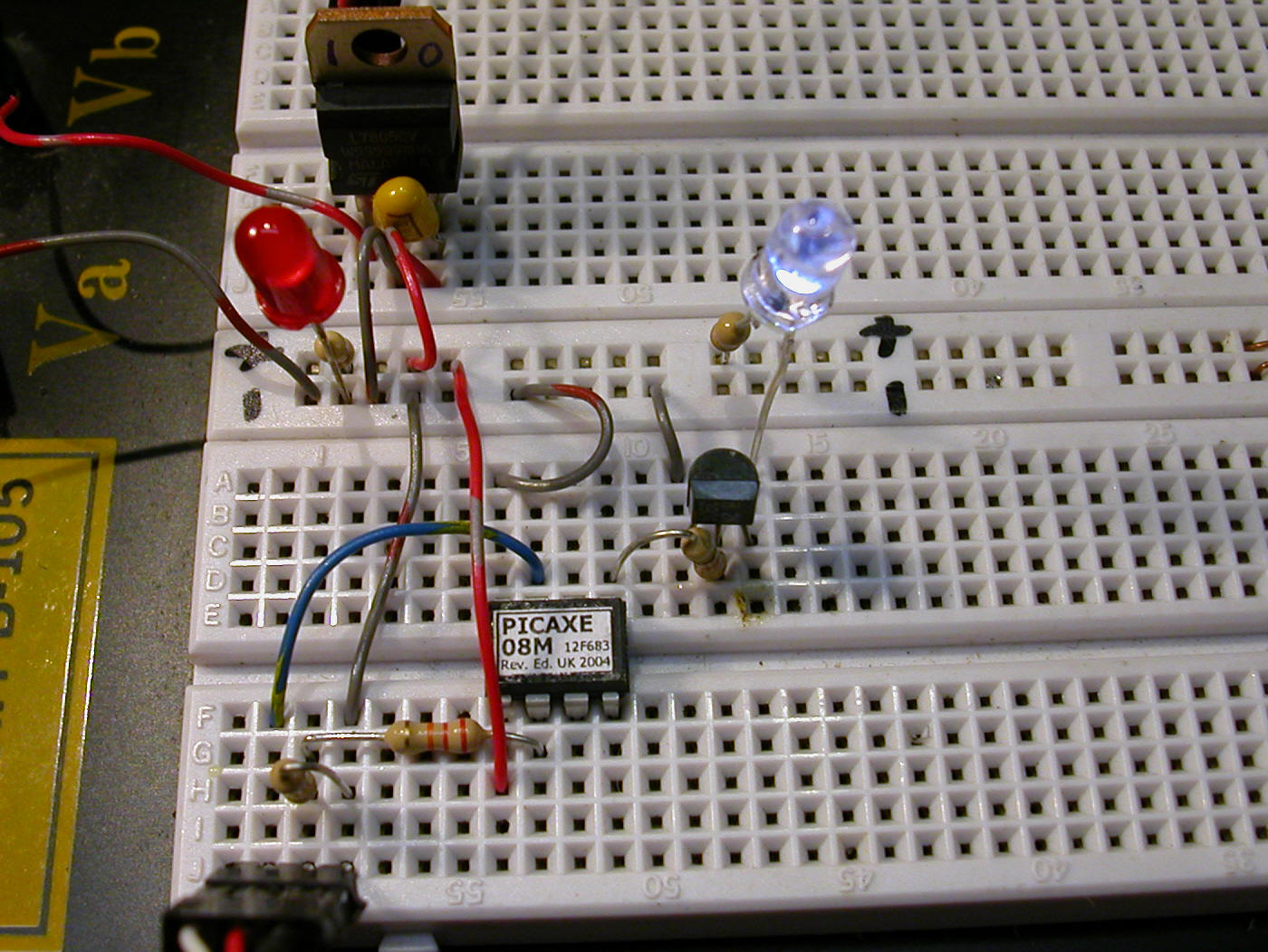
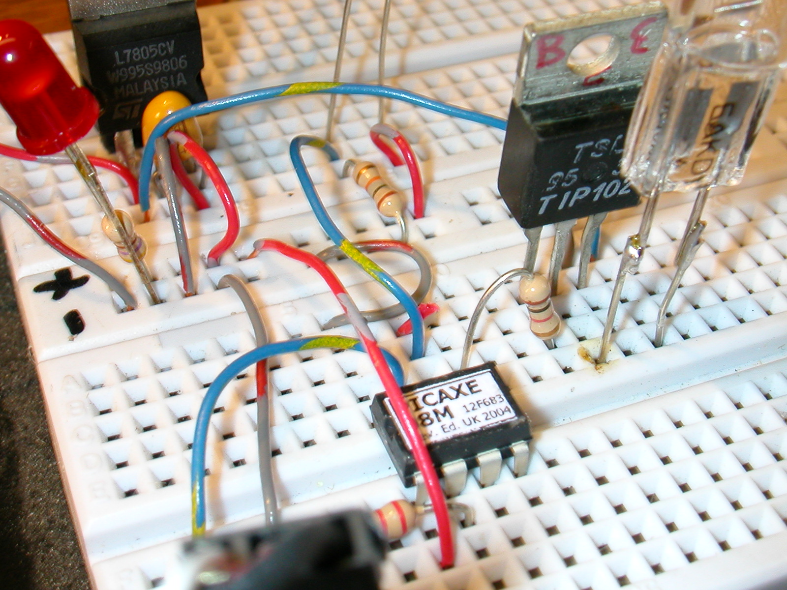
Breadboard Prototype
I like to build prototypes of circuits on small breadboards such as the one pictured below. I described how these work in a previous article on infrared sensors. The important thing to note is that the breadboarded prototype follows the wiring that is shown in the schematic. The only addition is the voltage regulator in the upper left corner that needed since this test setup is not running off of batteries. The red LED (left center in the photo) just shows that power is on. The clear LED (right center) is the lighthouse light. The transistor that drives the lighthouse LED is just below it. Note the resistor connecting the Picaxe's pin 5 to the transistor's base lead. The plug in the lower left is the programming connection to the computer.
Once you have breadboarded the circuit and have it working properly it can be transferred to a more permanent board where components are soldered together.
Custom Circuit Board
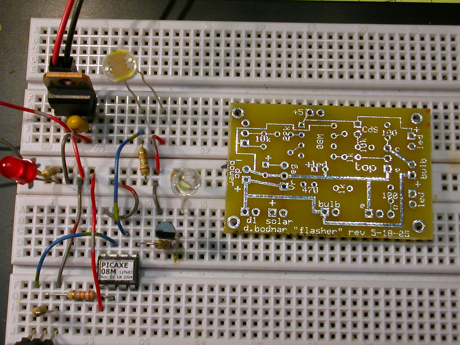
Since a number of my friends and I really liked the way that this project turned out I decided to have circuit boards (see photo below) made up to facilitate its construction. If you are interested in this circuit board or in a wired and tested board please see the notes in the parts list. By the way, if the custom board looks like it has places for many more components than those used on the bread board you are right! The board can be used for several variations on the circuit that is on the bread board.
Software for the Picaxe
The BASIC program that controls the Picaxe is very simple.
In the first program below the Picaxe is programmed to turn the LED on, pause 2 seconds then turn it off and pause for another 2 seconds and repeat.
|
Start: High 2 ‘turn pin 5 (out2) on Pause 2000 ‘wait 2 seconds (2000 1/1000ths of a second) Low 2 ‘turn pin 5 (out2) off Pause 2000 ‘wait 2 seconds (2000 1/1000ths of a second) Goto start: ‘go to the start and repeat forever |
You see that this program does little more than turn the LED on and off. Not exactly what we wanted!
To vary the brightness of the LED we use a technique called PWM or Pulse Width Modulation. PWM overcomes a limitation of digital devices where pins are normally off (showing 0 volts) or on (showing 5 volts). In PWM a pin is turned on and off rapidly, simulating a varying voltage. By changing the width of the pulse and the duty cycle, that is the time during each pulse that the pin is ON, we can control the brightness of the light over a great range. In the program below the PWMOUT command is used to send pulses to the pin connected to the LEDs.
|
symbol some = 110
'delay constant b2=b2+3
'increase b2 by 3 for b1=1 to 200 step b2 'loop to dim LEDs b2=b2+3 goto start: ' ... do it again |
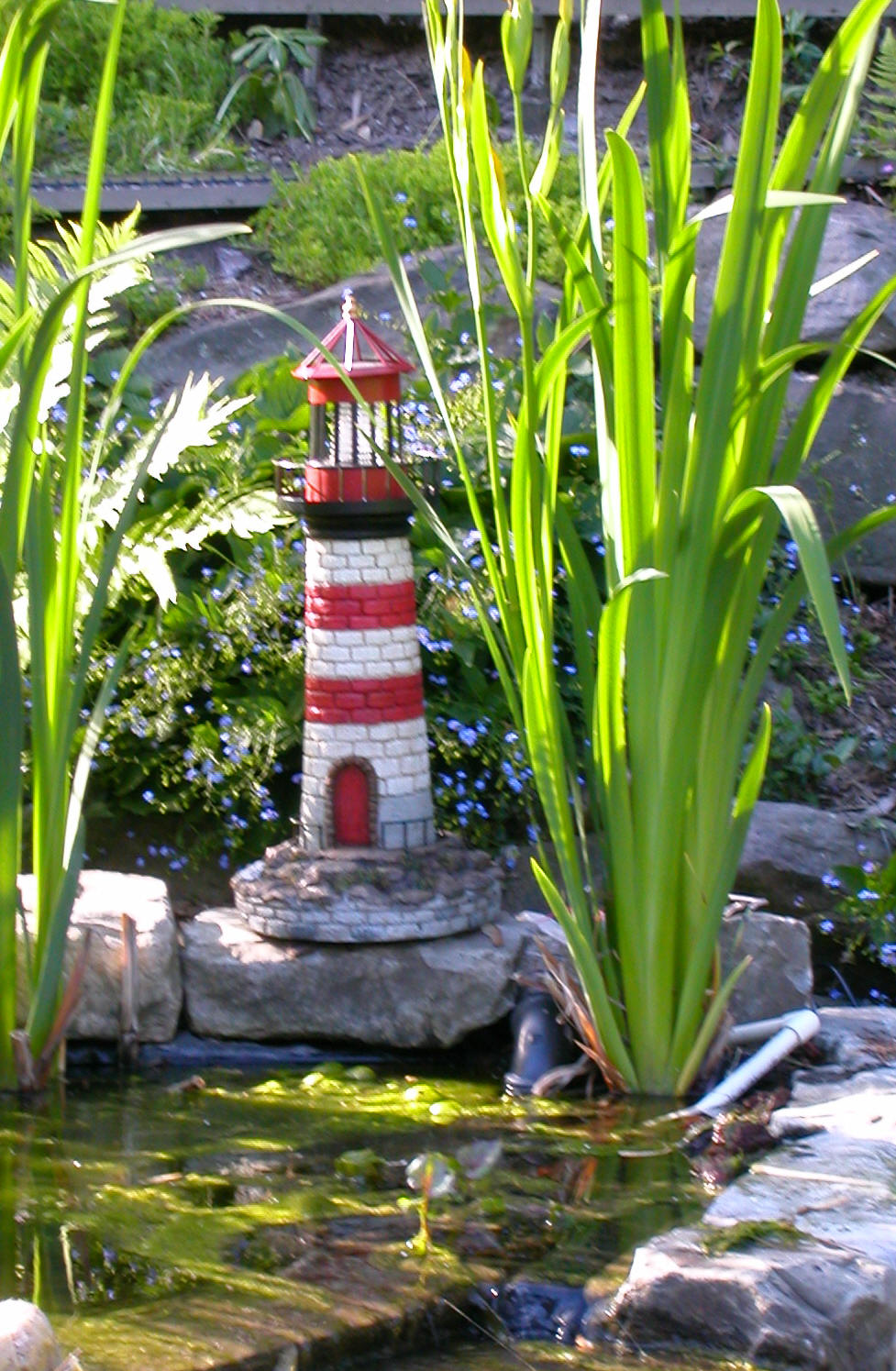
Installing LEDs in a Wal-Mart Lighthouse
I recently purchased two of the Wal-Mart lighthouses and converted them so that the light that they give off more closely resembles that of a real lighthouse. One of the conversions was to LED lighting and the other much brighter conversion was to a 10 watt, 12 volt halogen bulb.
The Wal-Mart lighthouses that I have found and seen mentioned in the LSOL forums are a great value. They are nearly 2 feet tall and have a highly detailed cast resin base and a very nicely detailed metal head that has a railing, clear light diffuser and roof.
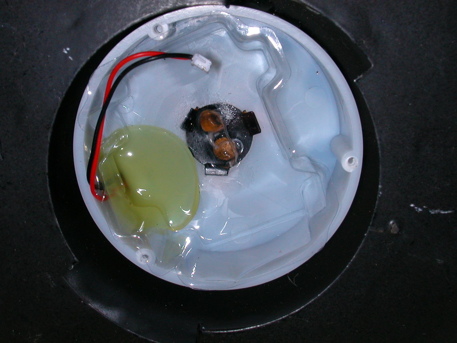
The first step in converting the lighthouse to flashing LED lighting is to remove the existing lighting system, consisting of a case, two NiMh cells, two amber LEDs and a circuit board. The system also has a 2” round solar panel at the top of the lighthouse. This can be removed by bending the tabs that hold the very top section of the roof to the part below it, exposing the solar panel. If removed you will want to replace it with a black circle of plastic or metal as it will leave a large hole where it had been mounted. If you are not planning on using the solar panel in another project just leave it there.
Remove the top of the lighthouse by giving it a ½ twist and unscrew the three silver screws that hold the white control box into its base. On one of the lighthouses, the blue one, the only thing left holding the box in place was its connection to the solar panel. This connection is through a small plug and it can easily be separated. The other lighthouse, the red one, had three plugs that held the board and the other components to the lighthouse frame. One from the solar panel and two from the two LEDs. It was a good bit more difficult to remove, especially because of the LEDs. I gave up on trying to salvage them as they were glued in place.
Note that there may be more variations on how these lighthouses are constructed as I purchased two and found two different methods of installation. I also found that the level of difficulty in removing the existing lighting system was directly proportional to the amount of hot melt glue that was used during the initial fabrication of the unit!
On the inside of the base of the blue lighthouse you will see a clear plastic housing that has two indentations where the LEDs are inserted. This housing is there to keep rainwater from getting into the circuit box but it needs to be removed. I found that a razor knife and pliers did a good job of removing it. Once it is out you will see two LED sized holes in the bottom of the base. Since we are going to insert 5 LEDs that hole will need to be enlarged. A pair of side cutters and pliers opened the hole up nicely. I trimmed it a bit more with a small grinding bit in my Dremel.
On the blue lighthouse I left the white case insert in place as it appeared to be thoroughly glued to the metal under it. The one in the red lighthouse was only held in by a small amount of glue and three metal tabs. Bending the tabs back and prying up with a screwdriver freed it easily.
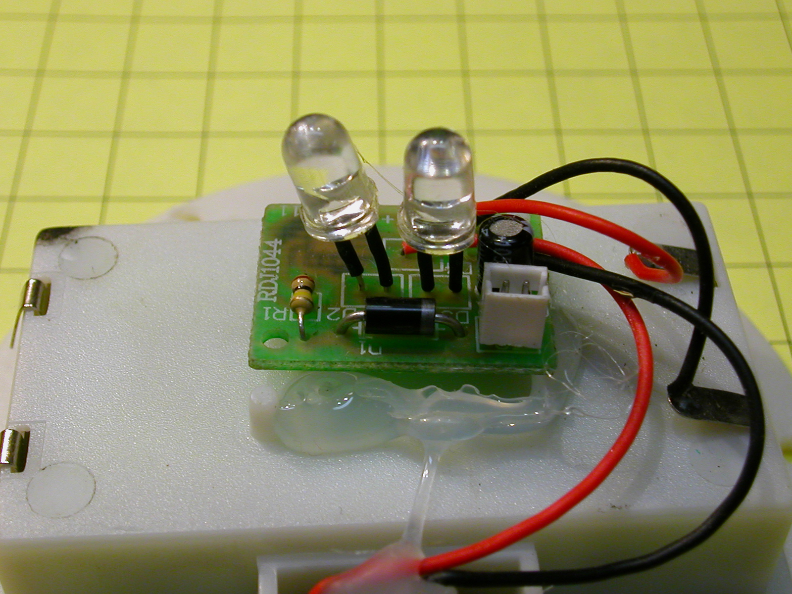
In order to get a brighter light from the lighthouse I chose to use 4 bright white (bluish white, actually) LEDs in place of the two amber ones that came with the unit. The LEDs are wired in parallel, each with a 100 ohm resistor on its positive (longer) lead. The LEDs can be stacked as seen in the photo to more easily insert them through the small hole that you just made. Since there is a reflector at the top of the diffuser on the lighthouse the LEDs should all point up so that their light can be properly dispersed.
Here are the LEDs with just the center (negative) leads soldered and...
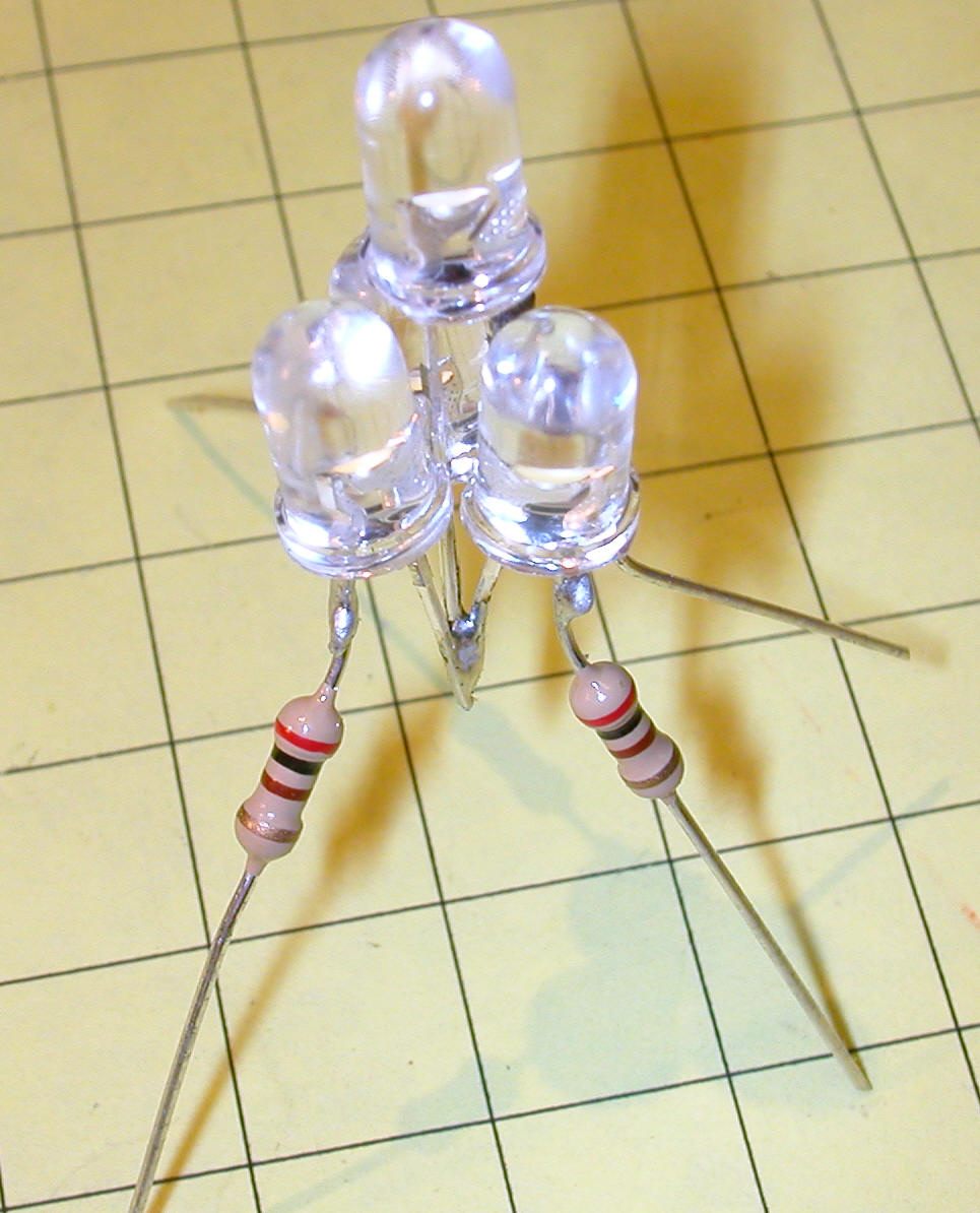
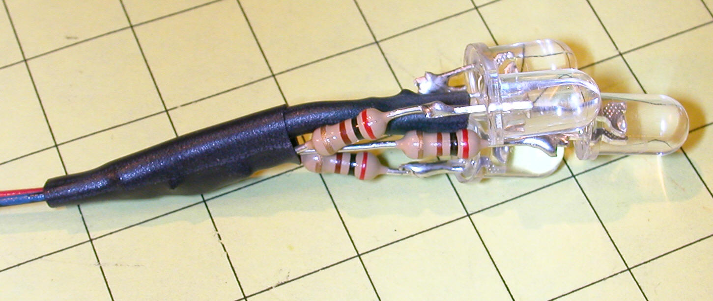
completely wired, insulated with heat shrink tubing and ready to insert in the top of the lighthouse. Notice that each LED has its own current limiting resistor soldered to its positive lead.
The circuit board easily fits into the space at the base of the lighthouse’s top where the original white plastic box was removed. Since the lighthouse base is hollow a small hole in the top and another in the bottom were drilled to allow wiring to pass through so that it was possible to use an external power supply. Make sure you take steps to protect the circuit board from water. Rain will go through the opening you made in the lighthouse unless you completely seal it. Another option is to encase the circuit board in a small watertight box or at least a box that is sealed on the top and sides so that seeping water flows around it and can't get in. If the unit is allowed to get wet it is only a matter of time before it will fail.
Installing a Halogen Bulb in a Wal-Mart Lighthouse
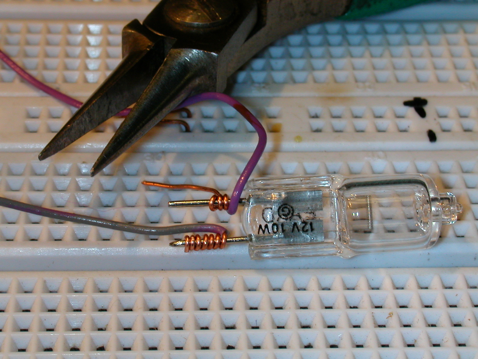
LEDs do a nice job on the lighthouse but don’t give nearly the dramatic effect that you can get when you use a really bright halogen light bulb. The bulb I chose to use is a 10 watt, 12 volt halogen bulb. They are sold at Wal-Mart, Home Depot and similar outlets for a few dollars each. These are the bulbs that are used in many low voltage, high intensity lights. They are bright enough to temporarily blind you if you stare right into them.
There are several issues that need to be addressed with the use of these bulbs.
First, you rule out solar power unless you use one or more fairly large solar panels, such as the ones described in my solar power article. Since my lighthouse was going to go near the pond, where I have access to AC power, I chose to use a small 12 volt power supply.
Secondly, the circuit needs to be modified a bit as the 2N3904 transistor can’t handle the current drawn by the halogen bulb.
Third, the halogen bulbs are not going to last anywhere near as long as the LEDs. For this reason you need to consider bulb replacement as you mount it in the lighthouse. Don't glue things in too permanently!
Most halogen bulbs have two connection pins coming from the bottom of their glass bulb. These are frequently made of a metal, perhaps stainless steel, that does not readily accept solder. For this reason I generally strip an inch or so of the insulation from a piece of wire that I wish to connect to the bulb and tightly wind it around one of the pins. I repeat with a second wire to the other pin.
To extend bulb life you may not want it to flash during the day although it will surely be visible. If you don’t want to put it on a switch or timer a simple circuit modification, using a CdS photocell attached to the Picaxe, can be made. It will then turn the lighthouse on at dusk and off at dawn. Information on how to do this is at the end of the article.
The final consideration is something that came up the first night I had this lighthouse running in the back yard. Since our bedroom faces the pond every 18 seconds the light from the halogen bulb found its way between the slats of our Venetian blinds and the ceiling of the bedroom was briefly illuminated. Needless to say, that lighthouse was quickly replaced by the LED illuminated one that is much less likely to disturb one's sleep!
The transistor I used in place of the 2N3904 is another NPN device, the TIP102. It can easily handle the current drawn by the halogen bulb. The LED circuit used the same 5 volt power supply to power the Picaxe and the LEDs. In this version the Picaxe and the halogen bulb can be powered from the same 12 volt power supply, but a 7805 or 78LS05 voltage regulator must be used to deliver 5 volts to the Picaxe.
The schematic is modified to accommodate the voltage regulator and to provide 12 volts to the halogen bulb through the TIP102.
One important thing to note in the schematic and the photo below is that the halogen bulb does not get its positive voltage from the output of the voltage regulator or another source of 5 volts as was the case with the LED. It is connected directly to the source of 12 volts on the regulator's input pin. If you connect it to 5 volts it will work but not very brightly.
Photocell Auto On / Off Modification
A CdS photocell is a simple electronic component that is used in many household devices that turn something on when it gets dark and off when daylight returns. The resistance of the CdS cell varies based on the amount of light hitting it. When dark its resistance is very high, typically 30,000 to 40,000 ohms or more. In bright light its resistance can drop to a few ohms. The Picaxe can easily be programmed to note the change in resistance, completely halting the program and darkening the lighthouse until darkness comes.
The modification to the breadboard circuit is shown below and in the schematic in the next section. The CdS sensor is the object with the "S" curves on its face at the top of the photo just to the right of the voltage regulator. Note that the CdS cell is connected to the Picaxe at pin 6. That pin is also connected to ground through a resistor to make the pin "low" when the CdS cell is in darkness.
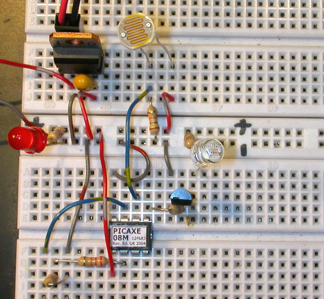
The CdS cell can be inserted into the same cavity as the LEDs or halogen bulb. Just place it at the bottom of the area off to one side. Since we will not be testing for light when the bulbs are lit it can be placed next to them and still be used to find if the sky is bright or dark.
Solar Powering the LED Flashing Circuit
To power the LED circuit from solar cells you can add a solar panel and 6 NiCad or NiMh rechargeable cells to the circuit as shown below. The solar panel must put out at least 8 or 9 volts in sunlight to charge the battery. Note that the schematic includes the CdS photocell option so that power is preserved during the day and only used when it is dark.
If you would like to experiment with solar powering the halogen bulb light I would suggest making these changes to the circuit. First, use 10 NiCad or NiMh cells to give you a 12 volt power source. Make sure that your solar panel(s) can supply enough voltage to charge this battery. This setup is likely to work but is unlikely to keep the light flashing throughout the night. Let me know if you get it to work!
Software for Daylight / Night Sensing with CdS Cell
|
symbol some = 110 'delay constant symbol voltage = b3
'variable to store brightness of daylight readadc 1, voltage 'if voltage is under 100 it is dark if voltage > 100 then start:
'go back to start until it is dark b2=b2+3
'increase b2 by 3 for b1=1 to 200 step b2 'loop to dim LEDs b2=b2+3 goto start:
' ... do it again |
Modifications & Enhancements
Before discussing any modifications we might want to broaden our thinking on the use of this circuit. Specifically, don't think of it as just a lighthouse beacon. It could also be used on an airport tower or as a beacon on any large tower or structure on your railway. I am sure you can think of other uses. If you do please share them in the forums!
The first software modification that you are likely to want to make is to change the 2 second (pause 2000) delay after each beacon flash that was used for testing in the programs. I have been using 15-20 seconds and that seems to be a reasonable time. To change this delay just adjust the pause statement. If you want to experiment with the speed of brightening and dimming you can change the "some" pause variable. 120 (pausing for 120 / 1000 second) seems good to me but feel free to try other values.
After completing all of the above it occurred to me that there are a few unused pins on the Picaxe that could be set up so that the period between flashes could be adjusted without reprogramming the Picaxe. In the circuit excerpt below you can see that the center lead of a variable resistor, or potentiometer, has been connected to pin 3 on the Picaxe. The other two leads of the pot are connected to + 5 volts and to ground. When the variable resistor is adjusted from one extreme to the other the Picaxe can determine where it is by measuring the voltage on pin 3. As you can see, if the center lead, or wiper, on the pot is all the way towards the 5 volt side the pin will see 5 volts. At the other extreme it will see 0 volts. Midway it will see 2.5 volts and so on. A simple program modification can change the delay based on this value. Note that I called for a 10 K potentiometer in the parts list. In reality any pot from 5 K to 100 K or more should work in this application.
The software modification is below. Turning the pot all the way towards the 5 volt pin will delay for 255 seconds. All the other way will delay for 1 second. If you would prefer a range of delays from 25.5 seconds to .1 seconds just change the "pause 1000" line to "pause 100".
|
symbol some = 110 'delay constant symbol voltage = b3
'variable to store brightness of daylight readadc 1, voltage 'if voltage is under 100 it is dark if voltage > 100 then start:
'go back to start until it is dark b2=b2+3
'increase b2 by 3 for b1=1 to 200 step b2 'loop to dim LEDs b2=b2+3 readadc 4, b3 'get the voltage value at pin 4 and put it into b3 for b4=1 to b3
'loop as many times as pot setting next b4 'continue looping goto start:
' ... do it again |
I think you will find this lighthouse beacon a worthwhile addition to your railway. Please let me know if I can help!
| Parts list:
Lighthouse Beacon Simulator
Miscellaneous
The following items are available from the author: Completed and tested circuit ready to be installed in your lighthouse, airport or ???. Includes power supply. Note that some soldering will be required with this unit if you wish to run the cable from the power supply through the base of your lighthouse. I have given Radio Shack part numbers for the parts used in this article but you are likely to find much better prices from other vendors, including Hosfelt ( www.hosfelt.com ), Digikey ( www.digikey.com ), Electronics Goldmine ( www.electronicsgoldmine.com ), and Jameco ( www.jameco.com ) - I have links to these and other vendors on my web page at www.davebodnar.com .
|