PICAXE Model Railroad Speed Controller
d. bodnar
revised 06-03-14
Introduction
Since 2004 I have been singing the praises of the PICAXE family of
microcontrollers to fellow model
railroaders through articles on my web page (http://www.trainelectronics.com
) and through presentations at national and
regional model railroad conventions.
Throughout this period I have wanted to put together a complete kit that would allow beginners to start working with the PICAXE while building a useful model railroad accessory. The new PICAXE 18M2 chip inspired me to write this article and assemble the parts for the kit that accompanies it. The completed kit is a full-featured model railroad speed controller with many innovate and interesting features and capabilities. If you are not into model railroading I am sure that you will discover that the controller can be used for any number of other control projects as well due to its flexibility and the fact that the controller is completely solid state and will work with any 3 volt to 35 volt DC motor.
Controller
The unit is designed to be a track-side power controller that can
operate any model train that works with direct current (DC) and pulls 3 or fewer
amps (that includes most of our trains & trolleys). It is operated
by means of a simple TV infrared remote control unit. In its most basic
mode of operation the controller allows you to increase or decrease the speed of
a train and reverse the train's direction with the handheld TV remote.
This is an ideal way to operate the train under the Christmas tree! In
point-to-point mode the controller can be programmed to automatically run the
train in one direction for some number of seconds, decelerate it, come to a complete
stop, reverse and continue on in the other direction. This makes it a
perfect controller for a small work train or a trolley. I also have plans to
use one for my incline
and a cable car.
Additional modes and functionality can be added by the hobbyist through simple editing of the PICAXE BASIC code allowing the controller to operate onboard a train or as a controller for animations on your layout.
Since it is able to control the speed and direction of any DC motor it can also be used with any number of other projects including robotics, animation and holiday exhibits.
Endless Possibilities
A second article will show you how a few components can be added to this
circuit so that it becomes a unique device that will not only allow you to
control the speed and direction of a train but to record a series of movements
over many minutes and play back the same sequence of moves over and over. This is a super way to
add variety to demonstration or self running train layouts. I plan on
using this controller to operate the layout that we maintain at Pittsburgh's
Children's Hospital. Rather than just having the trains run in a simple
loop, the recording controller will have the trains running, stopping, reversing
and giving a more varied sequence of movements.
Control Options
One of the most difficult tasks one faces when designing a microcontroller
based device is creating a user interface that allows the operator to control
the unit with ease. Because the PICAXE 18M2 has the ability to interpret and act upon
codes sent from a simple TV remote control the user interface can be both full
featured and easy to use.
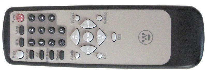
The device shown below is a Westinghouse brand unit that only sends the Sony codes
that the PICAXE is programmed to interpret. Most Sony and multi-brand programmable remote controls will work. It
is possible that some of the buttons will not match what is shown here but is it
a simple matter to modify the code to work with another remote control.
This TV remote control's buttons are used as follows:
Using the Controller
The video shows many of capabilities of the controller.
(right click on the box below and select Play or click HERE)
Hardware
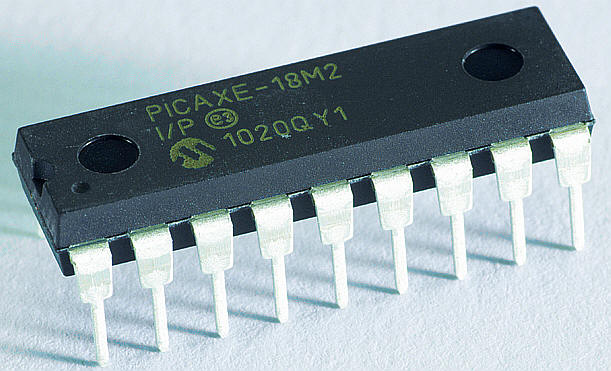
The 18 pin PICAXE 18M2
is the brains behind the controller. This new
member of the PICAXE family is
an extremely capable chip that is well suited to the demands of this project.
The "brawn" comes from a single chip, the L298N H-Bridge.
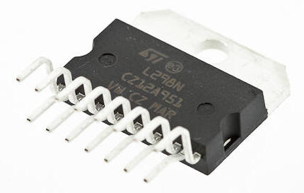
This 15 pin device is responsible for controlling the direction of travel and the speed of the train. It is called an "H-Bridge" due to the fact that such devices are frequently drawn in a schematic with four transistors in an "H" pattern. I like to think of an H-bridge as a solid state double pole double throw switch. As you may know a DPDT switch can be wired so that it delivers power to a train with one polarity setting in one position and with the opposite polarity in its other position. When DC motors have their polarity reversed their direction of rotation is reversed as well.
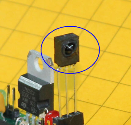
The infrared codes from the hand held remote control are received by a small chip, the Sharp GP1UX511QS. Its small, boxy case and three leads belie its complexity. Inside is a sophisticated circuit that receives the 38 KHz infrared data stream from the TV remote control and filters it into a series of pulses that are easily interpreted by the PICAXE.
Other components include indicator LEDs, a voltage regulator and assorted resistors, capacitors and diodes. All in all it is a straight forward circuit that works very well with loads of up to 3 amps. DC power is supplied by any filtered power supply providing 12-24 volts. I have had great success using old laptop power supplies for this and other projects. Be sure to use an appropriate heat sink on the L298N if current is likely to exceed 1 amp.

How It Works
The PICAXE is programmed through pins 2 and 3 which are
connected to the computer's serial port (or to a USB to serial adapter).
Resistors R1 and R2 are all that is needed to connect your computer to the PICAXE for
programming.
Infrared pulses are generated by pressing a key on the TV remote control. These are received by the IR receiver IC and sent to the PICAXE through pin 8.
All of the power control is done with pins 6, 11 and 9 on the PICAXE. These pins control the output of the L298N H-Bridge. The L298N is designed to operate two separate motors each drawing up to 2 amps. In this application we are only controlling one motor so its control & output pins have been wired in parallel so that one motor can be supplied with up to 3 amps of current. When the PICAXE's pin 6 is high and pin 11 is low the motor is set to rotate in one direction. When pin 6 is low and pin 11 is high it rotates in the other direction. LEDs D2 and D4 light to show you which direction the L298N is set to.
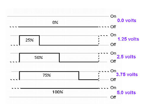
When the microprocessor needs to change the speed of the motor it sends a series of pulses, called Pulse Width Modulation, to the enable pins on the “H-bridge”. This spins the motor at full speed if it sees 5 volts and stops the motor if it sees 0 volts. A voltage between 0 and 5 volts gives a speed proportional to the voltage. Microprocessors generally don’t deal well with variable, or analog, voltages. That is where PWM comes in. PWM sends a series of 5 volt pulses to simulate a variable voltage. For example, if it sends pulses that are on ½ of the time and off ½ of the time the pin appears to have half of the supply voltage or 2.5 volts on it. Sending pulses that are on 25% of the time and off 75% of the time looks like 1.25 volts and so on. (see graphic).
Parts
The parts that are used to build the controller include:
PICAXE 18M2
18 pin socket
circuit board
L298N H-Bridge
7805 voltage regulator
4 @ 2 amp Schottky diodes or 1N4001 silicon diodes
3 @ 0.1 mfd bypass capacitors
4.7 mf tantalum capacitor
3 @ 5mm LEDs, red, green, amber
3 @ 3mm LEDs, blue, green, amber
6 @ 470 ohm resistors
10K resistor
22K resistor
852-GP1UX511QS - Sharp Infrared Receiver
3 pin header for programming
2 @ 2 pin headers for power to track & DC power in
heat sink for L298N
fuse or polyfuse - 3 amps
TV remote control that can generate Sony codes
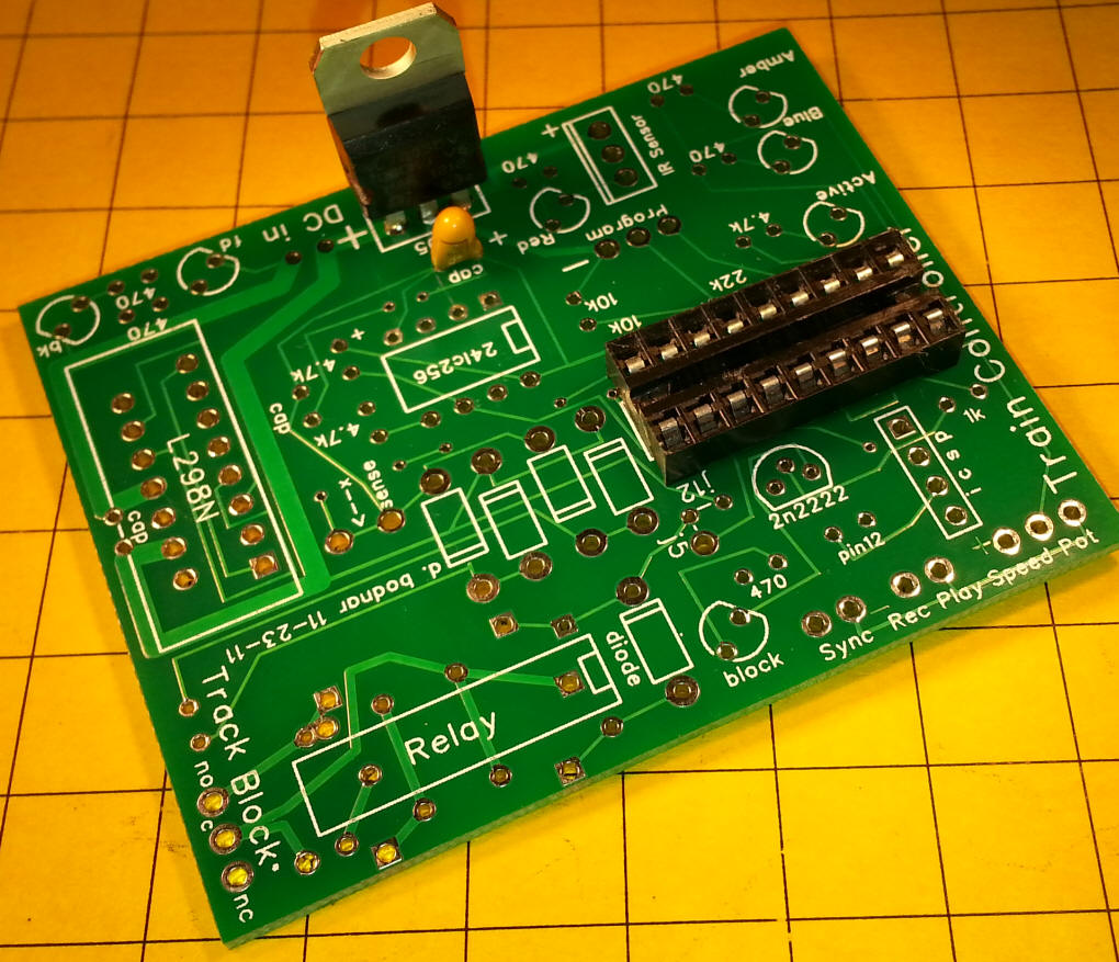
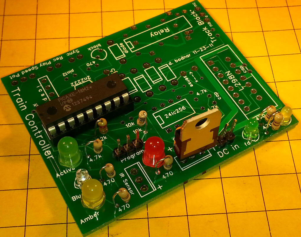
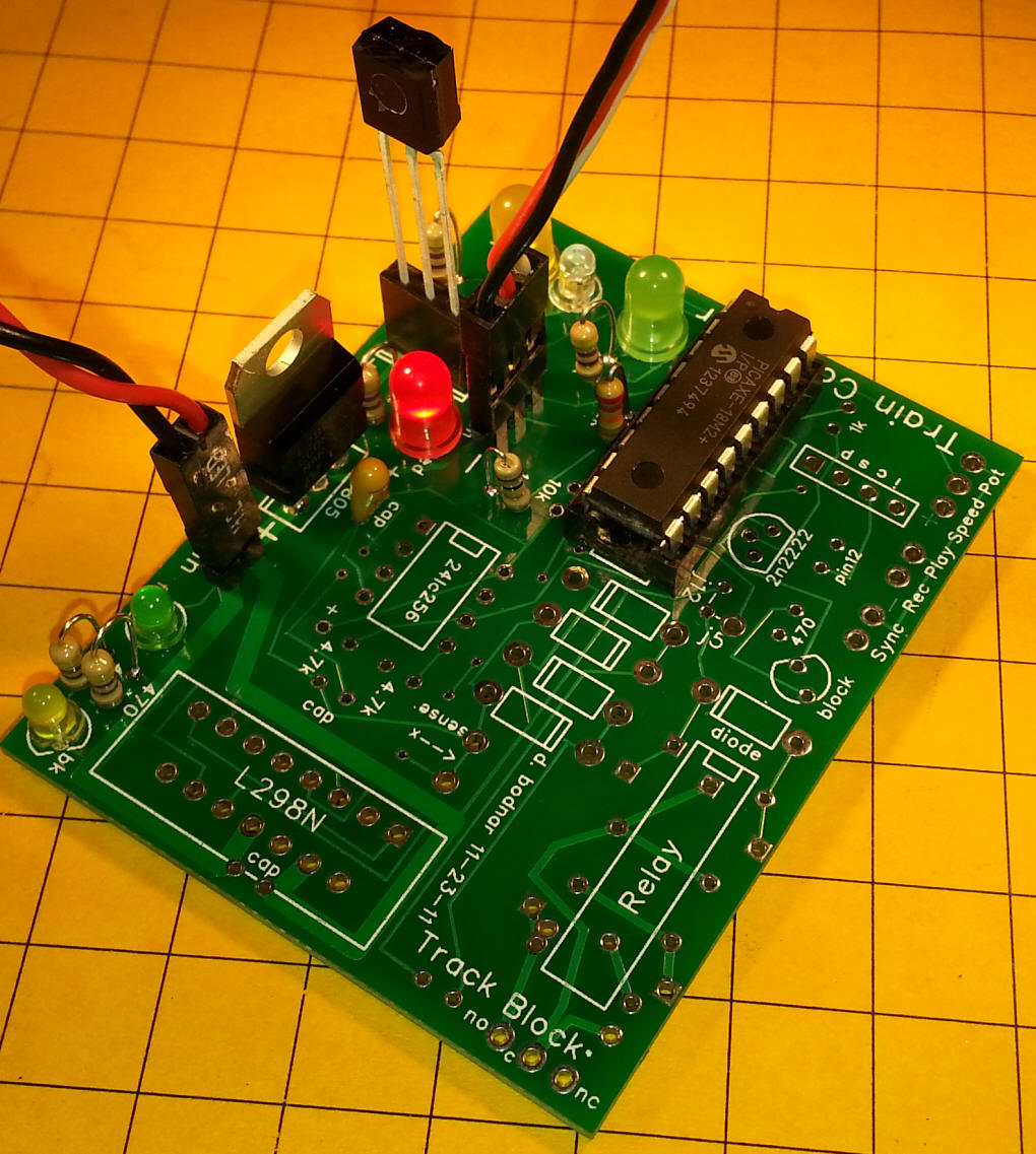
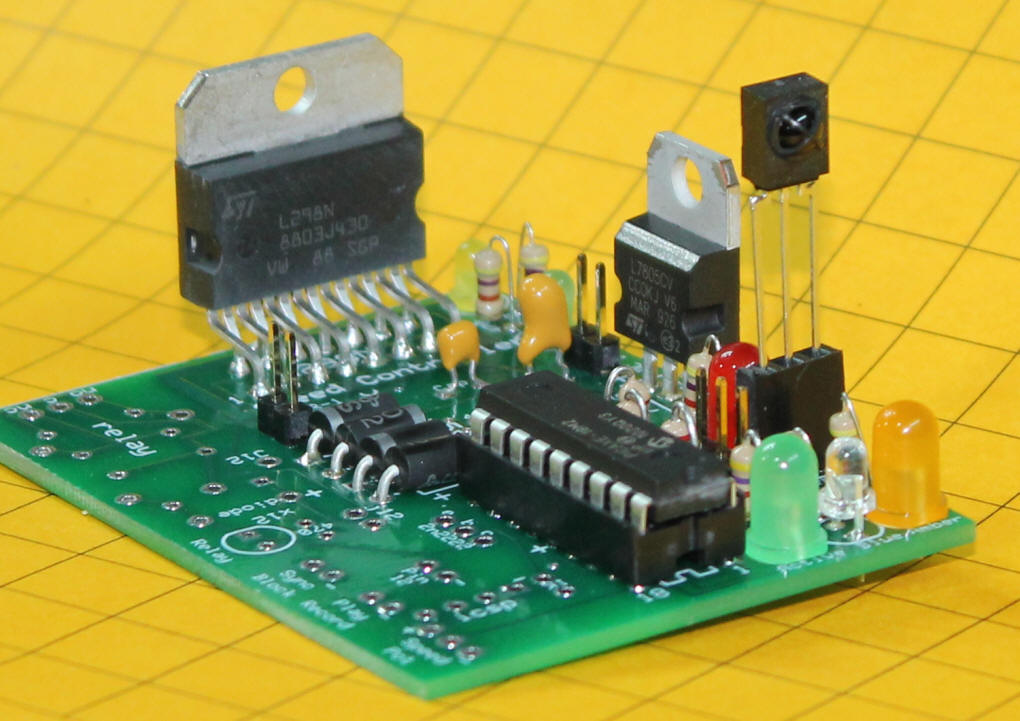
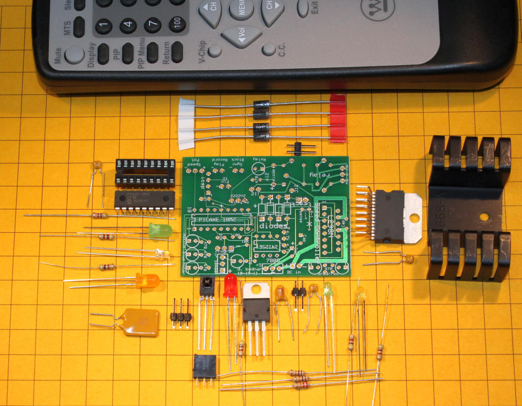
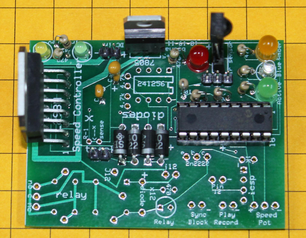
This photo shows the parts arranged near their intended location on the circuit board.
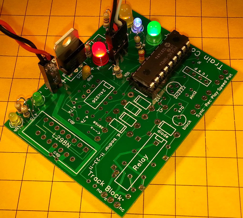
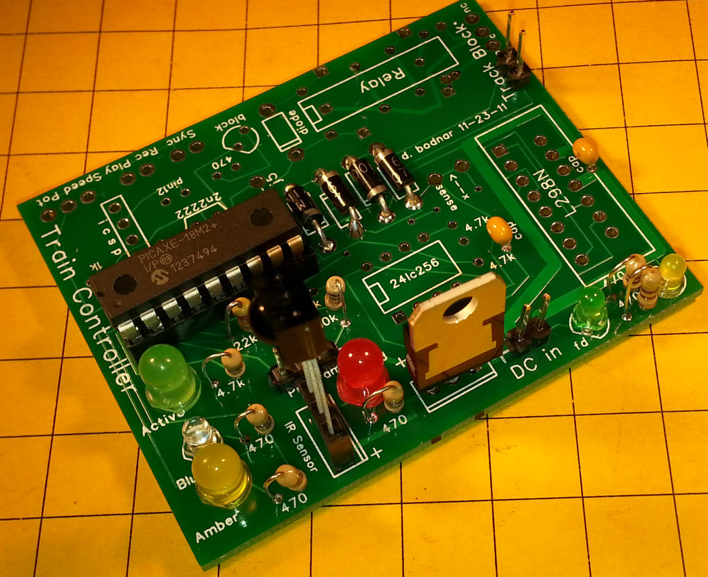
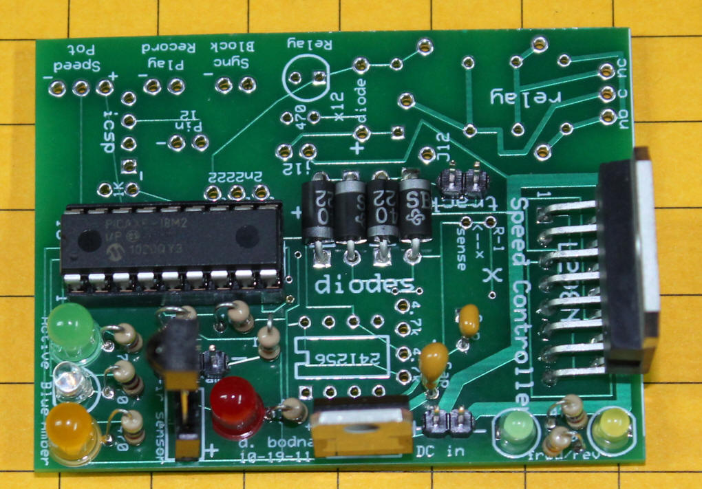
These two photos show the completed board.
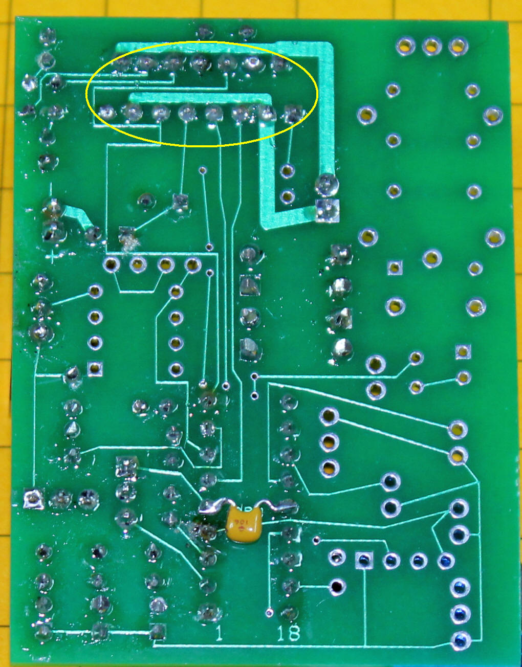
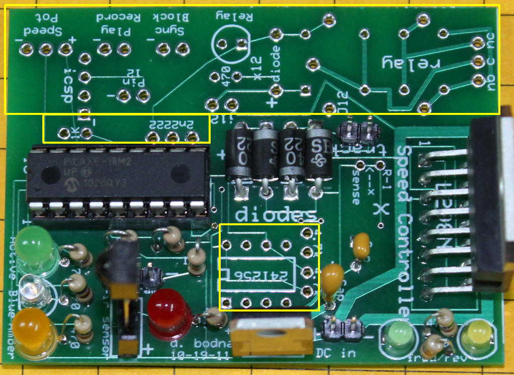
The Rest of the Board
You may be wondering about the unused areas on the board, those
shown boxed in yellow below. These areas are for additional
components that are used in the next phase of this project where the
controller is used to record and play back a train's movements.
They will be utilized and fully described in the next article.
Stay tuned!
| Construction and Step-by-Step Testing Although this circuit can be constructed on a number of different prototyping circuit boards the easiest way to make it is on a custom circuit board that was designed and fabricated to do exactly what is shown in the schematic.
Start by installing the voltage regulator, tantalum filter capacitor and the PICAXE socket. The 7805 voltage regulator must be installed as shown in the photos. The tantalum filter capacitor has a small + on it and must be oriented so that the + lead goes into the hole marked with a +. Be careful as there is another set of holes nearby that are also marked "Cap" but they are for another capacitor that will be installed later.
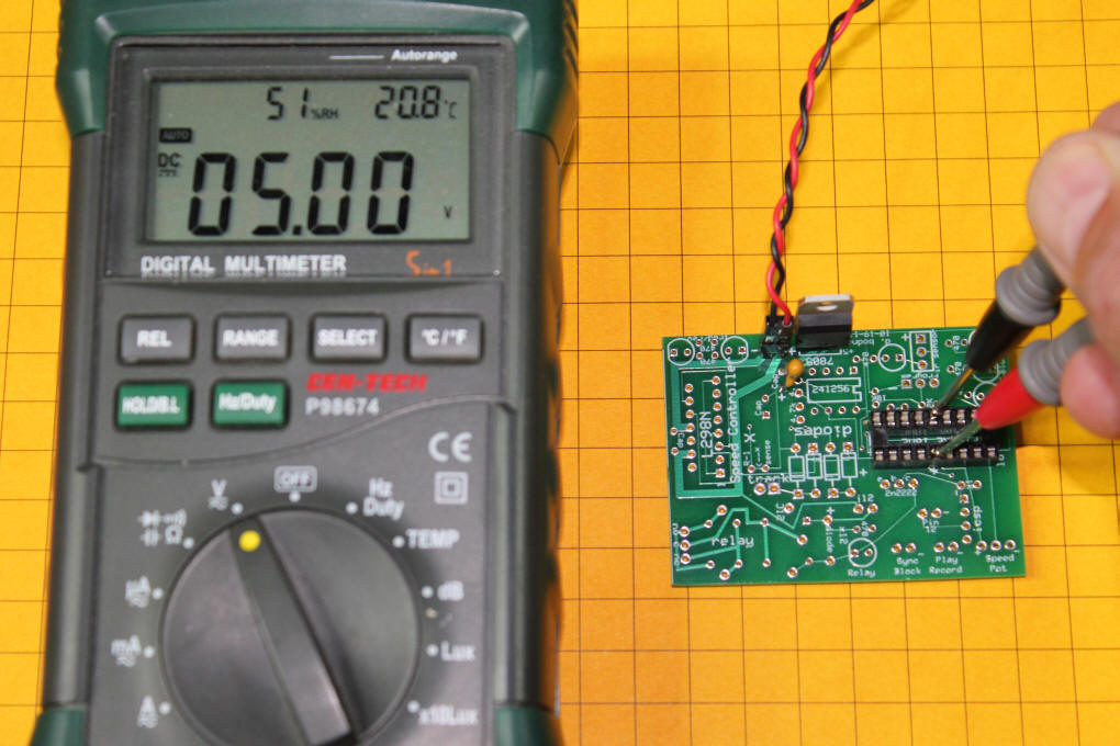
Once this is complete you can apply power and check pins 5 and 14 on the socket for +5 volts. Be sure that you connect the power leads correctly to the pins labeled "DC in". The pin marked "+" gets the positive voltage and the pin marked "-" gets ground (negative). Set your volt meter to the DC scale and test between pin 5, negative, and pin 14, positive. The meter should show 5 volts plus or minus a tenth of a volt.
5 Volt Test Video
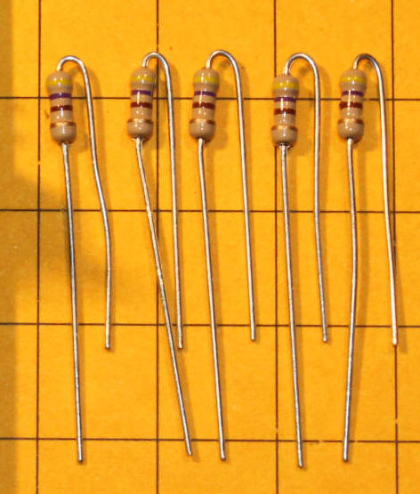
LEDs and Resistors
Insert the six LEDs into their locations on the board. LEDs are polarity sensitive and must be installed properly. The notch on the LED is the cathode, or negative lead. It is marked on the board showing the flat side of the LED. The cathode lead is also the shorter of the two LED leads. Push each LED close to the board and solder from the back. Trim off the leads after soldering. Install the 10K and 22K resistors that are part of the programming circuit. At this point the PICAXE can be installed and tested with the programming software. Please be sure to insert the PICAXE chip so that all of its pins go squarely into the socket (none are bent underneath) and that the notch on the end of the PICAXE is located close to the edge of the board. The three pin connector just above the red LED is used for programming. The negative lead of the programming connector is to the right and is marked with a small "-" sign.
Here the matching three pin plug has been inserted.
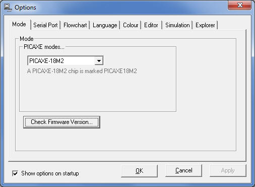
Start the PICAXE programming editor. This free program is available for download at http://www.picaxe.com/Software . When the program starts it normally displays a set of options as shown here. If this is not shown click on View from the main screen then Options. Make sure that the PICAXE mode is set to PICAXE-18M2.
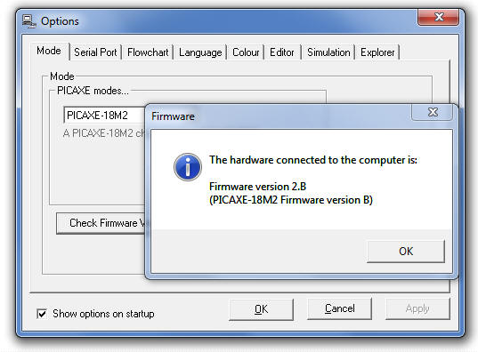
Click on "Check Firmware Version" to test your circuit. You should see a message similar to the one shown below. If it is not displayed check your serial port settings under the "Serial Port" tab and try again. When you see the message below displayed the PICAXE and the software are "talking" and the microcontroller can be programmed. If you have difficulty reread the serial connection sections in the PICAXE Getting Started Manual. There is also information on serial programming problems on the PICAXE forums at http://www.picaxeforum.co.uk/ .
To test the LEDs load the LED_TEST.BAS program into the program editor, connect the board to the programming cable and power. Click the "Program" button at the top of the screen. Once the program has been downloaded to the PICAXE you should see the amber, blue, green, red, small green and small amber LEDs flash in sequence. If any of the LEDs does not light check your solder joints and the orientation of the LEDs in the board. If they are inserted backwards they will not light.
LED_TEST.BAS Program:
LED Test Video
Infrared Sensor: Solder its leads leaving the sensor as far above the board as possible. If desired the sensor can be moved closer to the board later on but it is better to leave the leads long for testing. If you are planning on putting the finished unit into project box you may want to connect the IR sensor's leads on wires so that it can be placed on the outside of the box. In this photo the sensor is plugged into a 3 pin female header so that it can be removed and repositioned as needed.
Here the board is almost done. Just the H-Bridge is missing.
To test the sensor load the IR_TEST.BAS program into the editor, connect the board to the programming cable and power. Click the "Program" button to load the software. When programming is done click OK to get rid of the "Programming successful" box. Click the PICAXE tab then click "Terminal...". The terminal screen will appear. Make sure that 4800 is selected as the Baud Rate and that the programming cable is still attached. Aim the TV remote towards the sensor and press a button. You should see its corresponding code displayed on the terminal. Note that you can skip this step if you insert the directive (#Terminal 4800) that is shown in the IR_TEST.BAS program as the terminal screen will automatically be displayed.
IR_TEST.BAS Program:
IR Codes Test Video This is also a good time to test your TV remote control, especially if it is not the same as the one used here. This table shows the buttons that are used and the codes they produce:
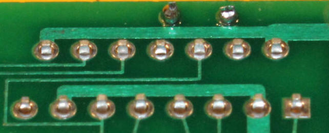
If you find that any of the codes that your remote control generates are different than those above be sure to make appropriate adjustments in the program. Other Parts: Install and solder the two pin connector labeled "track". Insert the L298N's fifteen leads into the circuit board. It may take some gentle bending of the leads to get them all in. They do not need to go very far through the holes, just enough to get a good solder joint. Here the L298N's leads are shown from the back of the board, before soldering.
This photo shows the L298N after its pins have been soldered.
The last small capacitor goes on the back of the board between pins 5 and 14 on the PICAXE. Cut its leads before inserting and soldering to the board. The board is now nearly complete. Add the heat sink to the L298N if you will be using trains that draw more than 1 amp. For smaller trains that draw little current it may not be needed. In addition you should add a two or three amp fuse to the power input connection. You can also use a polyfuse that automatically resets after an over current issue is cleared. |
|||||||||||||||||||||||||||||||||||||
|
Simple test program (fast / slow / fwd / back)
'd. bodnar 6-21-2011
Motor Test Video
Latest and Greatest Control Program I hope to update and expand the capabilities of the controller by modifying the software as I and other users of the controller make changes. Check back often for the latest version.
Use on-board trains
Going Further The point-to-point controller could be redesigned so that reed switches along the track were activated by a magnet on the train so that the train slows and stops at a station and then continues on its way. Reed switches could also be employed to reverse the train at the end of the track. Up to four of the extra pins could easily be connected to one of the inexpensive MP3 sound units described here: http://www.trainelectronics.com/USB_Sound_4/index.htm. The program could be modified to sound a bell, whistle or horn when the train stops, starts or slows down. Even though the sound would not emanate from within the train or trolley a speaker could be hidden within the layout to give the illusion that it was.
A Kit is Available
Programming Cable
As usual, please let me know how I can help. dave@davebodnar.com |