A Four Sound USB Sound Card & the PCC Trolley
d. bodnar 02-14-2011
About a year ago I reviewed "A Very Capable MP3 Sound System" and found it, at less than $10.00, to be a cost effective way to add sound to a train, building or animation. The folks at Electronics123 who developed and import that unit are not resting on their laurels as they now have a new sound system with significantly more capability that only costs a few dollars more.
The new unit builds on the capabilities of the original unit as it:
is also easy to use
plugs directly into a computer's USB port for sound downloads
utilizes another type of sound format called Wave or wav files
costs about $16.00
can record up to 300 seconds of sound
accommodates four separate triggers that can each call up a different sound
can easily be triggered by switches or Radio Control systems
has an output jack for a direct connection to external monaural speakers
The differences between the two boards are highlighted in the list. The two most significant differences are the recording length, as much as 5 minutes, and the fact that you have four individual triggers that can each call up a different sound file. The price is higher but the added capability certainly goes a long way towards justifying the increase!
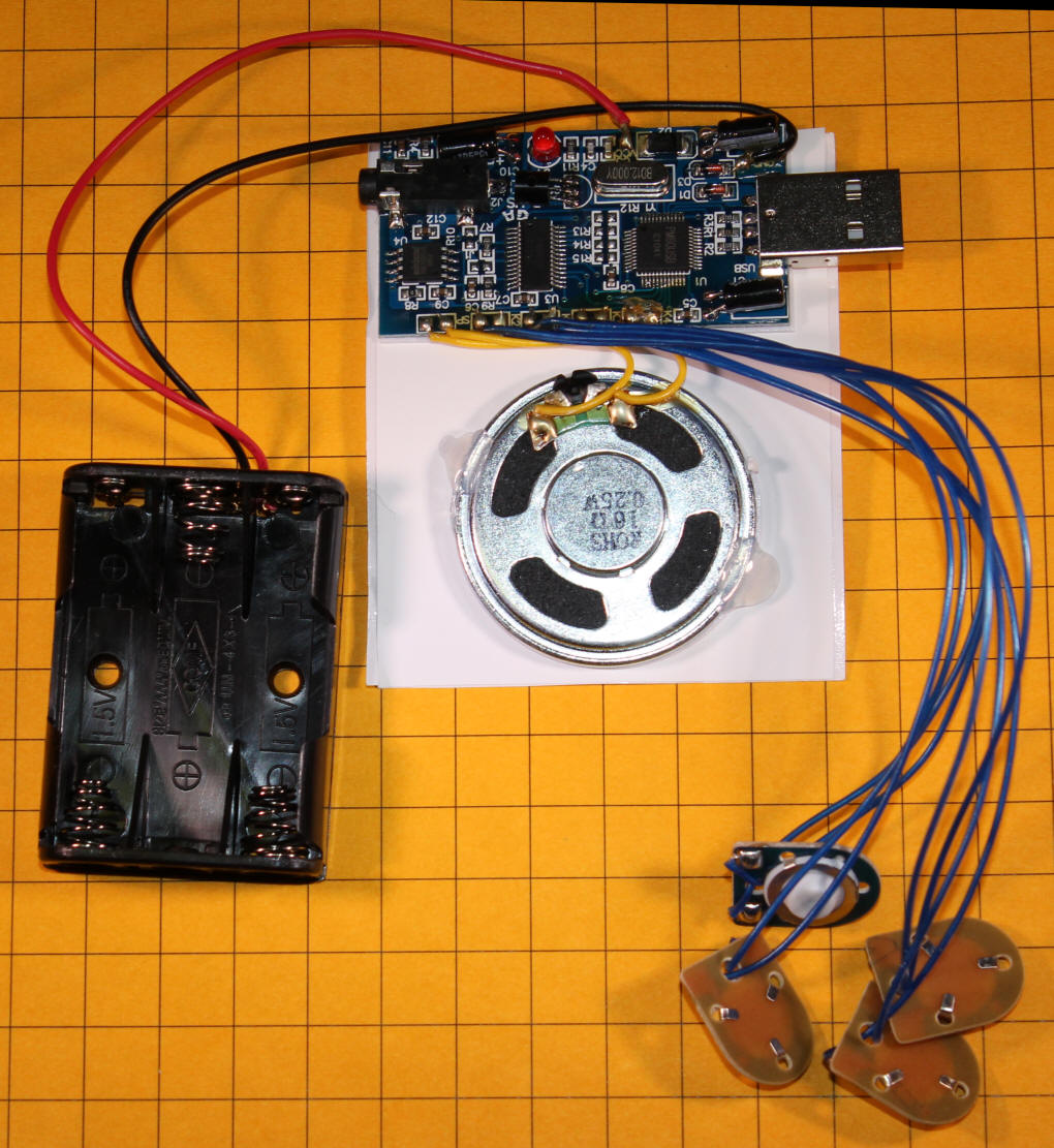
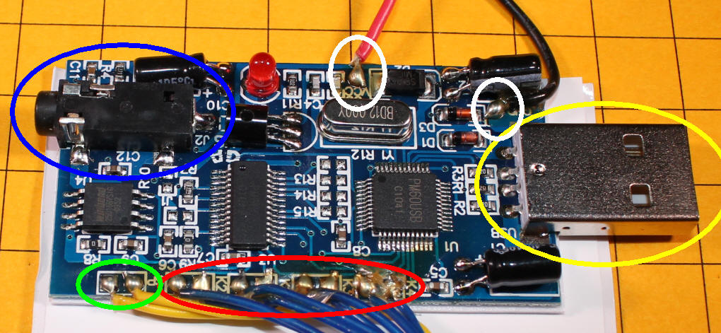
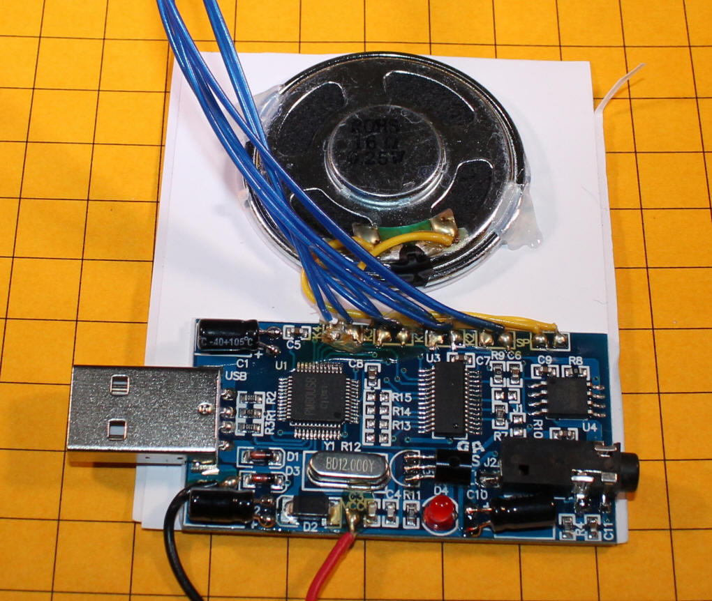
Important Parts
The USB connector that plugs into the computer is circled in yellow.
The jack for connecting to external speakers is circled in blue.
Power is supplied by three AAA cells which provide 3.6 volts.
The power connections are circled in white. No more than 5 volts DC should be used.
The speaker connections are circled in green.
The four triggers are circled in red. There are two solder pads per trigger. The ones to the left are ground and those to the right are the trigger connections.
It is also important to note that the on-board amplification has been improved so that the factory supplied speaker is much louder than the one on the original board. For many applications it will be sufficient where the other board really needed an external amplifier to be heard outside.
Software
The software that is used to add sounds to the board is a bit more complex than the software that goes with the single sound board but part of that is because of the increased capability of the new unit. The software can be downloaded here:
http://www.electronics123.com/s.nl/it.A/id.3041/.f
A description of how to use the software is on Electronic 123's web page
http://www.electronics123.net/amazon/datasheet/usb5msoftwaremanual.pdf
The software comes in a compressed format called a TAR file. You need to download a free TAR extracting program to uncompress the installation software. This is explained on the Electronics 123 web page. If you have any trouble with this process drop me an email and I'll see if I can help.
Basic Settings
Here are the setting that I use when programming the sound unit.
Interface: KEY - the other options under Interface are not used with this board.
Key: Since there are four activation keys you can use K1, K2, K3 and K4. Ignore the others.
Trigger Function: Most of us will use the first option "One Shot Re-Triggerable" which means that the sound will play only once when the key is pressed - if you press the key again it will play again.
Voice Output: To use the speaker the setting should be "PWM Direct Drive". If you are going to use an external amplified speaker set it to "DAC for Ext. AMP". After some experimenting I found that I got the best audio for both a directly connected speaker and an external speaker on the "DAC for Ext. AMP" setting. You may want to experiment with both to see what is best for your sound files.
Volume: I always use Normal as the higher volume settings tend to distort the sound.
To select the sound that will play when the first key is activated, make sure that K1 is showing in the Key column. Click the small down arrow to the right side of the file name column (circled in yellow) and select New Wave
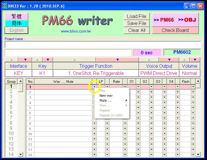
Navigate to the Wav file you want to use and select Open. For a quick test there are a number of sample files in the DemoWav directory. You can add additional files to K1 by repeating these steps in the spaces below the one you used for the first file. Each sound will be played in sequence when K1 is pressed.
Above the "Voice Output" lable there is a box that shows the number of seconds of sound that you have loaded. It increases each time a new sound file is added. This total cannot exceed the capacity of the sound unit which is 300 seconds.
Other Software Options
Once a file has been selected you will see that the default sample rate is 8K - that rate gives a fair quality of sound but it can be increased, at the expense of how many seconds of sound that you can store, by changing the rate to 16K or 20K. The number of seconds of memory taken up by a sound is increased proportionately when a higher sample rate is chosen. For example a 16K sample rate takes twice the memory as does an 8K rate.
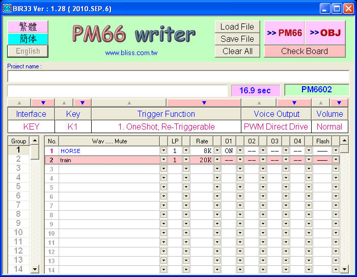
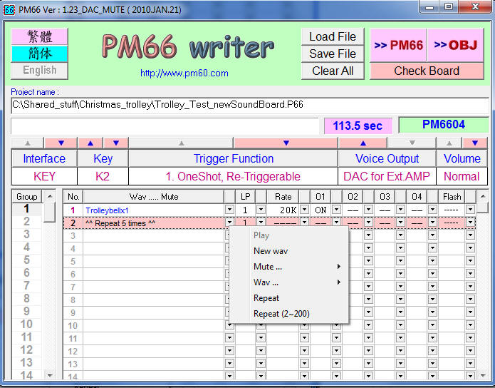
There are two other options that are available when setting up sound for a key. In the graphic below the program is set to "Repeat" the sound over and over again. It will play until power is removed or another key is pressed.
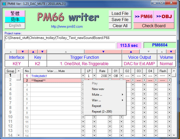
The other option will repeat a sound some number of times from 2 to 200. This is a nice way to use one sound file to create a 2 or 3 or 4 bell ring sequence without rerecording the sound.
The column under "O1" determines if the LED on the board will flash when a sound is playing. The Flash column determines the flash rate. For most applications these settings can be ignored.
There is a video that gives the basics of using the software here: http://www.electronics123.com/s.nl/it.A/id.3041/.f
Wave Files
The original board used MP3 files and this one uses WAV files. Files of both types can be found on the Internet and the can be converted from one to the other with programs such as Audacity and the program that Electronics 123 recommends, GoldWavev.5 Note that the GoldWave download is for an evaluation copy that can be used a limited number of times. Audacity is free for unlimited use. I went into a great deal of detail about how to use Audacity in an article that I wrote about another sound unit. See:
http://www.trainelectronics.com/MP3_project/
Audacity is a very capable program and certainly worth learning.
This article also shows how you can find sound files on the Internet. Remember that you can use your computer's microphone to record your own sound files using Audacity or any other sound recording program. Just make sure you save the files as WAV so that they can be used with the sound unit.
Use with an External Speaker System
The other USB board required some soldering and other modifications to connect the output directly to external speakers. This new board has an 1/8" phone jack on the board that can be used to connect directly to an external speaker.
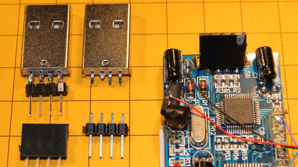
A bit of work is still required if you want to use this device with a standard set of stereo speakers. The plug from most speaker sets looks like the one on the left. There are three distinct sections to the plug. The one on the right is ground, the center is one of the stereo channels and tip on the left end is the other stereo channel.
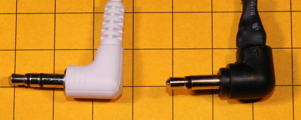
The USB sound device uses a plug like the black one on the right. It only has two sections. The right section is ground and the tip goes to the speaker.
Fortunately Radio Shack sells an adapter http://www.radioshack.com/product/index.jsp?productId=2062469 that is available at most stores. They are also available on eBay: http://cgi.ebay.com/3-5mm-1-8-Mono-Plug-Stereo-Jack-Audio-Adapter-/150559192159?pt=LH_DefaultDomain_0&hash=item230e06f45f
Sound Quality
The sound that can be reproduced with this unit will never match that of a $100 or $200 sound card but it can provide sound that is more than adequate for many of our needs. A few suggestions for getting the best sound include:
Start with a good quality sound file
Use Audacity or some other sound editor to edit your sound files making sure that they are not too quiet or too loud and distorted
Use the 16K or 20K sample rate to get the best sound. Some experimentation may be in order to properly balance sample rate and the number of seconds you need to record. The board is able to provide about 300 seconds of sound at an 8K rate but only about 150 seconds at a 16K rate.
Experiment with the Volume setting in the software. I have not had good luck with volume settings other than "normal" but your sound file may work well at higher volume levels.
Try a better speaker than the one that is included with the sound unit.
Consider using an external set of amplified speakers. The sound is VERY much improved when used with an inexpensive set of computer speakers. This may not be practical when you add sound to a trolley or locomotive but amplified speakers can be made to fit into most box cars and buildings.
Use with the Revolution
This unit works with the Aristo Craft Revolution receiver just as well as the single sound unit. As an added bonus all four of the key inputs on the sound board can be connected so that the Revolution can call up four individual sounds. I soldered a 1,000 ohm resistor to each of the key inputs. Connect the resistors to the solder pads closest to the K1, K2, K3 and K4 labels. The other end of each of these resistors is connected to one of the colored wires on the auxiliary interface cable. The black lead from the Revolution cable is connected to one of the ground pads as shown in the photo. Note that the inputs for the four keys are not in order. The one closest to the speaker connection is K2 followed by K1 then K3 and K4.
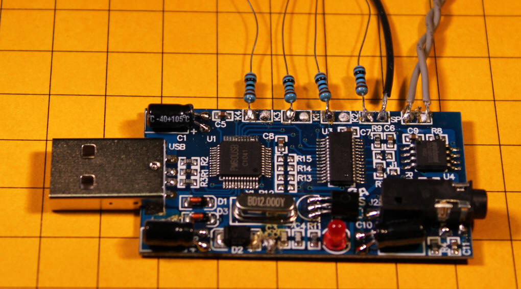
Before soldering to this board take a few minutes to scrape off the layer of glue that is over the solder pads. This glue is similar to rubber cement and will gum up your soldering iron if you don't remove it first.
This diagram shows how the wires are connected to the Revolution and how a power supply can be used to provide 5 volts to the sound unit. The power supply is discussed in the earlier article: http://www.trainelectronics.com/MP3_USB/index.htm
Use with the Aristo Craft PCC Trolley
This sound unit has proven to be a very cost-effective way to add sound to the new Aristo Craft PCC Trolley. It can easily be set up to play a trolley bell and / or boarding announcements or other sounds.
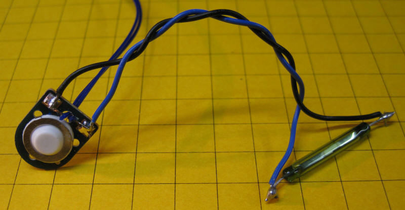
I have added one of these boards to my PCC Trolley and have three of the key inputs wired to reed switches under the trolley. One of the reed switches is on the left side of the trolley, one is on the right and one is in the center. That way I can trigger three different sounds by placing magnets on different parts of the track.
You can either wire the reed switches to the existing switches or you can remove the push button switches and wire the reed switches directly to the sound board as I have done.
Installation in the PCC Trolley
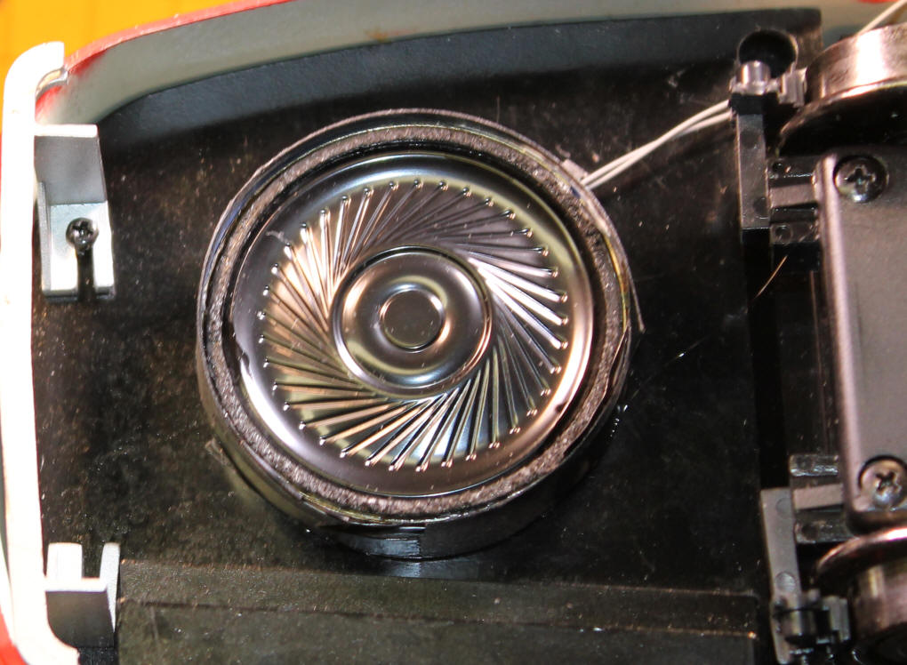
I experimented with a few speakers that I had in my junk box and I was surprised to find that I could not find one that gave better sound than the small speaker that came with the sound unit. It provides very acceptable sound reproduction at a good volume level. I am sure that other speakers are available that can improve on this but I would suggest giving the small speaker a try, especially if you enclose it in a small baffle as shown below. To make the baffle I simply wrapped a 1/2" x 12" strip of heavy black paper around the speaker and glued it in place. As you can see the speaker fits nicely in the space under the front set of doors.
Next I had to decide where to mount the sound board. There is plenty of room at the rear of the frame but I didn't want to run wires the whole length of the car to get to the speaker so I opted to see if I could get the sound board into the space in the center of the trolley that is normally used for a Revolution receiver or DCC board. If you are using one of these devices you will have to try an alternate mounting area like the end of the car.
Track power is available in the compartment in the trolley. That would allow me to get power for the 5 volt power supply that is described above. Rather than build up a new power supply I did some testing and found that two of the five pins in the header inside of the compartment were sources of 5 volts DC, just what I needed!
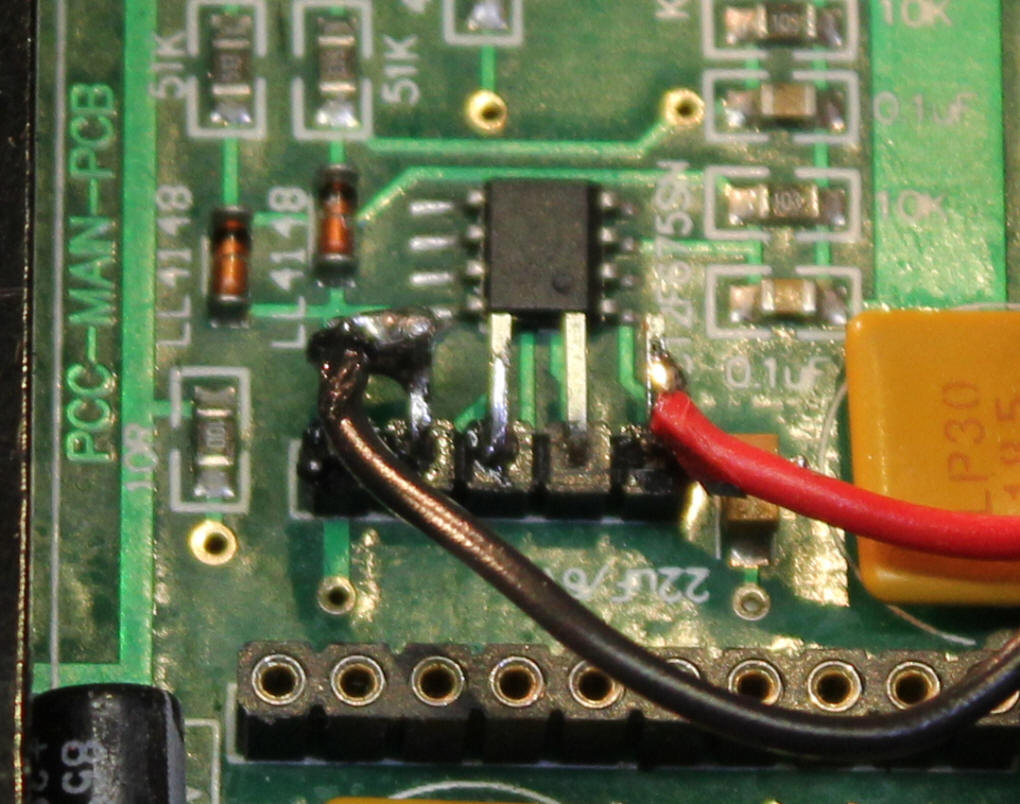
In the photo below you can see that the pin on the right has a red wire soldered to it to pick up +5 volts. The pin all of the way to the left is ground. You will note that I soldered the black wire to both the ground pin and the one next to it. That accomplishes the same thing as leaving the brake light jumper on those two pins. As you can see in this photo it was also necessary to bend the five pins over so that they are nearly parallel to the board beneath them. This provides space for the sound card in this compartment.
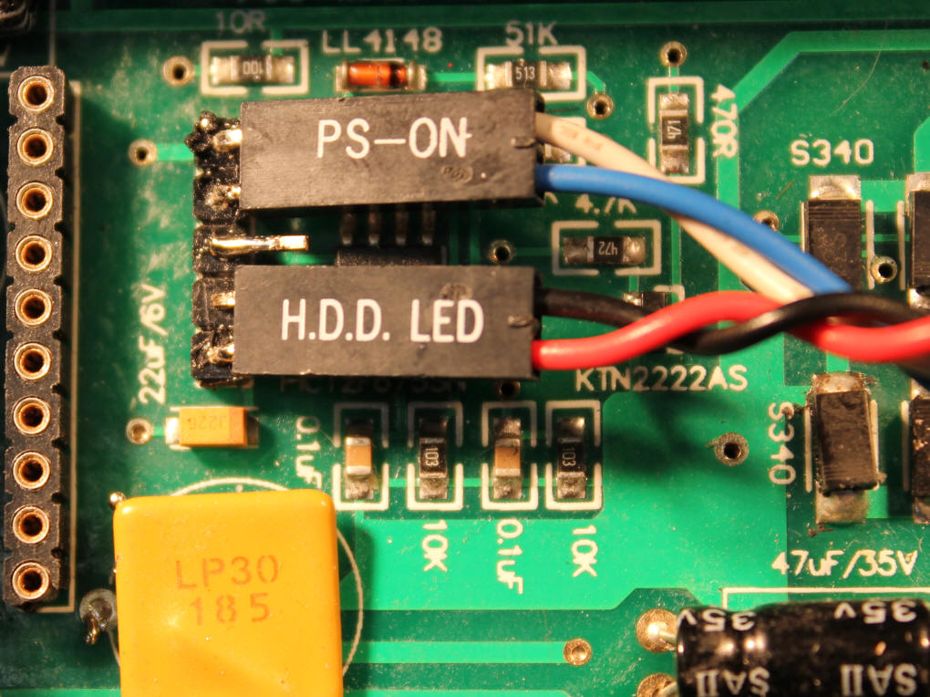
For those of you who might be a bit reluctant to solder directly to the Trolley's circuit board you can use a pair of motherboard plugs from an old desktop computer. Remember those wires inside of computers that connected to the hard drive LED, speaker and such? They are a perfect fit for the pins in the trolley. In this photo you see a blue / white plug that is going to the ground and brake light pins and a black / red plug that is going to the +5 volt connection. In this case you would connect the blue and white wires together and use only the red wire from the other plug. No soldering to the pins!
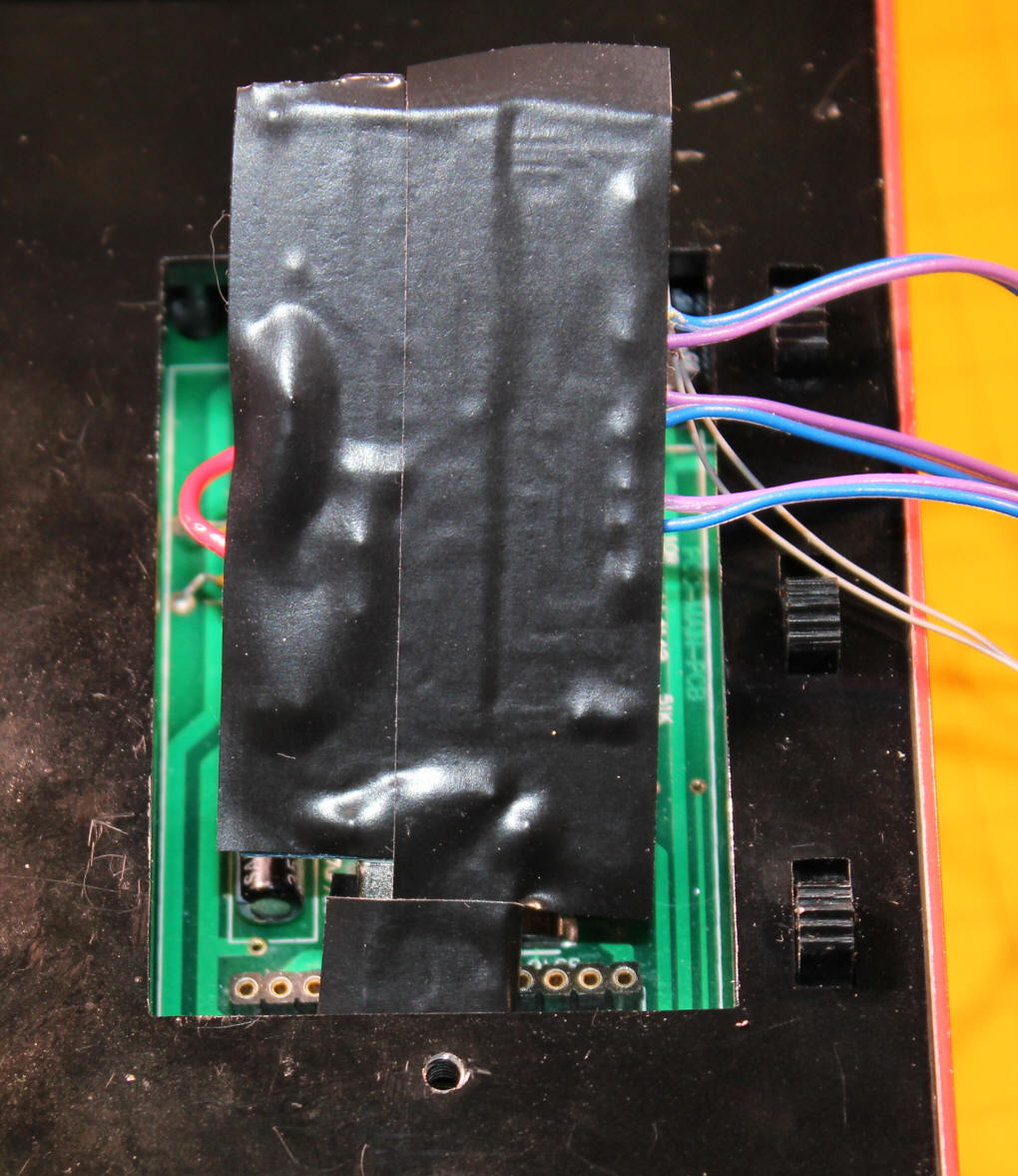
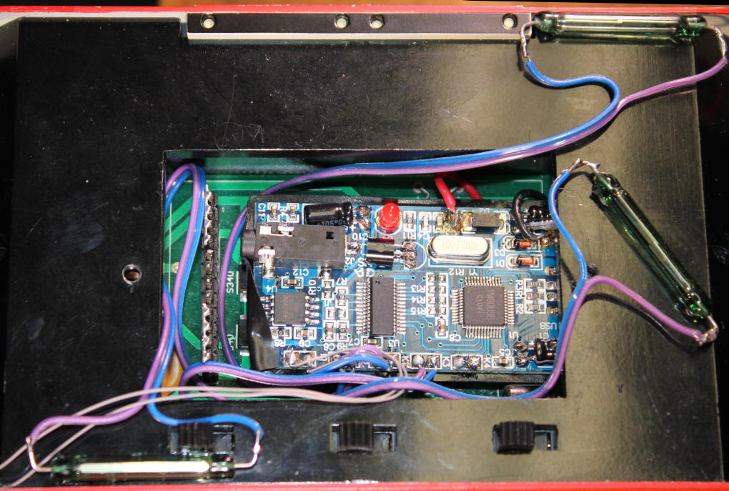
Before trying to insert the sound board I completely covered its bottom with a thick layer of electrical tape to guard against short circuits. In this photo you can also see the three pairs of wires that will go to the three reed switches and the wires that go to the speaker.
To insert the board you have to temporarily remove the jumper that is shown on the left. It takes a bit of work but the USB plug end of the sound board will just fit above the plastic connectors that are under the trolley's frame. Once the board is in position you can reinstall the jumper.
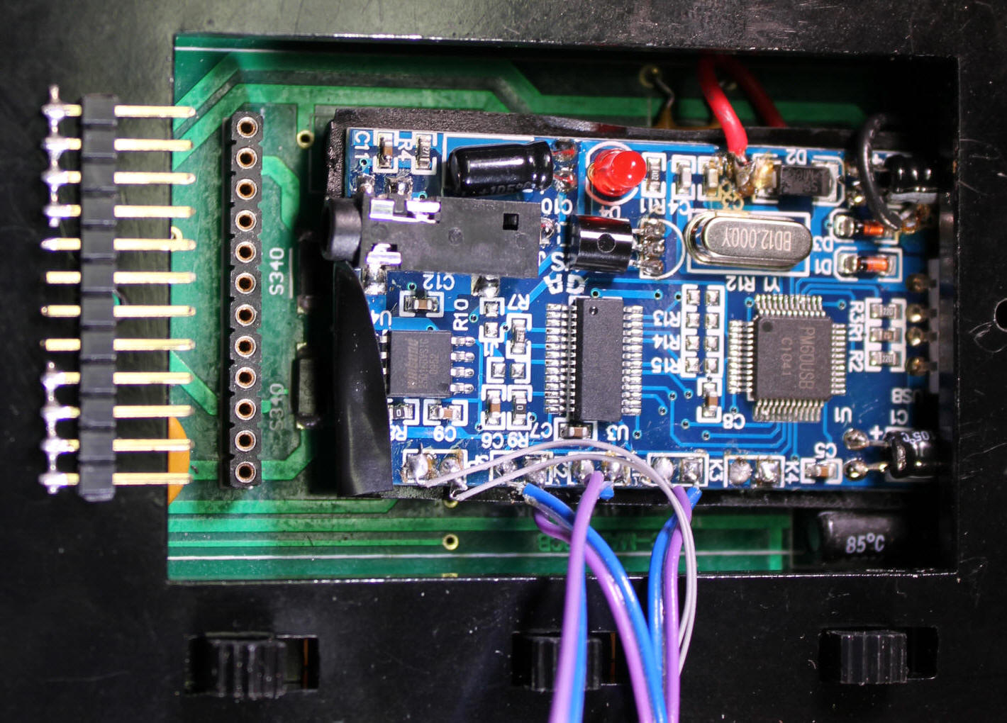
Here is the completed installation with three reed switches. One on the left side of the trolley, one in the center and one on the right side. Because the trolley's frame is high I had to mount the magnets that activate them fairly high off of the track. If you want to get the reed switches closer to the track you could mount them on the trucks of the trolley.
Another Option if it Will Not Fit!
If you find that the USB connector on the end of the sound board gets in the way and prevents you from mounting the board where you want it there is another option. If you have a "solder sucker" or solder braid and some good soldering skills you can remove the USB connector from the sound card and replace it with a smaller 4 position connector as shown here. I replaced the USB plug with a small female connector and put a matching 4 pin plug on the connector that I removed.
Conclusion
I think that you will find a number of ways to use this new sound board on your railroad. It does a very good job of bringing sounds that you find on the Internet or that you create yourself to your locomotives and buildings. Please let me know if I can help you in making it work for you.