PICAXE Model Railroad Speed Controller
Train Activity Recorder
d. bodnar
revised 06-03-14
Click here for Video
|
Introduction The modifications to the original circuit that are shown here do exactly that: turn the device into a record / playback unit that does something that is rather unique in model railroading. You can run the train in a complex pattern composed of forward movements, backwards movements, stops, slow speed running, higher speed running, etc and have it all recorded so that it can be played back again and again. Ten or more minutes of running can be recorded and stored indefinitely for playback. Repeatability is realized by utilizing an isolated section of track that acts as a "sync" block. Power to this block is controlled by a relay in the circuit. By producing a set of train motions that start and stop in this block a very reproducible sequence of movements can be realized. An optional "Start" button can be used to initiate each playback session. This is ideal for a public train display where viewers push a button to start a train. As I mentioned in the first article I plan on installing and using this controller at the Children's Hospital layout that I help to maintain. This unit also makes an ideal point-to-point controller for a trolley or small train. By adding diodes at each end of the track two sync points are created that can provide a very repeatable sequence of movements with an almost unlimited number of station stops, pauses, reverses, etc. |
|
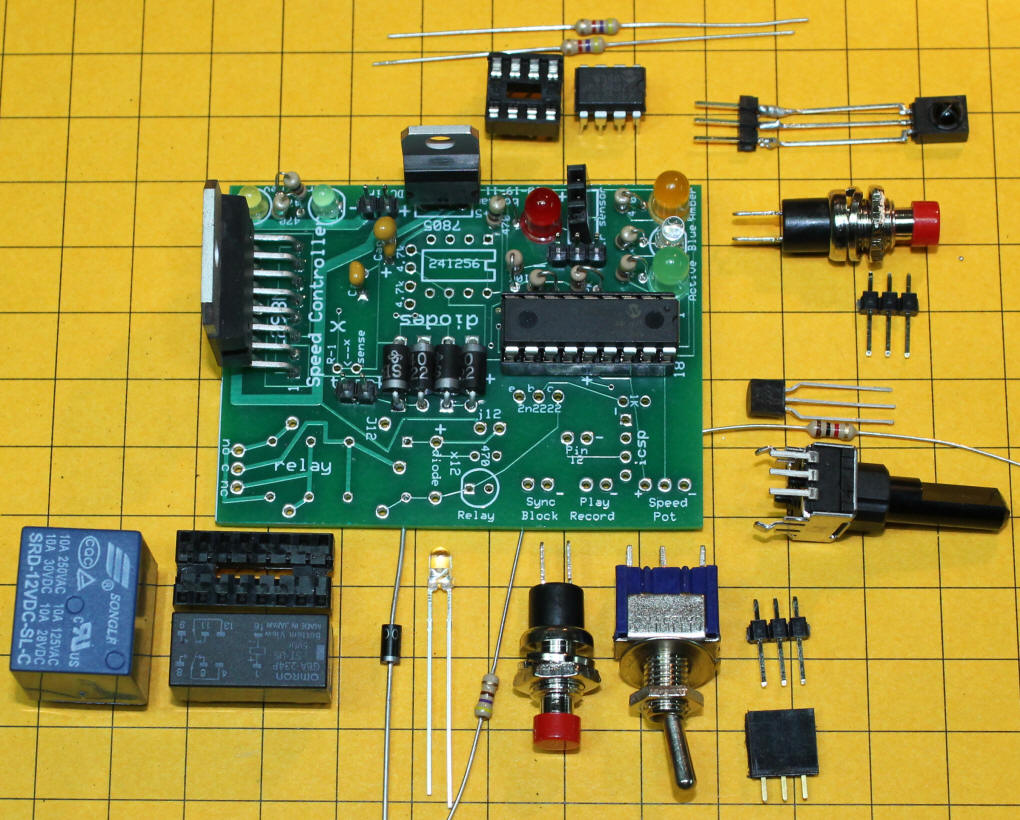
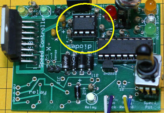
| Activity Recorder Modification The original circuit can be turned into a digital train travel recording unit with some hardware modifications and new software. To use the controller in this way two switches, a potentiometer, a relay, an external memory IC and a few other simple parts are added to the circuit. This photo shows the board without the recorder modification. The highlighted areas that were not used in the first project will accommodate the additional parts that are needed to make the recorder.
The extra components include:
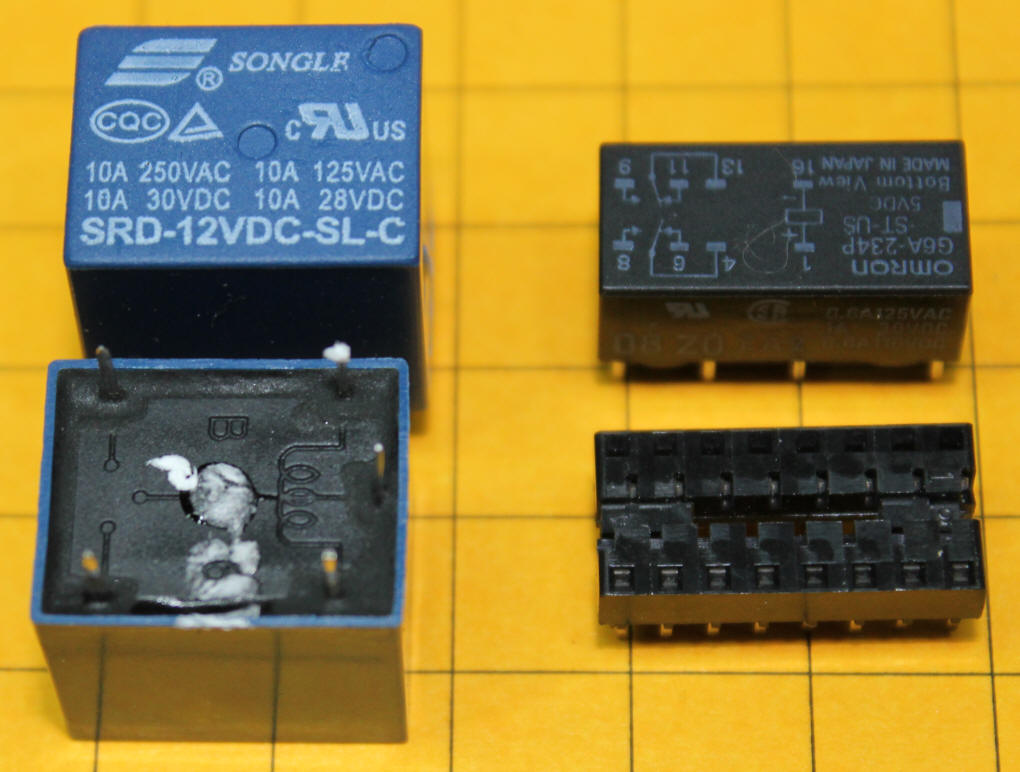
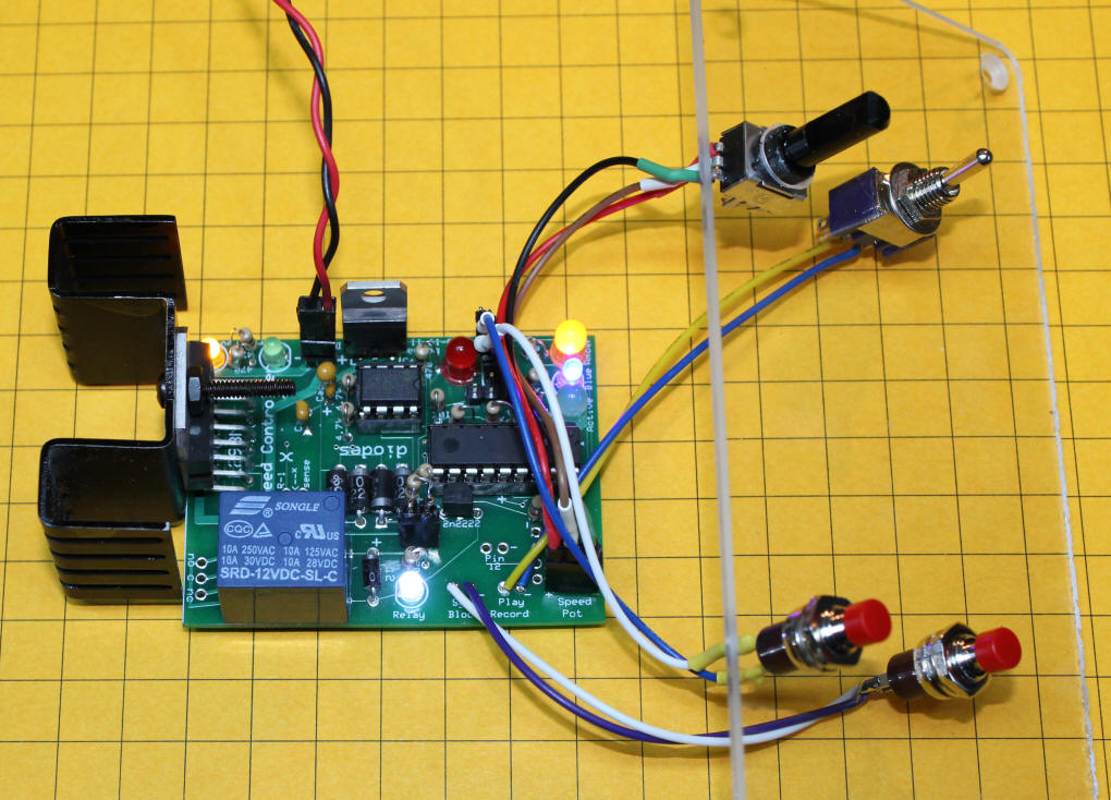
The photo at the top of the article shows the completed board with the blue 12 volt relay that is shown above. The black relay is a 5 volt unit that will fit into a 16 pin IC socket. Wiring the Board You can use either a DIP relay or a SPDT relay with this board. 5 volt and 12 volt relays can be used. If a 5 volt DIP relay is installed no modifications to the board are necessary. A 12 volt relay requires a few changes. You need to cut one trace on the board, the one that delivers 5 volts to the relay pins, and install two jumpers to supply it with 12 volts. If you are planning on using a higher voltage power supply than the rating of the relay you can install a current limiting resistor as explained below. The blue relay on the left is a SPDT 12 volt unit. As you can see from the photo its coil is connected to two pins and the SPDT contacts to the other three. The coil on the black DIP relay is connected to the two pins on the far right and the DPDT contacts are to the left. The circuit board wires the two sets of SPDT contacts on the black relay in parallel to allow it to handle more current.
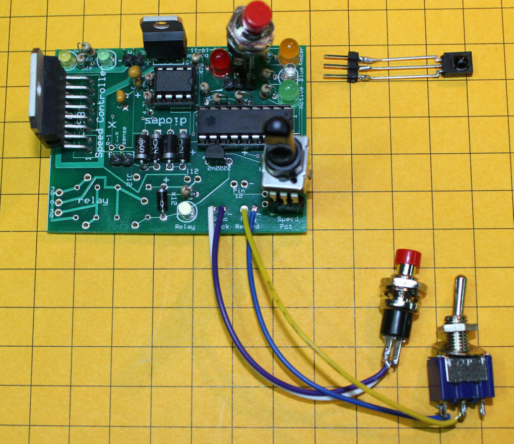
This photo shows the board with everything but the relay installed. The IR sensor has been removed and a push button installed in its place. The pushbutton switch connects to the two contacts on the IR sensor socket that are closest to the PICAXE chip. The contact closest to the edge of the board is not used when the switch is installed. The two switches at the bottom are the Play/Record toggle switch and the Sync block push button switch. They have been installed on short lengths of wire so that they can be mounted externally. The other switch and the pot will be wired in a similar manner.
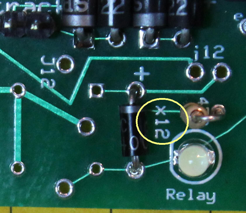
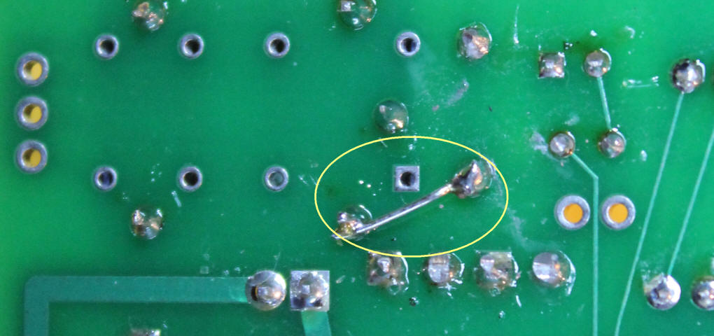
In order to use a 12 volt relay you must cut the trace shown below (circled in yellow and labeled "x12".) This removes the relay from the 5 volt circuitry on the board. You must be sure that this trace is cut completely through as the components in the circuit will be damaged or destroyed if they are exposed to 12 or more volts. Test the pins on either side of the cut with an ohm meter before and after cutting. This can best be done from the bottom of the board.
To supply 12 volts to the relay a small jumper needs to be installed on the bottom of the board. I used a scrap of wire from an LED lead. The jumper is shown in this photo.
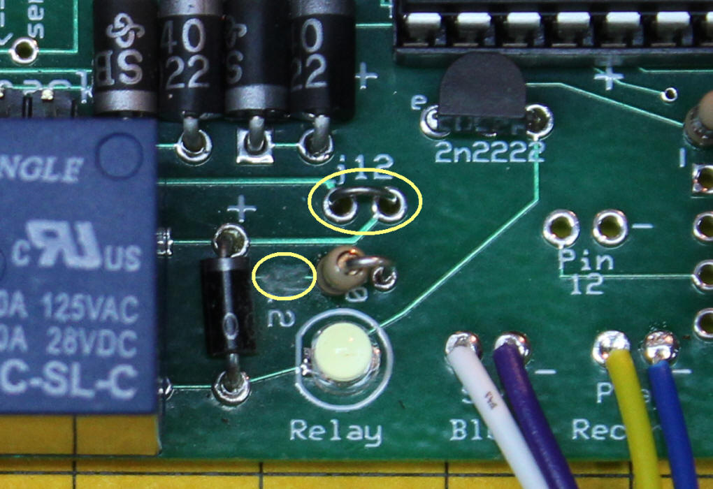
The last modification for 12 volts relay operation is to install either a solid jumper or a resistor in the two holes labeled "j12" and shown below circled in yellow. If you plan on operating your controller with 12 volts a small jumper will deliver that voltage to the relay. If you plan on running with a higher voltage power supply install an appropriate resistor. I have had good success with a pair of 470 ohm resistors in parallel (giving 235 ohms) with power supplies up to 19 volts. Above 19 volts a single 470 ohm resistor should work. Be sure to use a 1/4 or 1/2 watt resistor as they can get pretty warm. You may notice that there is another label "j12" that is not visible in this photo (it is under the relay) - it can be ignored.
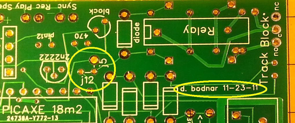
Relay notes for 11-23-11 board version
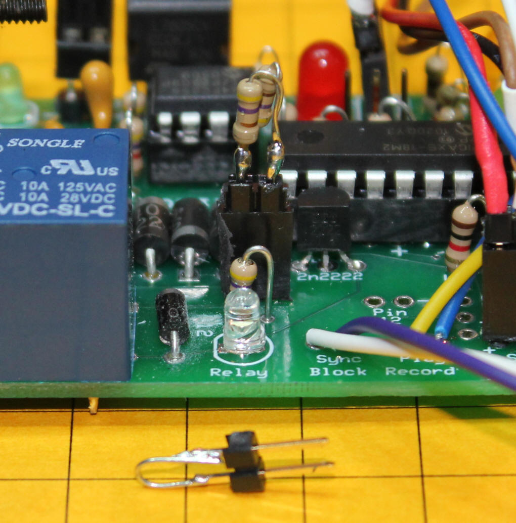
Here you can see how I have installed a 2 pin socket onto the jumper holes and plugged in a header with the two 470 ohm resistors in parallel. At the bottom of the photo is the jumper plug-in that I can substitute for the resistors when I operate from 12 volts.
The LED seen above shows the state of the relay. When the relay is open (off) the LED is off. When it is closed the LED is on. An LED of any color or size can be used. A memory IC that utilizes the I2C protocol is installed to record the data that is produced while recording. The I2C protocol allows the PICAXE to communicate with the memory chip using only two data pins. The parts list specifies a 24LS256. The controller records about 50 readings per second and the IC can record a bit more than 32,000 readings. This gives 32,000 / 50 = 640 seconds of recording or about 10 minutes. There is another I2C memory chip, the 24LS512, that can record twice as much information or about 64,000 readings giving over 20 minutes of recording time. There are also larger chips but they become difficult to program as their capacity exceeds the size of a word variable in the PICAXE.
Using the Recorder When the switch is set to PLAY the previously recorded train movements are played back and the train runs with the same behavior (speed, pauses and direction changes) as during the recording run. Dealing with Sync Errors
This inaccuracy can be mitigated to some extent by the use of a "sync block" that is used to consistently start and stop the train at a fixed point at the beginning and end of each playback. This block is controlled by a relay that is added to the PICAXE circuit. The relay is activated by pressing the sync button at some time before the train reaches the block at the end of each recording. As you approach the block after deactivating it the speed should be decreased so that the train enters the block slowly. Be sure to keep the speed control set to the same slow speed for a few seconds after the train enters the block to keep a train that may be out of sync moving till it gets to the block. Failing to do this can have the train stop before getting to the sync block throwing everything off. After the pause change to PLAY and the recorded run will be replayed. If the controller is used with a point-to-point layout that has diodes at each end a separate sync block is not needed. Every time the train passes the diode it will stop and will be back in sync when it restarts. See: http://www.trainelectronics.com/autoreverse/track_diodes/track_modification.htm for information on how these diodes can be installed. An optional "Start" button can be added to the circuit to have the train start up while in play mode only after this button is pressed. This button would be used at Children's Hospital and on similar viewer operated layouts. |
|
| Track Wiring In a loop layout the stop block should be two or three times the length of the locomotive. It is connected to the block power contacts as shown and the track power is connected to both rails of the track.
|
|
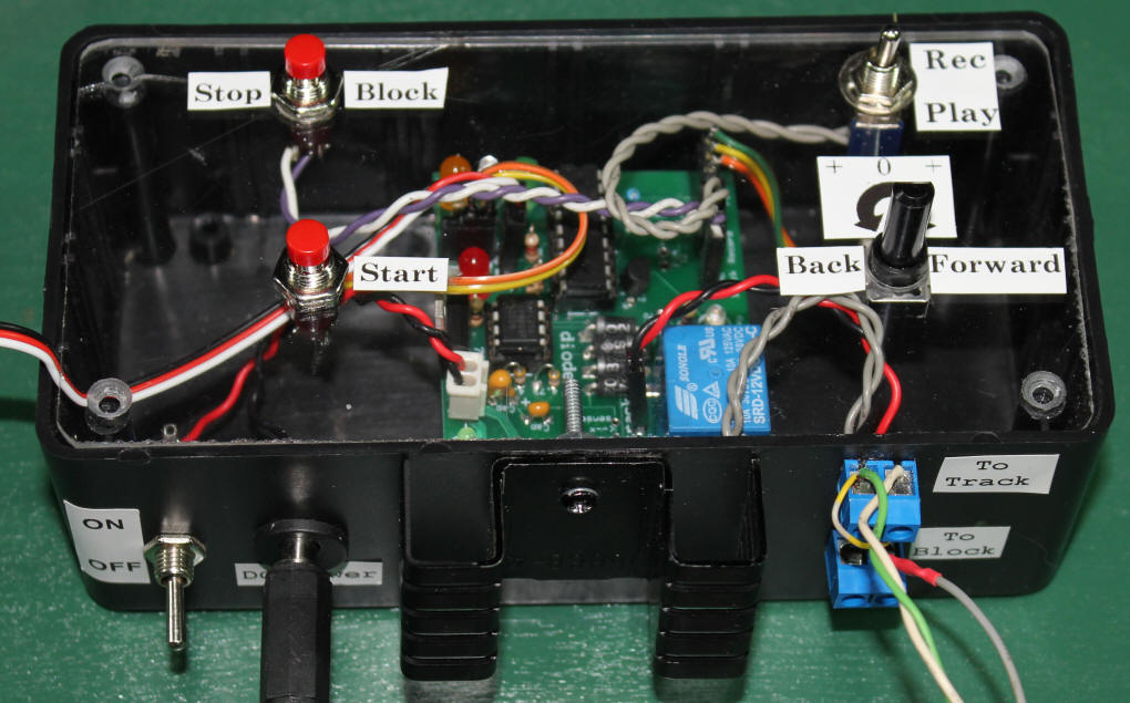
| Prototype Recorder The controls for the recorder have been mounted on a piece of Plexiglas. The Speed pot is in the lower right, the Record / Play switch is above it and the Stop Block and Start buttons are to the left. The heat sink extends through the project box. The track and block connections are to its right and the power plug and on / off switch are to its left.
|
|
| The schematic shows both the IR Receiver and
switch SW3 connected to pin 8 on the PICAXE. Only one of these can
be connected at a time.
|
|
|
Important Note on Recording: Be sure to run your train or trolley till it gets warm (2 minutes is plenty) before recording as a cold motor with cold lubrication runs quite a bit more slowly than when warm. This will give you a much better chance of having a repeatable run. |
|
|
Software - The Latest and Greatest Control Program |
|
| A Kit is Available A kit that is made up of all of the parts shown in the article is available from the author. All you need to supply is a power supply and a motor to control. The cost of the kit is $80 + shipping. I can also supply a wired and tested unit but my hope is that most users will enjoy the experience of building the kit themselves. |
|
| Going Farther The record / playback program takes up less than 1/2 of the program memory on the PICAXE so there is lots of room for experimentation. With some software modifications the unit could easily be converted so that it not only records train movements but also throws switches and triggers sounds based on train activity. The only limit is your programming skill and imagination! |
|
| Video This video shows the controller recording a trolley's run on a small layout then replaying it. The test track & trolley are N-scale but the controller will work with any DC powered train including HO and G-scale. As you can see this is an ideal system for demonstration railroads. We recently set it up at the Carnegie Science Center during a weekend of train related science demonstrations and let the young visitors record and playback a session. They really enjoyed it and, I am happy to report, it worked perfectly for two full days of operation. Right
click the box below and select PLAY or click here for a larger, higher resolution version in AVI format |
| Prototype Operation A prototype unit was constructed and is shown here. The controls are: SPEED - a potentiometer that sets the speed of the train when in PLAY mode. Turn the pot left to speed up in one direction. Put it in the center position to stop. Turn the pot to the right to speed up in the other direction PLAY / RECORD - a toggle switch that selects the operation mode START - a pushbutton switch that can be activated by the ENABLE / DISABLE switch. If set to ENABLE the train will play back a session only after pressing the START button. If set to DISABLE the recording will be played back over and over. BLOCK - a pushbutton switch that activates the block sync relay. If you are using a stop block press this button as the train approaches the stop block and it will come to a complete stop re-synchronizing its operation. Remember to keep the power on for a few seconds to allow the train to enter the stop block should it be slightly out of sync.
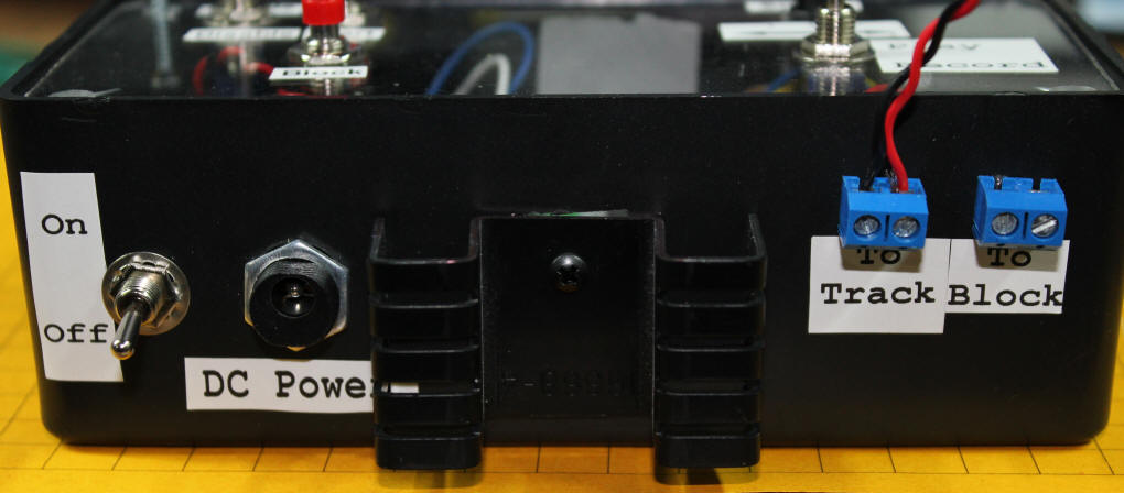
This view of the side of the prototype unit shows the ON / OFF switch, DC POWER connection and the two pairs of output connections. The first is labeled "To Track". These two contacts go to the track (big surprise, eh?). The other two connections, labeled "To Block" are for the stop block. Connect one terminal to the uncut section of track and the other to the cut section of track so that power can be supplied to the stop block when the relay is not active.
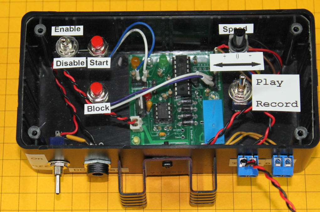
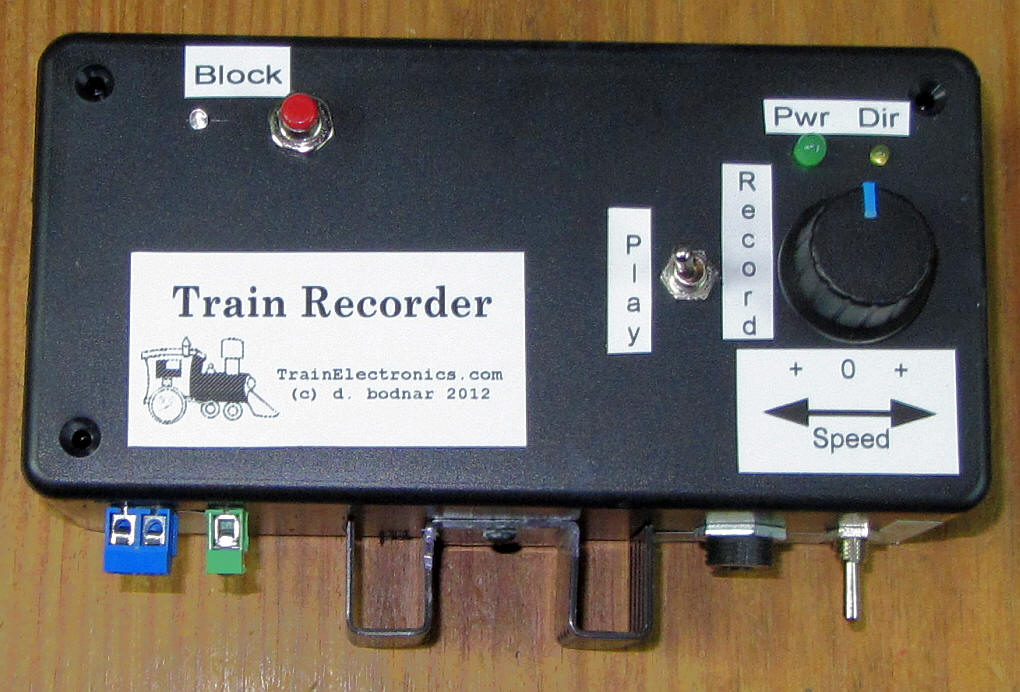
This is a second prototype that has simplified controls. The Speed is adjusted with the knob on the right. The larger green LED shows the power level and the smaller LED next to it indicates direction. The Play / Record switch is to the left of the speed control. The LED and switch in the upper left are for the block sync relay. When the relay is active and the block is unpowered the LED is lit.
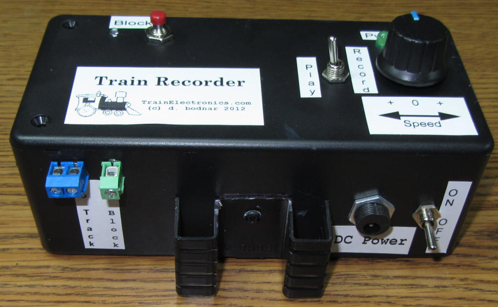
This side view shows the power connections and on/off switch on the right. The track is connected to the two blue terminals on the left. The cut section of the block is connected to the single green terminal. NOTE: The wire on the right side of the blue terminal must go to the same rail (inner or outer) that the block goes to. If it is not wired this way it will not work!
|