| Introduction For as long as I have been writing about model railroad electronics I have been asked about the "best" power controller (sometimes called a transformer or power pack) to buy. I am never comfortable recommending specific units as the price and quality can vary dramatically from brand-to-brand. The needs of different scales varies as well. I frequently recommend that hobbyists build their own power control unit using off-the-shelf parts. This way the controller can be tailored to specific needs and budgets. In this article I would like to explore such home made DC power controllers and how you can build one yourself. Note that this discussion is limited to DC power supplies and not AC, such as those used with Lionel and American Flyer trains. |
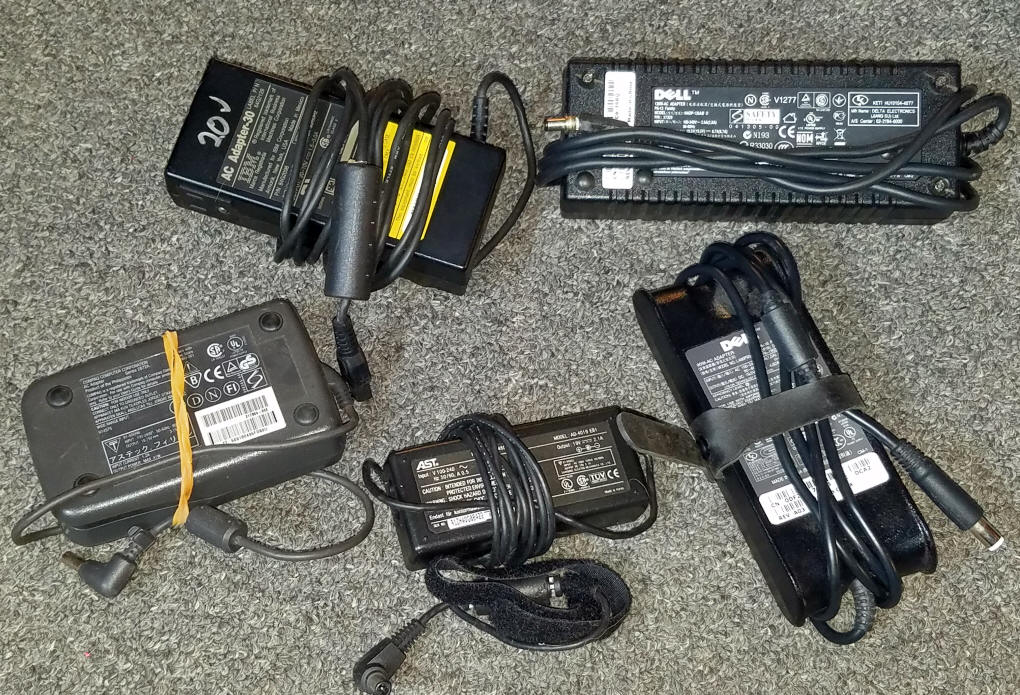
| Fixed Voltage Power Supply First we need a fixed voltage power supply that takes 110 volt house current and converts it to a fixed DC voltage. This fixed voltage varies from gauge to gauge. G-Scale trains typically run with up to 24 volts, HO-Scale is about 16 volts and N-Scale needs as little as 10 or 12 volts. My favorite source for fixed voltage power supplies is retired and repurposed laptop power supplies. They supply clean, consistent, regulated power. Their output voltage ranges from 12 volts (for older laptops) to 19 or so volts for more contemporary power supplies. Many of them can supply 3 or 4 amps of current, more than enough for many layouts. These power supplies are the easiest to modify for use. They also are in an insulated plastic case that helps with safe operation. If you don't have access to used laptop supplies you can find them on eBay, Amazon and other on-line sources. Here is a link that I have used http://www.mpja.com/Adapter-Power-Supplies/departments/475/ - Compact insulated power supplies - 12, 16, 19 and 24 volt units are available for $10 or less. And don't forget to ask your friends and family to save their laptop power supplies for you when they retire a computer.
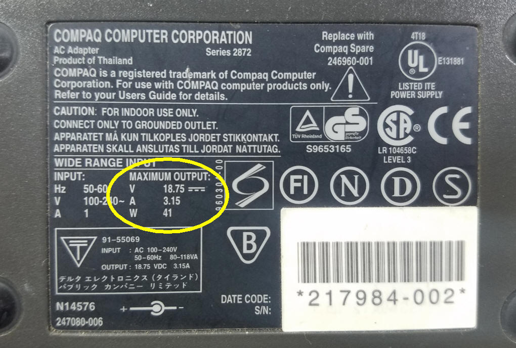
This photo shows the output voltage and current supplied by a Compaq laptop power supply. 18.75 is sufficient for most G-scale trains and 3+ amps should run many trains.
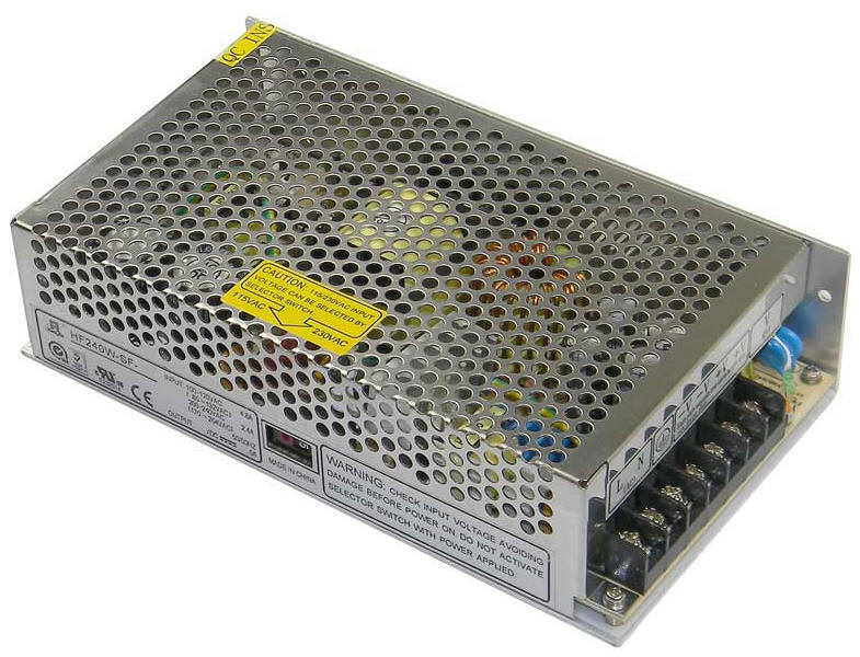
Another option, especially if you need to have more current available, is a fixed voltage supply that is designed for larger computers. A great many companies make computer grade fixed voltage power supplies. These frequently come in a metal case, often with exposed screws where you attach them to a 110 volt power cord. DO NOT use this style of power supply unless you properly insulate the high voltage side of the unit. The supply shown here is from Marlin P Jones. It is rated at 24 volts at 10 amps and costs only $35.00. This style power supply is also available in a version for 12 volts. This vendor also sells a 15 volt, 4 amp unit for about $20.00
|
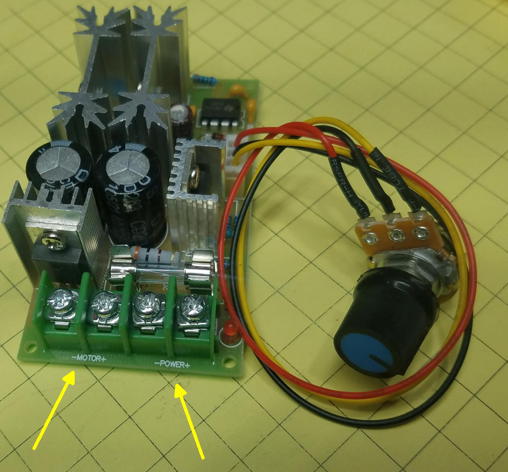
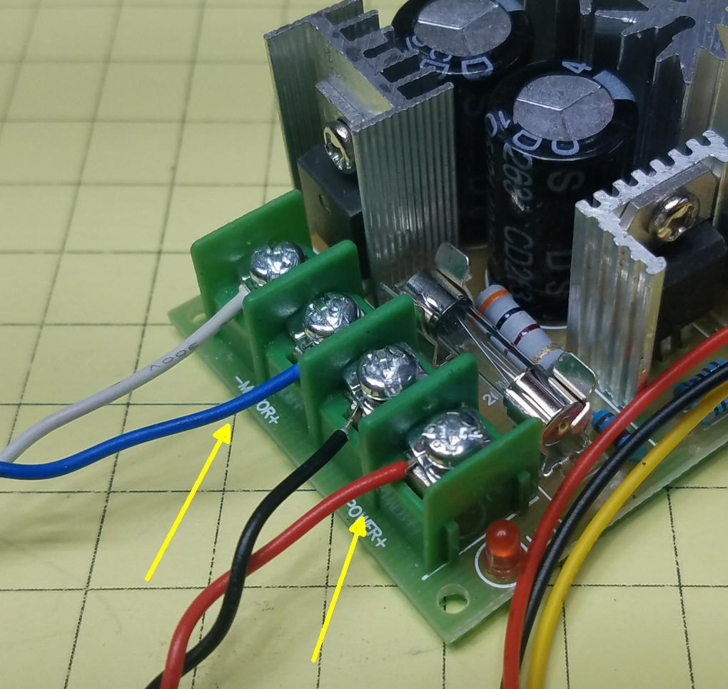
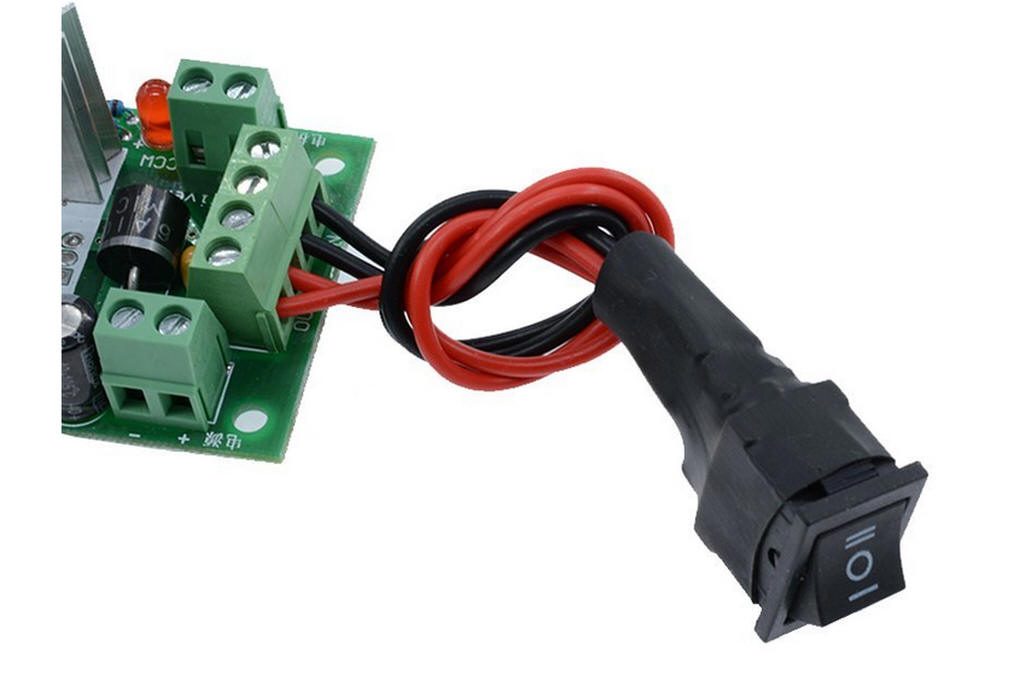
| Motor Speed Control Unless you want your trains to run at full speed all of the time some sort of variable power motor controller needs to go between the fixed voltage power supply and the track. These speed controllers take a fixed DC voltage and, using PWM, provide a variable output that ranges from 0 volts to just a bit less than the input voltage. I found this power controller on Amazon and eBay for less than $12. It has a control knob that is used to vary the speed and this control device is on leads so that it can easily be mounted inside of a box or other enclosure.
There are four screws on the board.  Two are for the motor and two for the fixed voltage supply.
Be very careful that you attach the positive terminal from the power supply to the + Power terminal on the board
and the negative terminal to the - Power terminal.
The blue/white wires go to the  motor or track and the red/black wires go to the output of the power supply.
|
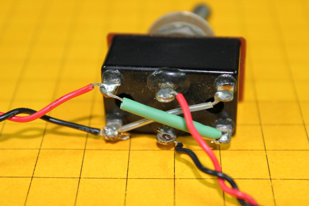
| Reversing Switch Most of us like to have the option of reversing a train as well as adjusting its speed. Unless you buy a motor speed controller that includes a reversing switch you need to add a reversing switch to your unit. All you need is a Double Pole Double Throw switch (abbreviated as DPDT). Any DPDT toggle switch should work so long as it is rated for at least the number of amps that your speed control can supply. These switches are available from Amazon, eBay and most electrical supply sources. You will note that some come with a center "off" position. They are typically described as ON/OFF/ON. While this is not necessary it can come in handy should you want to completely remove power from your layout. Be careful that you do not purchase a DPDT switch that has MOMENTARY in its description as the switch lever will spring back to OFF when released. DPDT switches have six terminals. Two in the center and two at each end. The wiring to make it a reversing switch is shown here. Power comes in through the red/black wires that go to the center pair of terminals. The outside four terminals are wired in an "X" configuration. Power goes out to the motor or track through the red/black wires that go to the left.
This graphic show the path of the circuit when the switch has its lever up and down. You can see that the bottom terminals are connected when the lever is up and the top terminals connect with the lever down.
This simple schematic shows the wiring of the controller and switch.
|
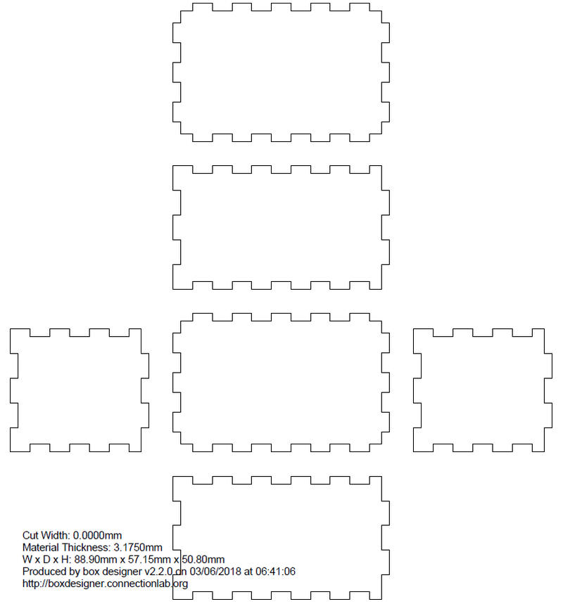
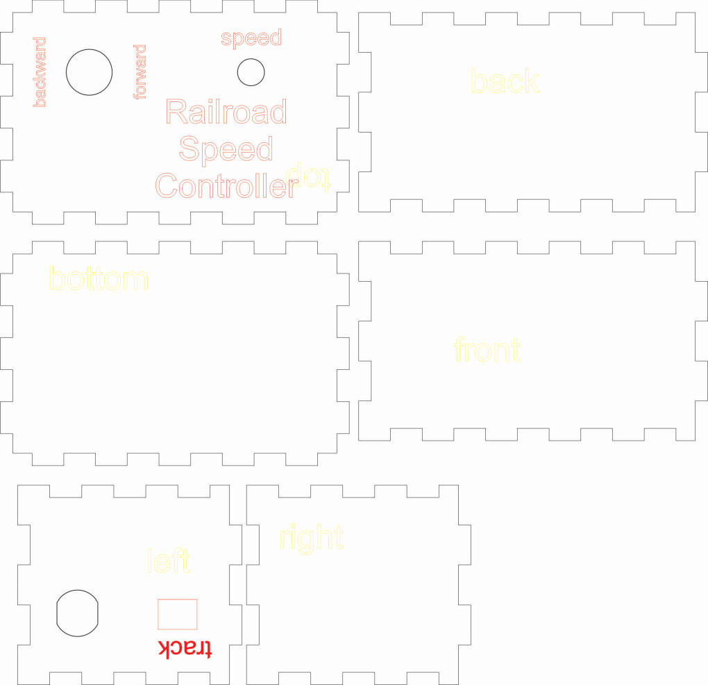
| Putting It All Together I used a program on the web to design a box for the controller, switch and speed knob. The output from http://boxdesigner.connectionlab.org/ is shown here. It is 3.5" x 2.25" x 2".
The PDF from the box maker is imported into CorelDraw where holes and labels are added.
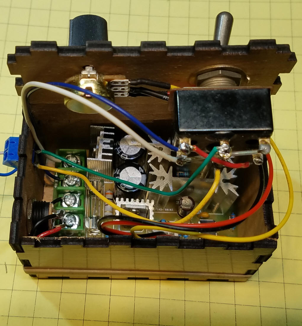
The controller, wired to the switch and input and output connectors, is shown here before it was glued together.
The components fit snugly. If you plan on running the controller close to its maximum amperage a larger box with ventilation (perhaps with a powered fan) would be a wise choice. For smaller, single train layouts very little heat will be generated and the small box should be fine.
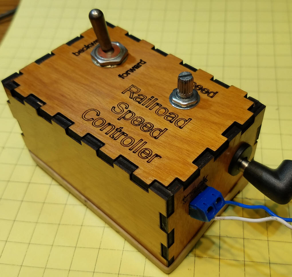
Here it is ready to go.
|
| Motor Speed Control with Reverse Switch You can also find speed controllers that include a DPDT reversing switch. Here is one example that I purchased from Amazon.
The only disadvantage with the included switch is its rectangular shape, as such components can be more difficult to neatly install in a control box than those that fit into a round hole. You can, if you prefer a standard DPDT switch, wire it as shown earlier and connect the two input wires to the red wire terminals and the output wires to the black wire terminals.
|
| Fuses and Circuit Breakers For safe operation some sort of fuse or circuit breaker is a must. If you don't expect too many derailments or short circuits a fuse is an inexpensive option. Fuse holders can be purchased for a few dollars from Amazon, eBay and other sources. Select a fuse that is no larger in amperage than the power you are sending to the track. I like to keep fuse size to the lowest value that I can use with the trains I am running. For example, if you measure your train pulling 1.5 amps select a 2 amp fuse even if your power supply and controller are rated for 10 or more amps. I also like to purchase FAST BLOW fuses as they cut the circuit more rapidly than standard fuses. If you find that you are replacing fuses all the time you might want to move to a circuit breaker. They do the same job as a fuse but are resettable, usually by pressing a button. I put my fuses in on the output side of the speed controller. That should have them blow quickly should a short circuit occur. |
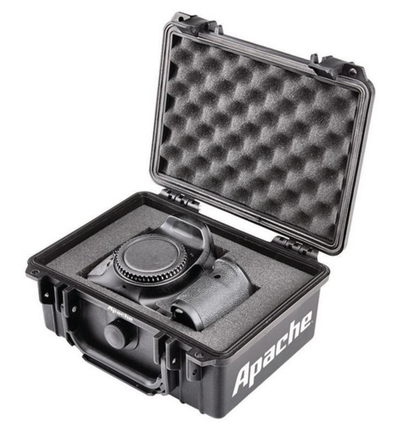
| Other Enclosures The laser cut box that I designed and fabricated works well but there are other mounting options. I have installed similar controllers into small toolboxes and Tupperware. I visited my local Harbor Freight the other day and found these two boxes that work very well as housings for the controller. This ammo box is plastic and measures about 9" x 4" x 6" high. That is more than enough space for most power supplies and motor controllers. As I write this they are on sale for about $6.00.
This case is also a good candidate. The inside dimensions are about 8.25" x 6" x 3" and they are frequently on sale for about $10.
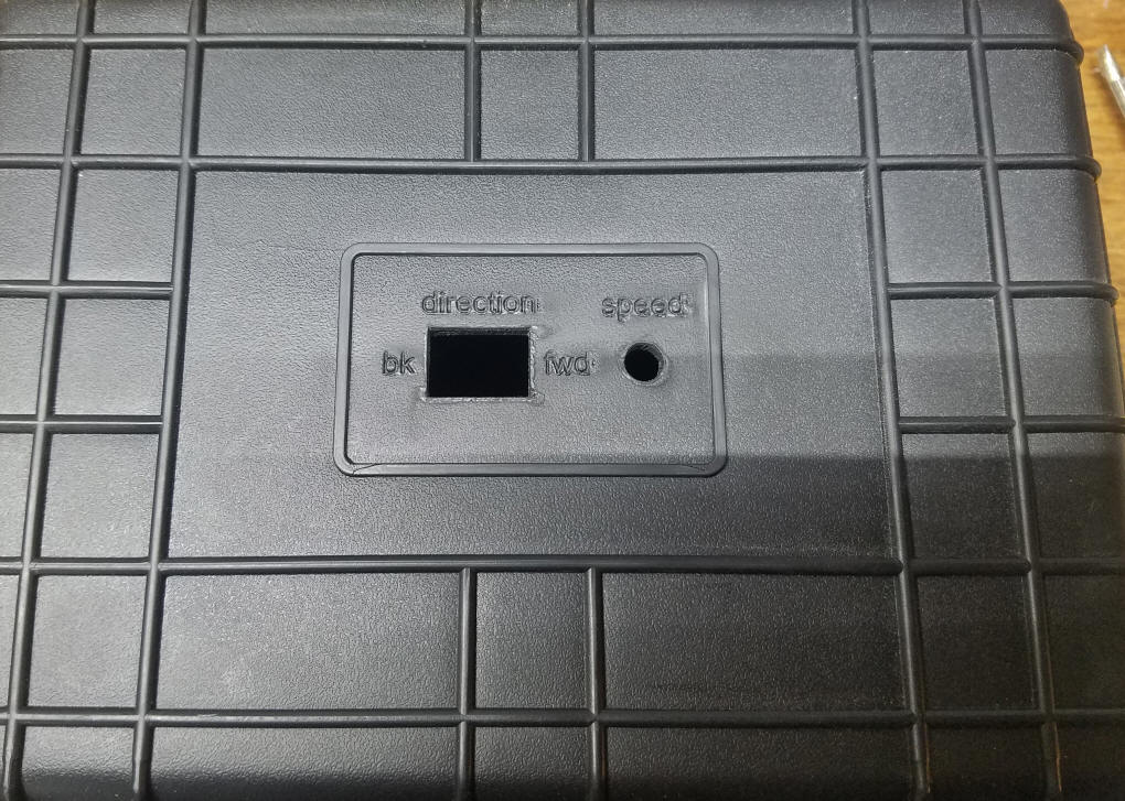
I removed the label on the top of the box and used my laser cutter to cut two holes and add labels. If you don't have access to a laser cutter the hole can be made with a drill and the square opening for the directional switch could be drilled and filed to this shape. You could also replace the square switch for reversing with a DPDT switch that fits into a round hole.
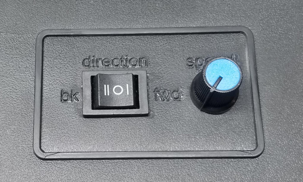
This close-up shows the speed and direction controls after they have been installed in the top of the case. Note that the direction switch has a center "OFF" position.
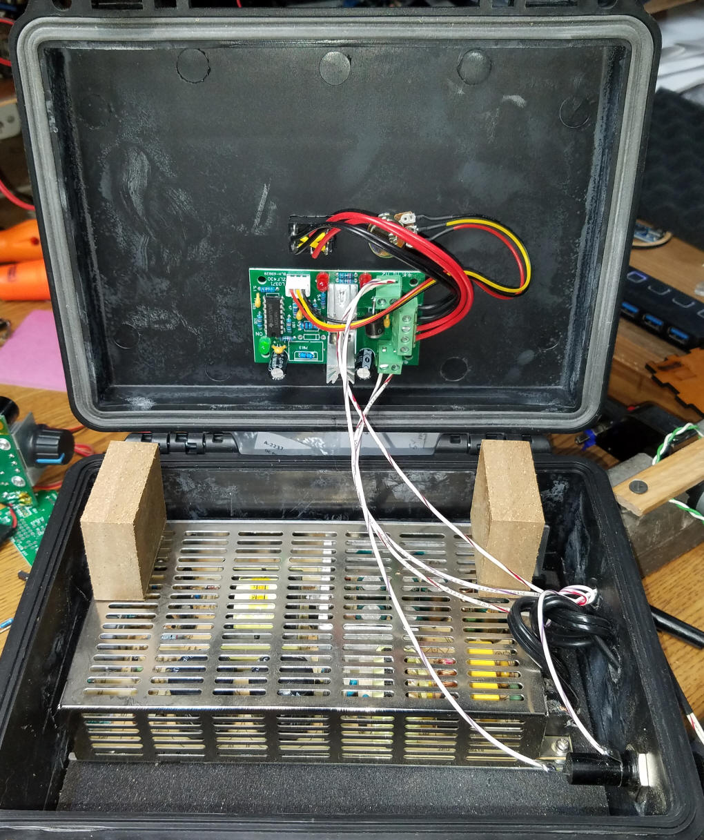
The speed controller (the one with the direction switch that I got from Amazon) is attached to the inside of the top with self adhesive Velcro. The two blocks that are affixed to the metal power supply push down on it when the lid is closed, holding it in place.
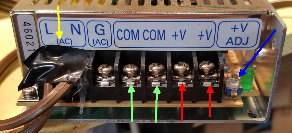
The connections to the 24 volt power supply are shown here. The yellow arrow points to where the 110 volts AC go into the supply. I covered the screws with silicon glue and put tape on top to insulate the connections. Not a perfect solution but, along with keeping the contacts in plastic case, it should keep fingers from coming in contact with them. There are two screws for negative DC output, green arrows, and two for positive DC, red arrows. You can adjust the output voltage a bit by turning the small potentiometer at the far right, blue arrow. The one I am using can be varied from 20 to 26 volts.
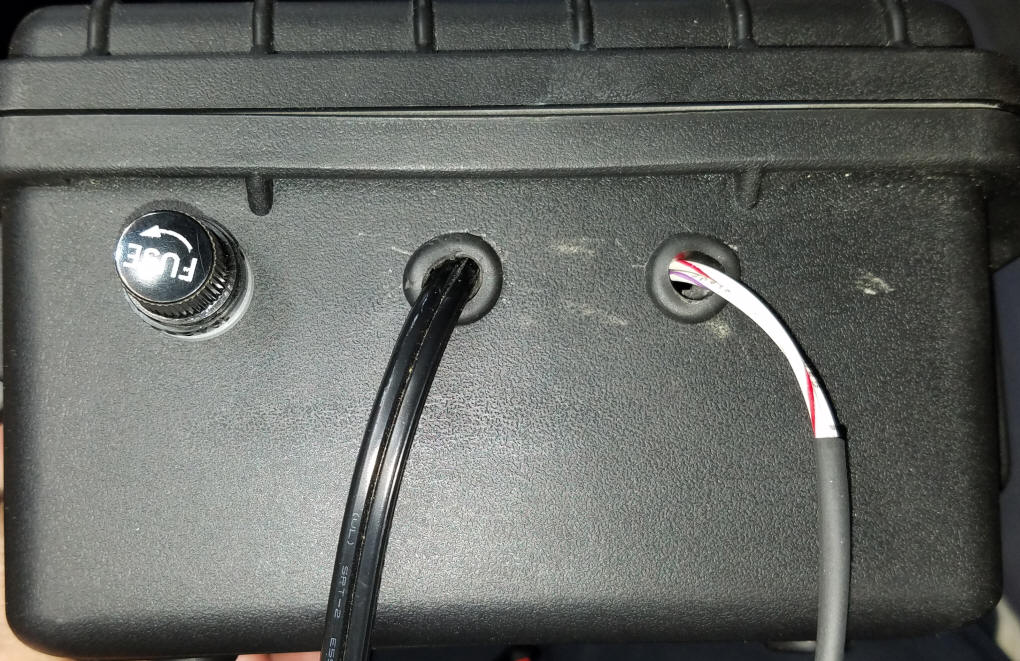
This is a photo of the side of the case. Power goes in through the center cord and DC comes out through the cord on the right. The fuse holder is to the left.
|
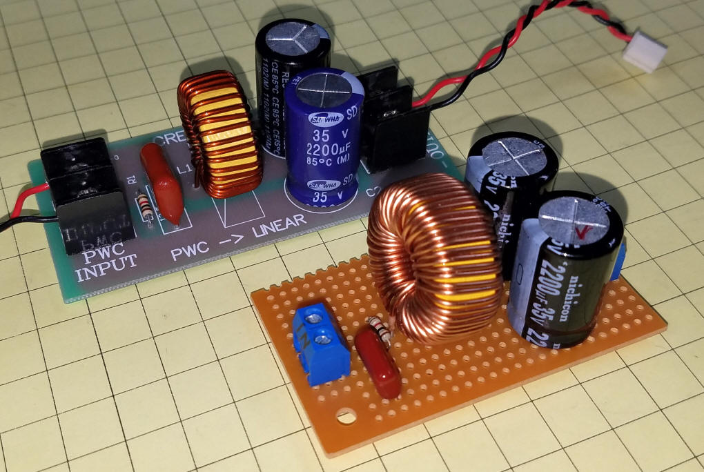
| PWM to Linear Output Some model railroad electronics don't play well with PWM (also called PWC) speed controllers. This is especially true with some sound cards. I wrote an article about this as it relates to the Revolution system but it holds true for most if not all, PWM controllers - the article is here http://www.trainelectronics.com/ART5700TrainEngineerRevolution/PWC--Linear_CRE57091/index.htm The schematic for the converter is quite simple and can be made on a prototype board.
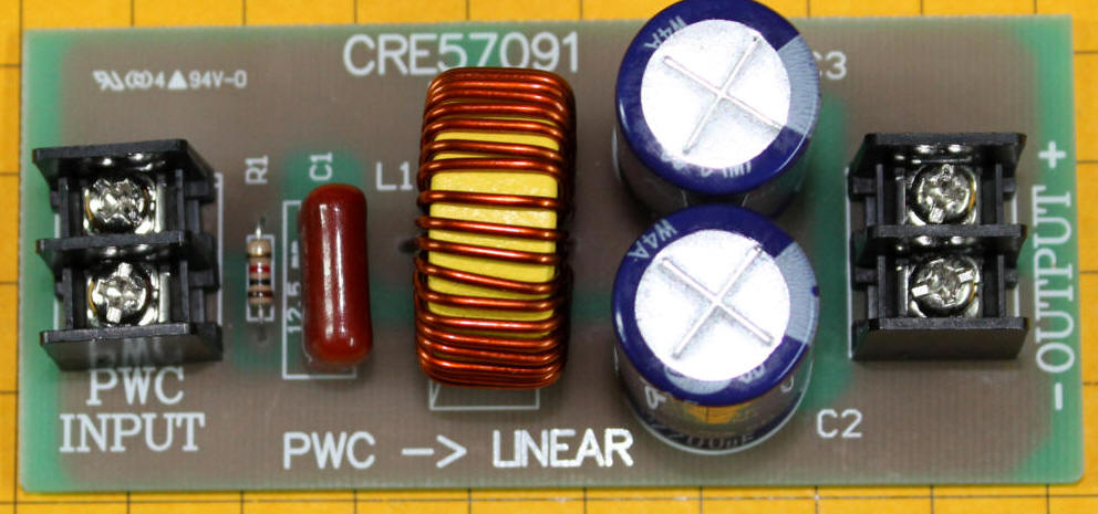
The device shown here was sold by Aristo Craft and follows the schematic above. It may still be available from some vendors such as http://rldhobbies.com/rev-57091.aspx
Here the Aristo Craft version is shown behind one I built from parts.
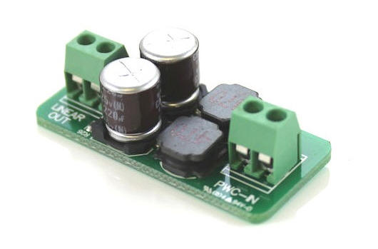
There is a 0.5 amp version of this circuit that can be purchased here: http://www.revoelectronics.com/product/lamp-pwc-linear-board.html
|