[home]

Raspberry Pi - single board Linux computer
revised 10-20-13  d. bodnar
Serial From Pi to PIC or PICAXE
NOTE: Serial from PIC to Pi Problem Resolved


I have been working with the Raspberry Pi for a few months and have had a great time experimenting.

I plan on documenting some of the things that I have been able to do and observations that I have made.

My latest project is to use the Pi to read temperature from multiple DS18B20 sensors and graph the results - my notes are here

I have also been working on a Temperature / Humidity grapher - notes re here:

http://www.trainelectronics.com/RaspberryPi/Graph_Humidity/


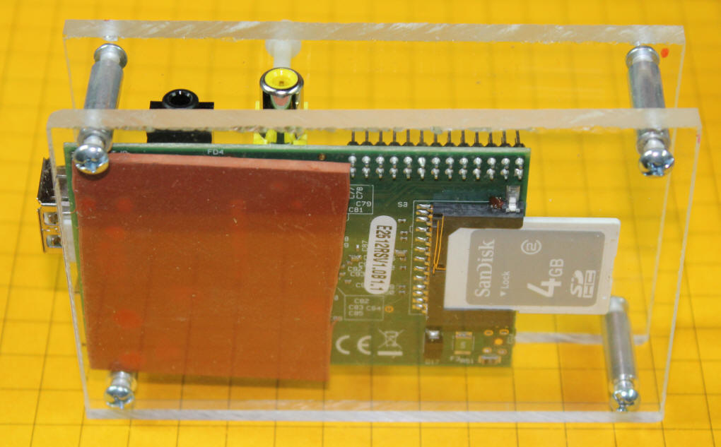
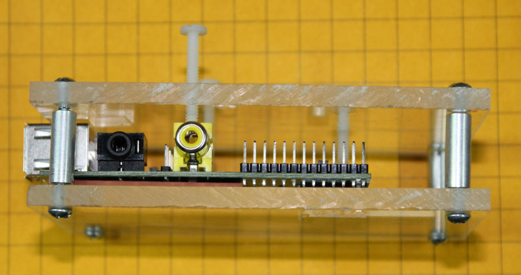
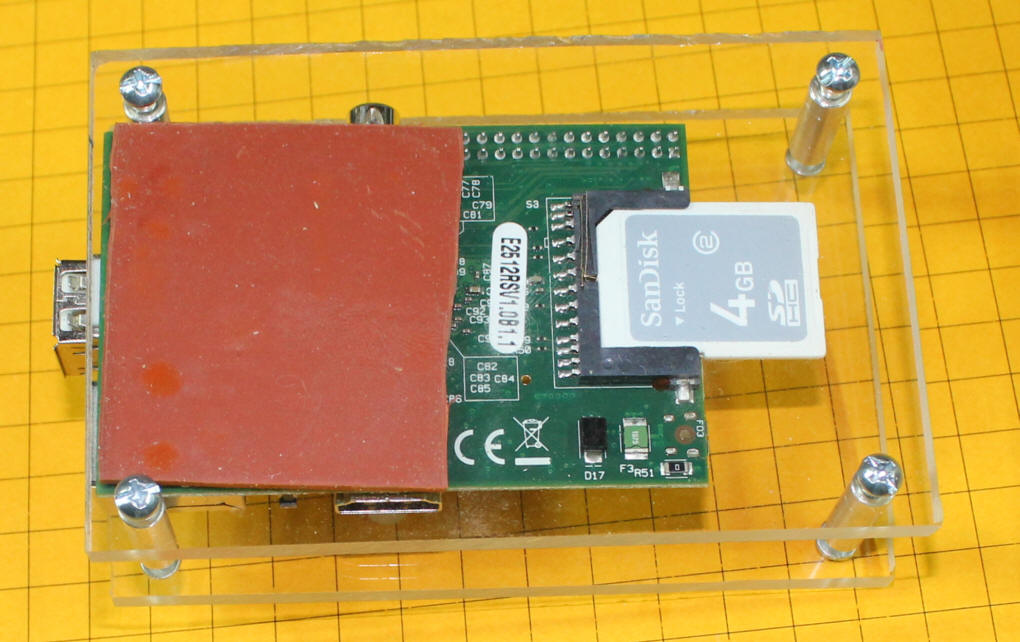
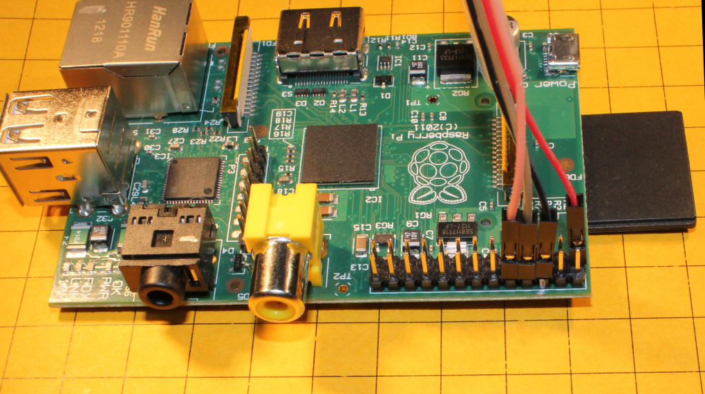
Easy Case
I made a protective Plexiglas case using materials that I found at my local (well stocked) hardware store.

Two pieces of 1/4" Plexiglas are held apart by 3/4" spacers (stand offs).  The Plexiglas is 4.5" x 3".

There are three nylon screws that go through tapped holes in the top piece of Plexiglas to put gentle pressure on three points on the board, holding it firmly in place.  The screws are 6 x 32 and 1" long.  The screws that goes onto the yellow video out connector is way too long and will be cut down in length.

If you can't find nylon screws locally I purchased 8-32 x 1" screws from MicroFasteners.com

A small piece of 1/8" thick gasket material (2" x 1.75") goes under the side of the board away from the SD car socket.  This padding helps to level out the bottom and it keeps the board from moving.  The gasket material was found in the plumbing department.  Make sure you test it to make sure that it DOES NOT conduct electricity before using it!  The material I found is rubber and works well.  It is similar to this item from Sears.

A slot can be cut into the top piece of Plexiglas it access to the I/O pins is needed.
If you look carefully at the spacers in this photo you will note that the screws are not fully tightened but there is a small space between the stand off and the Plexiglas.  A small washer will be added to fill this space.


UNDER CONSTRUCTION!!!

Using the Pi to Communicate with a Pic (or PICAXE) Microcontroller
The serial port on the Raspberry Pi can be used to send data strings (text and/or data) to other devices.  The objective of this project is to get the Pi to send meaningful data to a Pic or PICAXE processor.

Testing the Serial Output
Start a terminal program on the PC.  Set it to 115200 baud, N, 8, 1 - no flow control.   Make sure that the correct com port is selected.

Connect the UART pins from the Pi to you computer's serial port using the MAX3232 described below.

To send a serial string from the Pi's command line type the following:

echo "hello" > /dev/ttyAMA0             and press ENTER    - note that the last character is a zero not an "O"

To send with a carriage return and line feed:

echo -e "hello \r\n" > /dev/ttyAMA0         and press ENTER

Modification to Shell file to Send Serial
I modified the shell script that was shared here: 
http://www.instructables.com/id/Web-Control-of-Raspberry-Pi-GPIO/?ALLSTEPS so that it would output serial data via the UART that I could receive with a PIC or PICAXE so that the web input would control the microcontroller to do stuff!

The modified GPIOServer.sh file is here:  RaspberryPi/GPIOServer-EchoWorking.sh.txt

Here are the changes I made:

  1. In each of the 8 IF THEN ELSE statements I added code to set 8 different single letter variables (a-->h) to either 1 (if true) of 0 (if false)
    Note the line that says a=1 just above the ELSE statement and the line that says a=0 just above FI - this is repeated with b=1 and b=0, c=1 and c=0 and so on
  2. At the end of the 8 IF THEN ELSE statements I added an ECHO statement to send a set of 0's and 1's representing the state of the 8 switches - the lines that I added are here:

    echo "xyz"$a$b$c$d$e$f$g$h
    echo -e "xyz$a$b$c$d$e$f$g$h \r\n" > /dev/ttyAMA0

    The first line echo's the string of 1'a and 0's to the screen while the 2nd line sends the same thing to the serial port
    The -e    and        \r\n    adds a carriage return and line feed
  1. The results that are sent to the screen and serial port look like this:
    xyz0011010101      or xyz10001000   depending on the setting of the bits on the web page
    the "xyz" at the start allows the PIC or PICAXE to start importing data after that string is seen.
     
  2. I also changed the baud rate from 115200 to 2400 as the PIC and PICAXE can't handle  the higher speed.  Notes on changing the baud rate are here: http://www.andremiller.net/content/raspberry-pi-and-arduino-via-gpio-uart

PICAXE 14M2 Program
This is the test program that successfully picks up data from the Pi and sends it back out to a terminal program


SYMBOL SerialIn =c.0 'pin 7

SYMBOL Delay = b6

SYMBOL cameras = b5

setfreq m16   'run the PICAXE at its highest speed (16MHz)

Startit:

serin c.0,n2400_16,("xyz"),bit0,bit1,bit2,bit3,bit4,bit5,bit6,bit7 ' get 8 characters only after seeing "xyz"

cameras=b0 & %00001111    'cameras to use are the last 4 bits
delay = b0 & %11110000    'delay time is the first 4 bits

b1=b1+1   'just a counter to show it is working
delay=delay/16  ' move the delay bits four places to the right

serout 1,N2400_16,(#b1," Cameras = ",#cameras," Delay= ",#Delay,13,10)   'send to terminal on PC for testing

goto Startit:


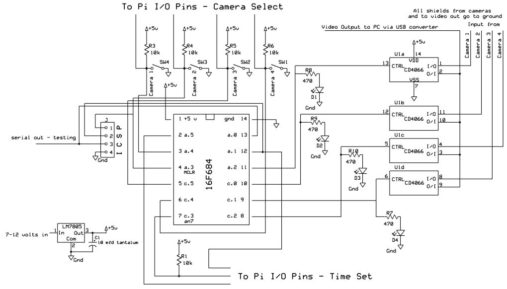
PICAXE 14M2 Program for Camera Controller


'01-13-2012 v 1.9 revised for latest board version
' d. bodnar
'Video Switcher
'w0 = b1 : b0
'w1 = b3 : b2
'w2 = b5 : b4
'w3 = b7 : b6
'w4 = b9 : b8
'w5 = b11 : b10
'w6 = b13 : b12 etc
#PICAXE 14M2
'#TERMINAL 19200
setfreq m16 'run the PICAXE at its highest speed (16MHz)


SYMBOL SerialIn =c.0 'pin 7

SYMBOL Camera1 = 2
SYMBOL Camera2 = 3
SYMBOL Camera3 = 5
SYMBOL Camera4 = 4
SYMBOL Delay = w6
SYMBOL UseCamera4 = bit3
SYMBOL UseCamera3 = bit2
SYMBOL UseCamera2 = bit1
SYMBOL UseCamera1 = bit0


SYMBOL cameras = b5


pause 1000
serout 1,N2400_16,("Video Switcher",13,10)
serout 1,N2400_16,("(c) d. bodnar v 2.0 Pi Serial 07-29-12",13,10)


Start:

serin c.0,n2400_16,("xyz"),bit0,bit1,bit2,bit3,bit4,bit5,bit6,bit7 ' get 8 characters only after seeing "xyz"

cameras=b0 & %00001111 'cameras to use are the last 4 bits
delay = b0 & %11110000 'delay time is the first 4 bits

b1=b1+1 'just a counter to show it is working
delay=delay/16 ' move the delay bits four places to the right
delay = 16-delay
serout 1,N2400_16,(#b1," Cameras = ",#cameras," Delay= ",#Delay,13,10) 'send to terminal on PC for testing


'READADC10 0, Delay

delay = delay * 1000*4
serout 1,N2400_16,("Delay Time = ",#delay,13,10)
'debug delay
IF UseCamera1=0 THEN
serout 1,N2400_16,("one",13,10)
LOW Camera2:LOW Camera3:LOW Camera4
HIGH Camera1
PAUSE Delay
ENDIF

IF UseCamera2=0 THEN
serout 1,N2400_16,("two",13,10)
LOW Camera1:LOW Camera3:LOW Camera4
HIGH Camera2
if usecamera3=1 and usecamera4=1 then
delay = delay -3000
PAUSE Delay 'skip delay if last
else
pause delay
endif
ENDIF

IF UseCamera3=0 THEN
serout 1,N2400_16,("three",13,10)
LOW Camera1:LOW Camera2:LOW Camera4
HIGH Camera3
if usecamera4=1 then
delay = delay - 3000
PAUSE Delay
else
pause delay
endif
ENDIF

IF UseCamera4=0 THEN
serout 1,N2400_16,("four",13,10)
LOW Camera1:LOW Camera2:LOW Camera3
HIGH Camera4
delay = delay - 3000
PAUSE Delay
ENDIF

IF UseCamera1=1 AND UseCamera2=1 AND UseCamera3=1 AND UseCamera4=1 THEN
serout 1,N2400_16,("NONE",13,10)
LOW Camera1:LOW Camera2:LOW Camera3:LOW Camera4
ENDIF

GOTO Start:


UNDER CONSTRUCTION!!!

Using the Pi to Control a Web Cam System
I have been using a four camera web cam system for some years. 
You can view the live video here.  The board that switches between cameras was originally designed to be operated by using four switches to select one or all of the cameras and a potentiometer to select the time that each camera would be active.  The project was featured in Make Magazine, Issue 30 in the Spring of 2012.  This article can be viewed here:  http://www.trainelectronics.com/WebCam/Article.htm

The objective of this project is to use the Raspberry Pi, and its web interface, to select cameras and time delay.  The project uses a number of routines and programs that have been written about using the Pi.  My hat is off to all of those contributors who made this work possible!

  1. Set up the Pi as shown here:  http://www.raspberrypi.org/quick-start-guide
     
  2. Set up the Pi for web control as shown here: http://www.instructables.com/id/Web-Control-of-Raspberry-Pi-GPIO/?ALLSTEPS - this gives you the ability to use a web server on any computer to remotely control the 8 IO pins on the Pi's expansion header.
     
  3. Build a plug & test board to connect to the header

    The board that I used  is from Sure Electronics - Each of the boards can be broken into four smaller boards like what I am using here.


    The in-line header is also from Sure.  It can easily be cut into two thirteen pin strips for our board.


    LEDs and 1K resistors were added to each I/O pin.  Note that the far left and far right sets of holes are connected to ground.


    Here is another view of the board.


  4. Test the board
    Turning pins on and off with the web interface should turn indicator LEDs on and off, too
     
  5. Modify the Web Cam Control board as shown in the schematic - the four switches are removed and they are connected to Pi I/O pins and three or the other pins are connected to Pi I/O pins to select scan time.
     
  6. Connect the IO pins to the Web Camera Control Board
    To interface the Pi, which is a 3.3 volt device, to the Web Camera Controller, which is a 5 volt circuit, can be done if all of the I/O pins on the Web Camera Controller are held high by 10k resistors.  If that is done the Pi's pins can be used to pull those pins low without any harmful voltages passing between the boards.  I have tested this for weeks and it works very well.
     
  7. Test!
     
  8. Revise the software on the Web Cam Controller (it uses a PIC 16F684) as shown in this listing
     
  9. Revise the web page to represent the camera controls


Connecting to the built-in RS-232 Port with a MAX3232
The Raspberry Pi has a built in RS-232 port that is available at pins 8 and 10 on the 26 pin expansion header.  In order to connect this port to a standard serial port on a PC or other device the 3.3 volt pulses that the Pi generates must be changed to normal RS-232 levels.

There are a number of articles on the Internet that show how to use the MAX3232 to make this change.  This is not a difficult device to use 
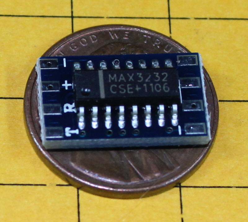
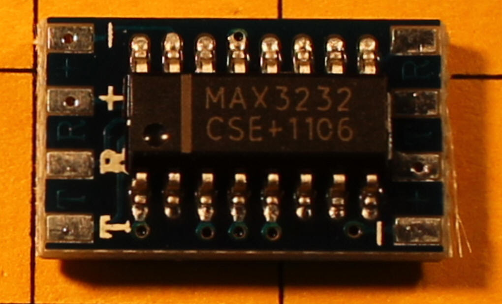
but requires five capacitors to be fully functional.  I found a complete MAX3232 board that includes a surface mount chip and the five 
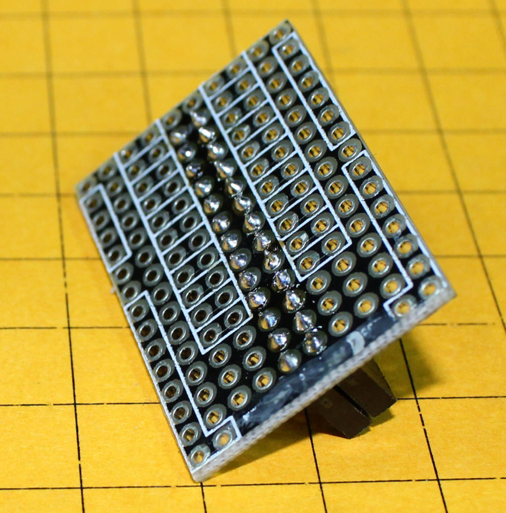
capacitors on a board that is only 15mm long and 9mm wide.

(that's Abe Lincoln under the board in this photo!)

These boards are available from SuntekStore  - here is a link to the board: 
http://www.suntekstore.com/goods-14002601-mini_rs232_to_ttl_converter_module_board_.html.  The cost is $2.09 with free shipping.  Note that they also sell these in sets of 5 for $6.57 and in sets of 10 for $12.05.  Quite a deal!

The board is not well documented.  Hopefully the notes below will get it working for you.

Here the top of the board and the MAX3232 chip can be seen.  Even though there are solder pads on this side of the board no connections are made here.

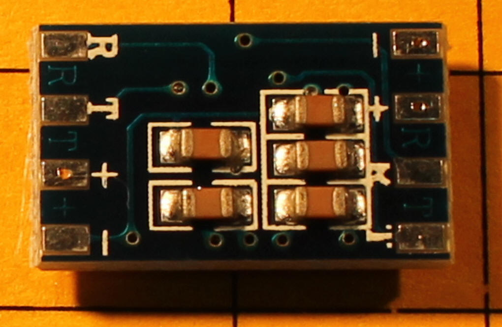
The back of the board is shown here.  The five small devices are surface mount capacitors.  I used the four solder pads on the left to connect to the Raspberry Pi's expansion header.  Three of the four pads (the one marked "+" is not used) go to the DB-9 that plugs into a PC's serial port.   The silk screen labeling on these pads is not very good.  The pads are labeled, from top to bottom, -, +, R, T.

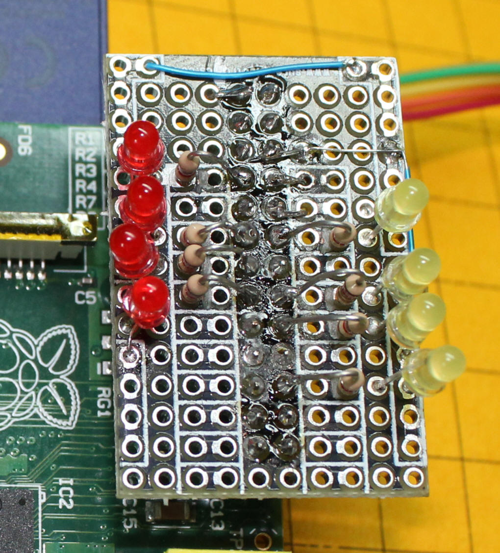
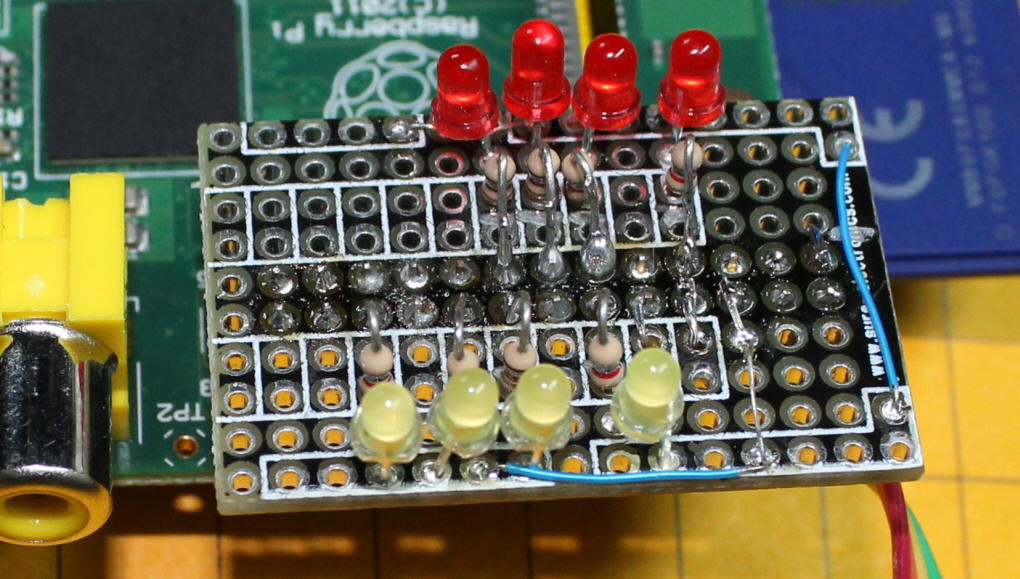
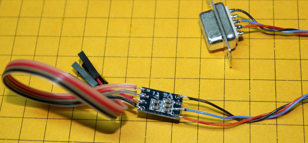
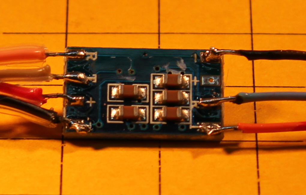
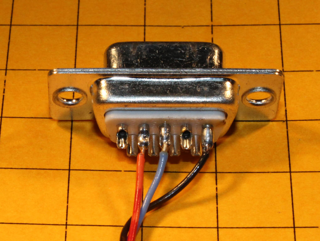
Here is a photo of the completed unit.  The DB-9 on the right goes to the PC's serial port.  Only 3 wires connect from it to the MAX3232 board, pin 5 (ground), pin 3 (transmit) and pin 2 (receive).  The four wires on the left of the board go to the pins on the Pi's expansion header.

The cable coming out from the left side goes to the Pi - these wires came from Deal Extreme and can be found with this link:  http://dx.com/p/30cm-breadboard-wires-for-electronic-diy-40-cable-pack-80207 .  I cut the 30cm wires in half and soldered the cut ends to the circuit board while the end with the female connectors go to the header on the Pi.  The colors used are black, red, brown and orange.

It is important to note that all wiring is done on the back of the board, that is the side of the board that has the 5 capacitors, not the side with the MAX3232 chip.

Once the wires and connected plug the four wires on the left of the board to the following pins on the Pi's expansion header:

  • Pin 1 - 3.3 volts - to + on MAX3232 board (red wire)
  • Pin 6 - ground - to - on MAX3232 board (black wire)
  • Pin 8 - UART TXD - to R on MAX3232 (orange wire)
  • Pin 10 - UART RDX - to T on MAX3232 (brown wire)

The other three connections go to the DB-9 serial plug.

  • DB-9 pin 5 to ground on MAX3232 (black wire)
  • DB-9 pin 3 to R on MAX3232 (blue wire)
  • DB-9 pin 2 to T on MAX3232 (orange wire)
     

To test the unit connect the DB-9 to a PC's serial port.  Connect the four connectors to the pins listed above on the Pi

Fire up the Pi and, once it boots, start a terminal program on the PC - set the terminal program to 115200 baud, no parity, 8 data bits and no flow control.  Press ENTER a few times and you should be rewarded by a login prompt.


Major Issue with Serial Receive from PICAXE or PIC processor!

I spent a few days getting errors on the PI (error number 11 mostly - time out or resource not ready) until I stumbled on this link:

http://www.hobbytronics.co.uk/raspberry-pi-serial-port

that tells you to disable the serial login function - that appears to have been what was killing the serial input from the weather station that I am working to interface with the Pi.  The serial would work for a dozen or so inputs from the PIC then would give an error.

Simply edit this file:  /etc/inittab

and put a remark symbol (#) before the line that includes "ttyAMA0" as below

#Spawn a getty on Raspberry Pi serial line
#T0:23:respawn:/sbin/getty -L ttyAMA0 115200 vt100

Bingo---- it worked reliably!

thanks to Hobby Electronics!


Python Code (name on my system "serial12-loop-OK5")


import time
import serial
s = serial.Serial("/dev/ttyAMA0", 9600, timeout=0.8)

for i in range (1,11111):
print "at top", i
    data = s.readline() #reads up to 1024 characters, or until \r\n
    if (data.startswith('D')):
        print "found D"
        print data
        time.sleep(1)
 

PIC 12F683 Code:

'WX Date to Pi test d. bodnar 8-3-13

option_reg.7=0 'turn on weak pull ups
wpu = %00100010 'weak pull ups on pin GPIO.5 (Pin 2) only

Include "modedefs.bas"
ansel = 0
cmcon0 = 7
Serial_out var gpio.0 'pin 7 '
TIP101 var gpio.2 'pin 5 hpwm 1
NotUsed2 var gpio.5 'pin 2

'OSCCON = %01110000 ' Set to 8MHz
Serout serial_out,n9600,[13,10,"d. bodnar Ver 1.0 Send serial to Raspberry Pi",13,10]
Serout serial_out,n9600,[13,10,"Careful with oscillator and baud rate!",13,10]
Serout serial_out,n9600,[13,10,"08-03-13",13,10]
Serout serial_out,n9600,[13,10,"MUST disable serial login on Pi! See:",13,10]
Serout serial_out,n9600,[13,10," http://www.hobbytronics.co.uk/raspberry-pi-serial-port",13,10]

gpio = %00011000 '3 & 4 inputs - others outputs

Testing:
   high tip101 'flash LED during send
   serout NotUsed2,n9600,["D=330 S=00000 R=002",18,14]
   low tip101
   pause 1000
goto testing


free web counter