Relays & the Aristo Revolution
d. bodnar
revised 12-29-13
NEW: Use two receivers with one device
Another Interesting Relay Option
The Aristo Craft Revolution receiver has six auxiliary output pins that are normally used to control a sound card or an external smoke unit. Recently I have received a number of emails from model railroaders who are interested in using the auxiliary outputs to directly control lights, a relay or some other electronic / electrical device. All of these things can be done with these outputs if you connect them properly.
Auxiliary Output Pins
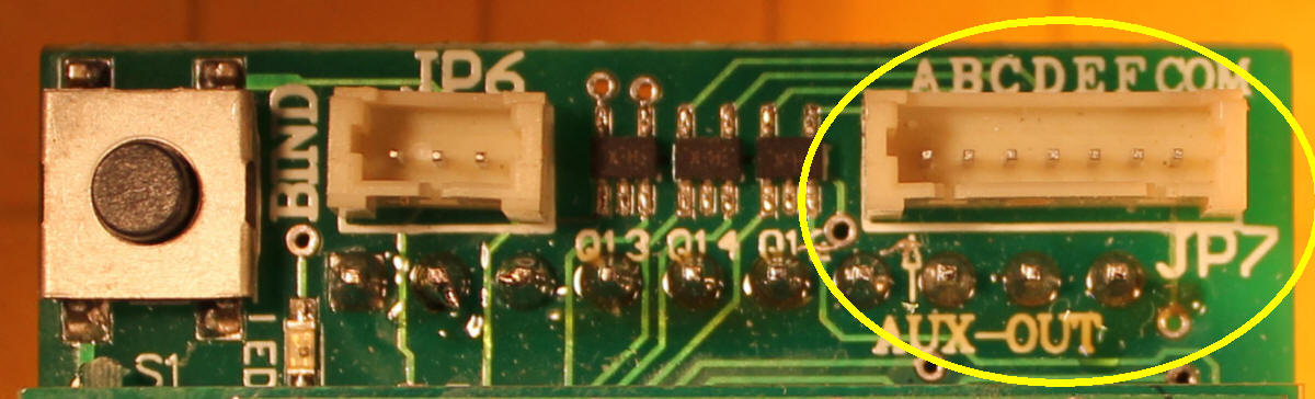
There is a seven pin header on Revolution receivers that is labeled "AUX OUT". Its pins are labeled "ABCDEF COM".
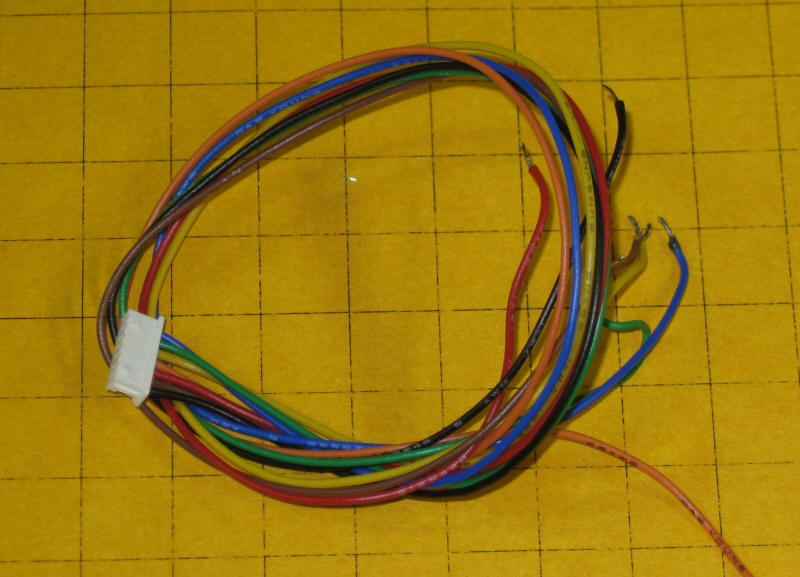
The cable that plugs into this header has seven wires colored black , brown, red, orange, yellow, green and blue. The black wire is the common or ground connection. The other wires correspond to outputs 1 through 6 and can be activated by pressing one of the buttons labeled 1 through 6 on the Revolution transmitter.
Open Collector Outputs
The Revolutions receiver outputs are referred to as open collector outputs. This means that electronically they are equivalent to NPN transistors. The control lead from the wiring harness is connected to the collector of a transistor whose emitter is attached to ground. When an auxiliary output is activated on the Revolution the control lead connects the output device to ground. This design works well but is limited by the amount of power that it can handle. The devices that connect to the outputs are seen at the left of this photo.
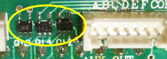
Note the "2X" markings on them. This was the only clue that I had to their identity.... it was great fun getting the data sheet for them! The devices on the receiver are dual chip transistors, similar to part # SUR521H. According to the data sheet each of the transistors is rated at 100 ma. I would not, however, connect a device that would draw anything near that level. It is best to keep the current draw to 20 or 30 ma, maximum.
Testing the Auxiliary Outputs
The simplest way to test the outputs is to connect each of them to an LED that can be turned on and off by the Revolution transmitter.
This schematic shows the wiring that is needed to connect to six LEDs to the six outputs. The ground connection, which goes to the COM terminal, should attach to the negative terminal of a 12 volt battery or power supply. The connection labeled +12v goes to the positive terminal of the power source. Each of the cathodes from the LEDs connects to the interface through a 1000 ohm current limiting resistor. All of the anodes are wired together and connected to positive 12 volts. (There is detailed information about LEDs and there use in another article, see LEDs 101)
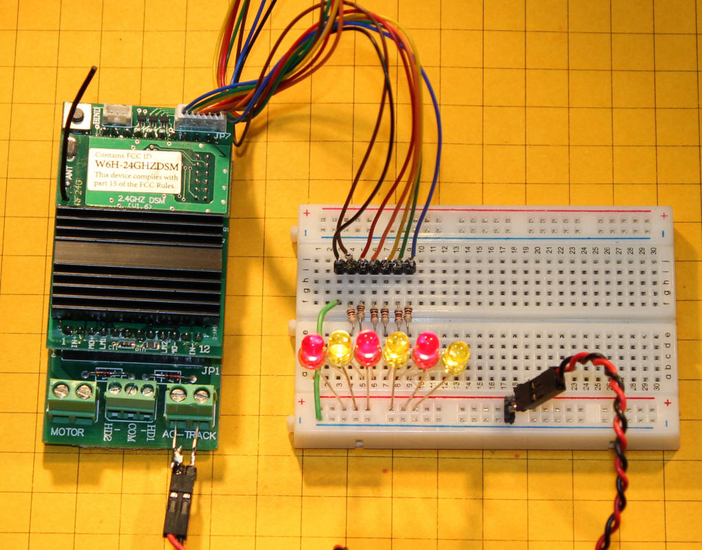
The photo shows the circuit above on a simple breadboard. The seven wires from the auxiliary interface plug into the breadboard with the black wire going to the negative buss and the colored leads going to the LEDs through six 1000 ohm resistors. The Revolution and the breadboard share the same power supply. The power cable going to the breadboard, the red and black twisted wires, is connected in parallel with the power wires that go to the Revolution.
Activating a Relay
If we had a relay that drew no more current than the LEDs used above we could just substitute relays for the LEDs and be done. Unfortunately things are not that simple. To activate a relay we need to deal with several things.
The circuit shown in the schematic below includes the components that are needed to operate a relay.
Q1 is a general purpose PNP transistor. I used a 2N3906 but many others would work, too, The base of the transistor connects to one of the auxiliary outputs through a 1K resistor. The emitter connects to the power that is being applied to the Revolution receiver. Resistor R2 provides bias voltage to the transistor's base.
Diode D1 protects the transistor from voltage spikes that are created when the magnetic field in the relay's coil collapses. The circuit will work without the diode but the transistor will fail after a short time if the diode is omitted.
Resistor R3 limits the amount of current that goes to the relay. If we are using a 12 volt relay and supply 20 volts to the Revolution we have to use an appropriate resistor to protect the relay. I used a 470 ohm resistor. This value was determined by measuring the current drawn by the relay when it operated at 12 volts. A 470 ohm resistor limited the current to the same value at 20 volts.
Adding a resistor is the simplest way to deal with using a relay with a coil that requires a lower voltage than what you have available but it may not be the best way. Calculating the appropriate resistor value can be a challenge and the resistor can get quite hot when the relay is active. A better alternative is discussed below.
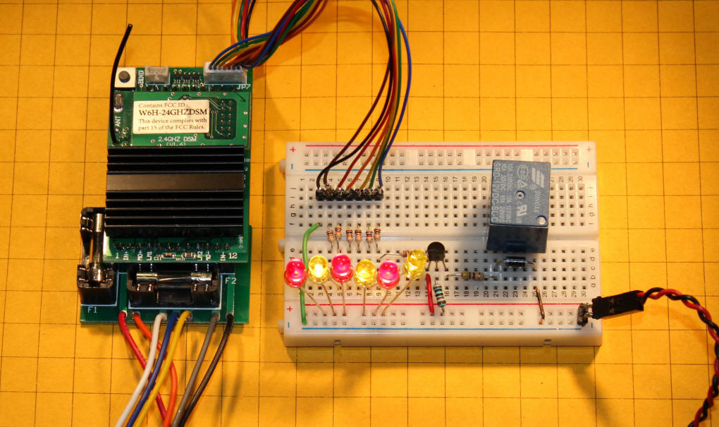
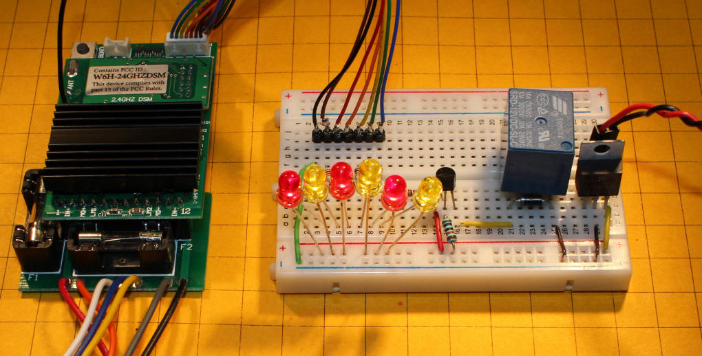
This photo shows the relay, the blue object to the right, the transistor, the small black device at the center of the board, the diode and the resistors that complete the circuit. This relay is connected to the LED that is activated by switch number 1. That is the one activated by the blue wire from the auxiliary connection. Five more relays could be added to the circuit by duplicating the same circuitry that is used here.
Adding a Voltage Regulator
A better way to lower the voltage that goes to the relay is to use a voltage regulator. If we are supplying 20 volts to the Revolution and we are using a 12 volt relay a 12 volt regulator such as a 7812 does a great job of providing the right voltage. Similarly a 7805 regulator can be used to supply 5 volts to a 5 volt relay. The regulator may get hot, too, but it is designed to dissipate heat and a heat sink can easily be added should it be needed.
Here is the breadboarded example. The voltage regulator, on the far right, takes the input power and delivers 12 volts to the board. Note that the 470 ohm resistor that once went from the transistor to the relay has been replaced by a yellow piece of wire as the resistor is no longer needed.
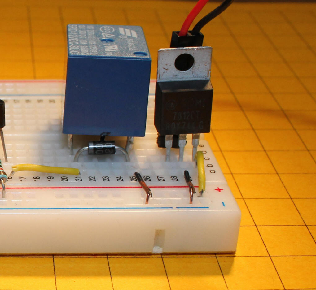
This close-up shows the connections to the 7812. The terminal to the left receives the input voltage from the track or batteries. The center terminal connects to ground. 12 volts is available at the terminal on the right and is connected to the positive terminal on the breadboard through the yellow wire at the right.
A Note About Using Track Power
If you are planning on using these circuits from track power you must make sure that the polarity (positive and negative connections) are correct. A bridge rectifier or a set of four diodes is needed. This article on using LEDs with track power goes in to detail about what needs to be done. The same concepts apply to these circuits.
http://www.trainelectronics.com/LED_Articles_2007/LED_102/index.htm
Give it a Try!
I hope that this overview of the auxiliary interface on the Revolution receiver provides you with enough information to experiment yourself. Keep in mind that the same circuits can be used to activate relays with the auxiliary output ports that are on many other radio control or DCC decoders. Most of them also use an open collector design.
Please let me know if you have any questions.
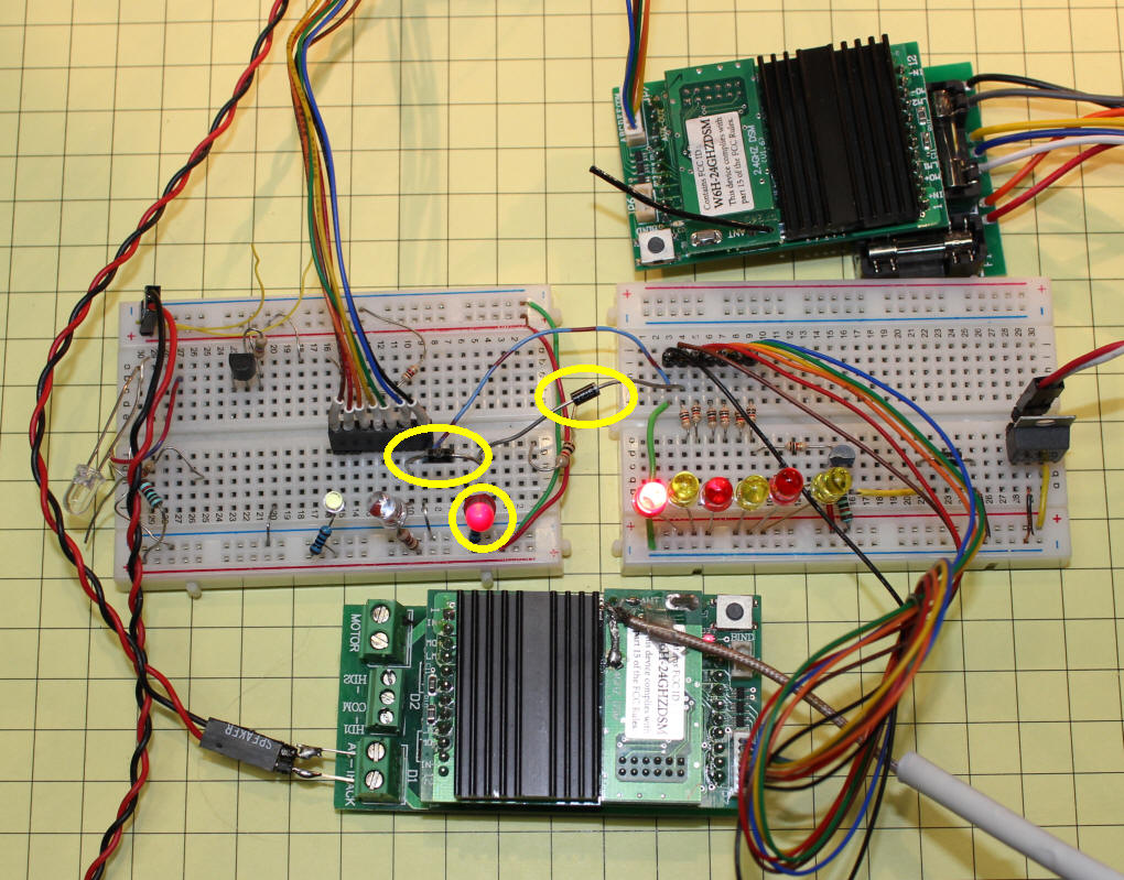
A question came up after the original article was written that involved being able to trigger a sound from either of two different Revolution receivers. The photo below shows how it can be done.
The board on the left is connected to the auxiliary interface on one receiver and the one on the right to the other. The red LED near the center of the photo (yellow circle) is connected to both the left and right boards via two small diodes (yellow ovals). Note that the bands on the diodes point towards the auxiliary interface wires. In this configuration either receiver can activate the LED.
For this test I used two separate power supplies for the receivers and it was necessary to connect the grounds of the two boards together. I did not test this with a sound card but don't see why it would not work as well as it does with the LED.
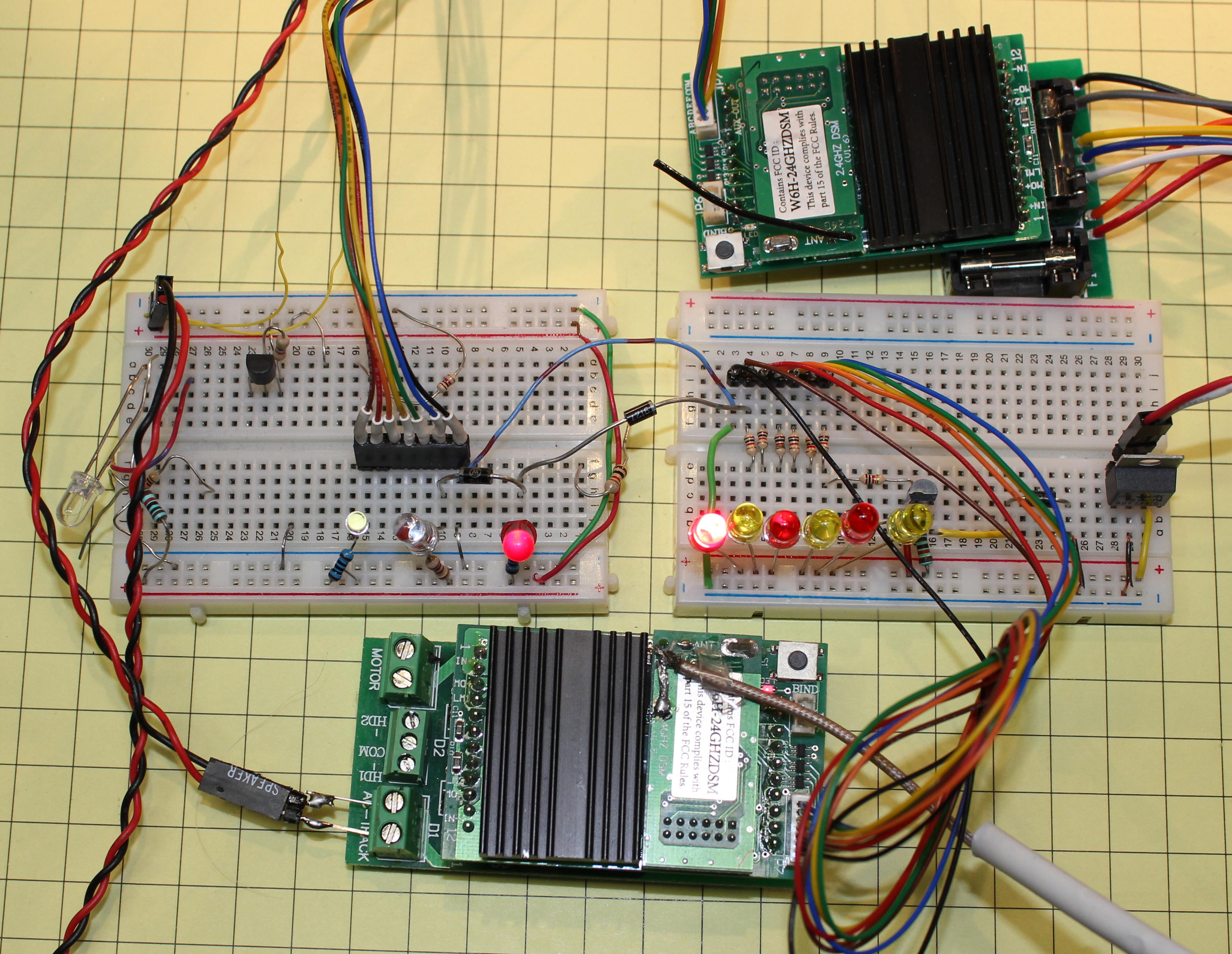
Click the thumbnail below for a higher resolution image of the circuit.
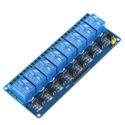
I recently came across an 8 relay board that is readily available from Amazon and eBay - just search either for
These relay boards are intended for use with Arduino, PICAXE or other microcontrollers but are well suited to other purposes such as using the Revolution's Auxiliary port to activate things with the relays. Each of the relays is connected to one of the 8 activation pins at the center of the board. They are labeled IN1 through IN8. The pin labeled GND connects to the negative power connection while the pin labeled VCC connects to plus 5 volts.
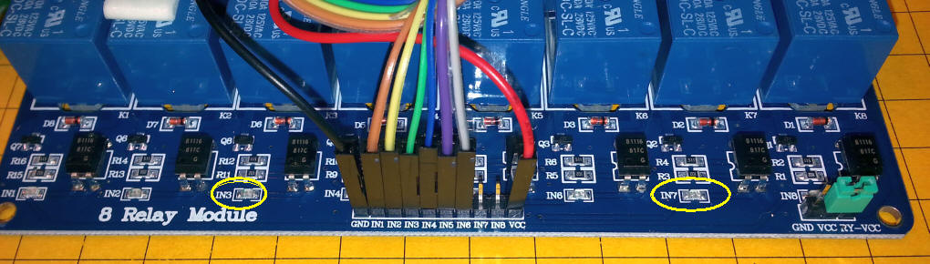
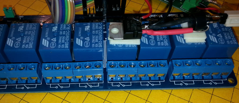
The black devices in front of each relay are opto-isolators that protect the activating device (the Revo in this case) from damage. There is also a small red LED (labeled IN1 through IN8 on the board) that lights when a relay is activated. Two of the LEDs have been circled below.
A source of 5 volts is needed to power the board. This could be provided by a battery or taken off of the power supplied to the Revolution. Since our trains run on voltages quite a bit higher than 5 volts a simple circuit is needed to step down the voltage. The connection that goes to the power input of the Revolution is connected to the two input pins of a bridge rectifier. This guarantees that DC power of the correct polarity is always present. The rectified voltage goes to a 7805 voltage regulator that provides 5 volts to the relay board. For more information about using circuits like this see: http://www.trainelectronics.com/artcles/voltage_regulator_article/
You may need to add a small heat sink (as described in the article referenced above) if you leave more than one or two relays active for any time as the 7805 may get quite hot!
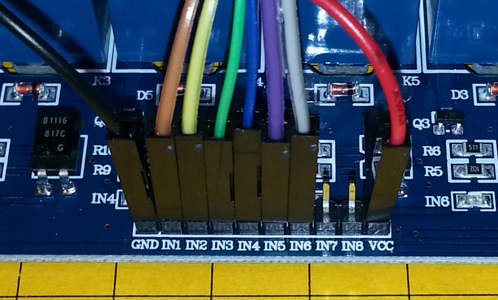
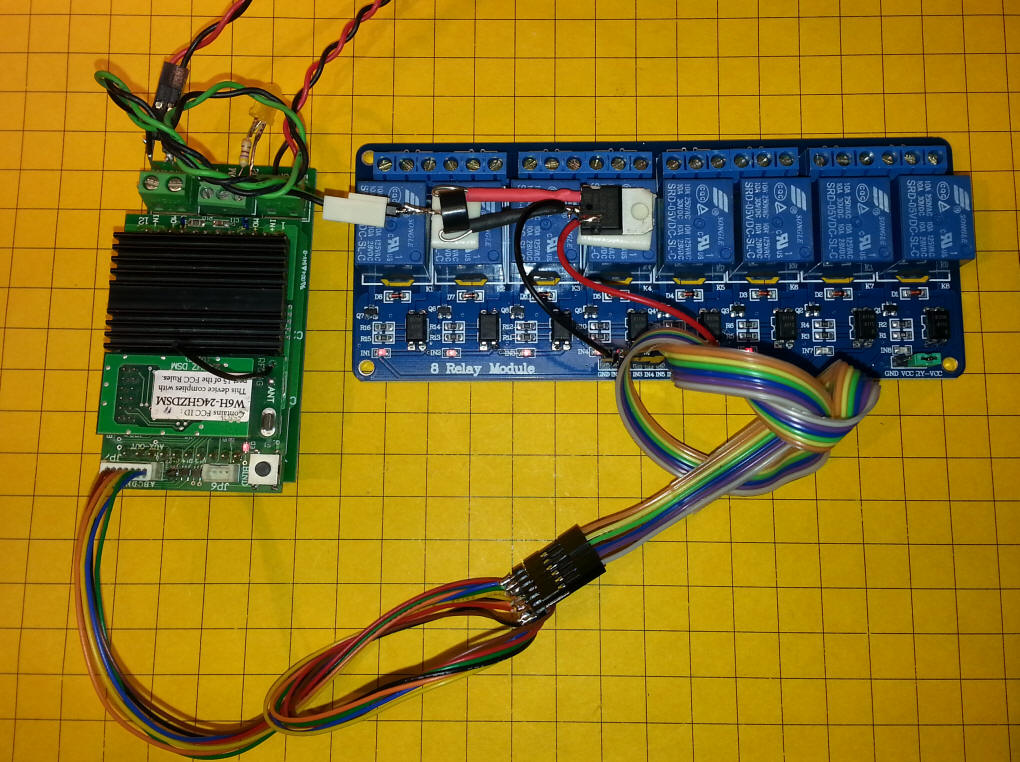
This photo shows the Revolution receiver connected to the relay board. The bridge rectifier and voltage regulator are attached to the tops of the relays with double sided tape. The green/black wires supply power to the bridge rectifier from the power input pins on the Revo. Pins 1 through 6 from the Revo's AUX output go to six of the input pins on the relay board. Note that the common connection on the AUX interface is not needed.
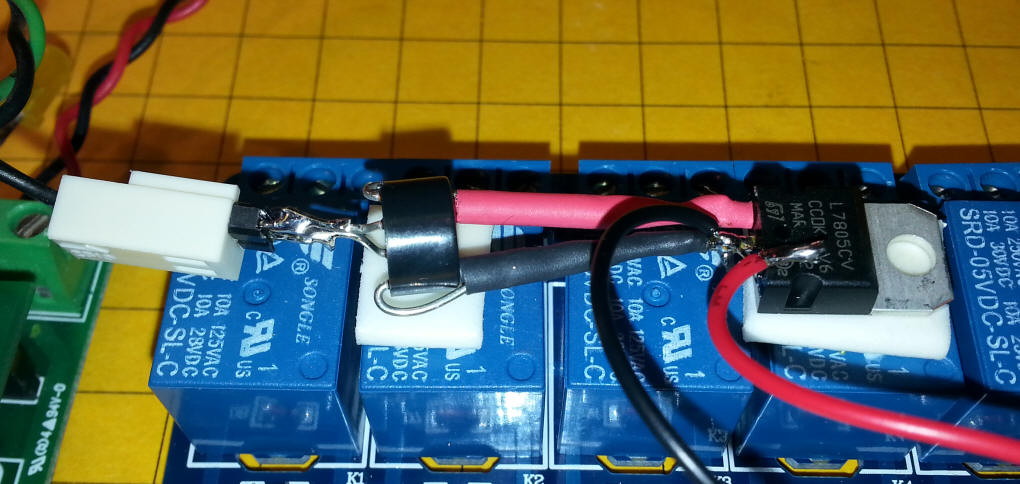
This close-up shows the bridge and 7805.
Each of the relays is a SPDT (single pole, double throw) that has its contacts connected to a 3 pin connector.
Although I have not tested it with other controllers I would think that this
relay board would work with most or all DCC controllers.
Please let me know if you have any questions of comments.