Thermistors, the Magic Behind Smooth Acceleration
revised 11-20-07
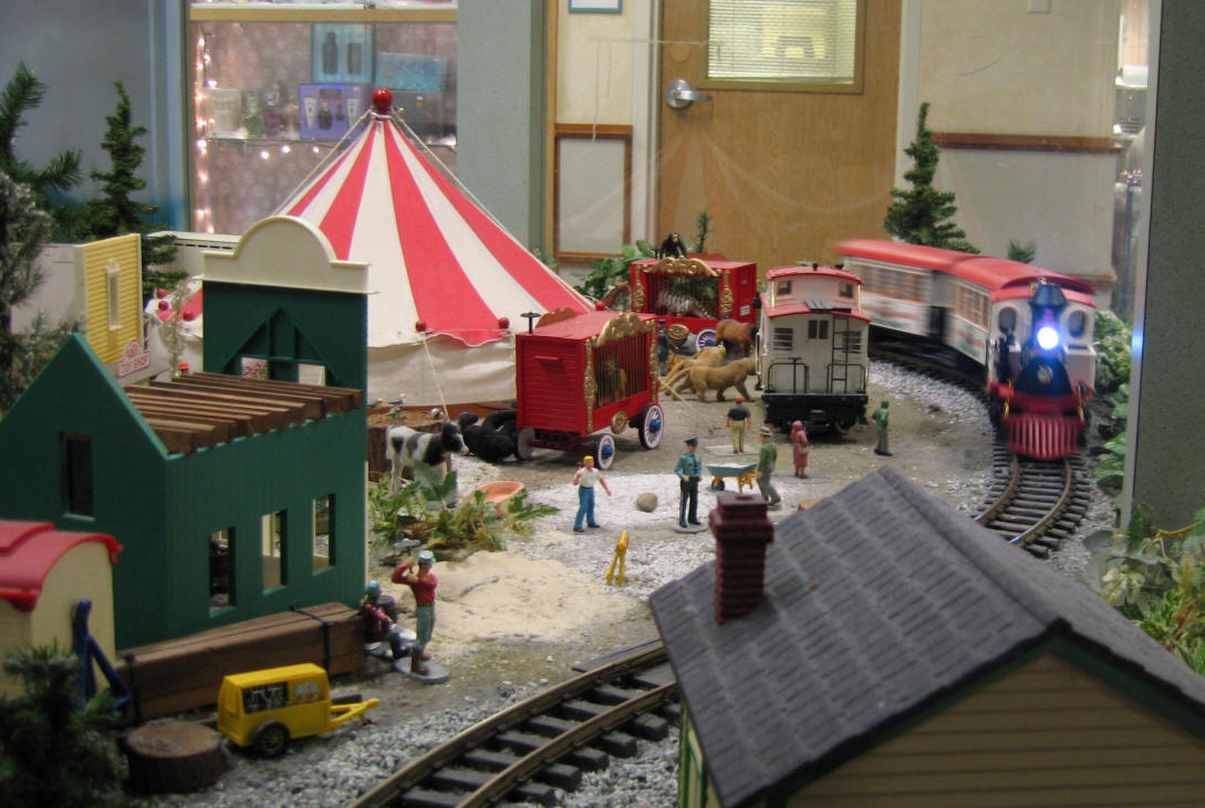
In the first part of this article we were working with an automated train layout that is installed at Pittsburgh's Children's Hospital. It is controlled by a timer that runs the train for a fixed interval each time a button is pressed. Unfortunately, this system caused the train to jerk to a start when full power was applied and screech to a stop when power was removed. Installation of a pair of large capacitors took care of bringing the train to a much smoother and more realistic stop but I was not completely satisfied with the rate of acceleration provided by the capacitor. Since capacitors charge rather quickly the train still started up too rapidly.
Once again I went to the vast well of "Ham Radio Wisdom" and discussed my disappointment with the acceleration provided by the final design. A fellow ham recalled that there was a device that he worked with when doing TV repair that was designed to limit the surge of current that entered the set when the TV was first turned on. This sudden burst of full power that was introduced to the set at startup had the potential to damage the set and its power supply. He thought it was some type of thermistor but didn't recall much more about it.
WHAT THE HECK IS A "NEGATIVE TEMPERATURE COEFFICIENT" THERMISTOR?
That was enough to get me started on Google and within minutes I had tracked down the device he had described. It is called an "Inrush Current Limiter" and is a specialized type of thermistor. You may know that a thermistor is a device that changes resistance as its temperature changes. If you have an inexpensive digital thermometer chances are good that the sensor on that device is a thermistor. Most thermistors have a higher resistance as their temperature increases. In our application, however, we need what is called a Negative Temperature Coefficient Thermistor (NTC) that presents less resistance to the circuit as it becomes hotter.
The theory behind using these devices to slow the acceleration of our train is simple. The thermistors I chose have a resistance at room temperature of 20 ohms. When power is turned on the train starts out very slowly since much of the power from the transformer is being absorbed by the thermistor. This power must be dissipated and serves to heat up the thermistor lowering its resistance. As it heats up the resistance drops, more current flows to the motor and the train speeds up. Just what we wanted!
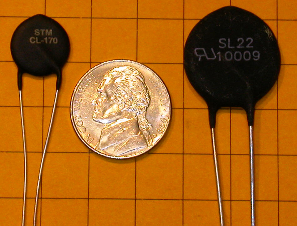
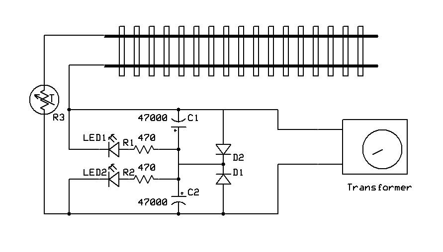
You may recall that I was looking for simple devices to use on the Children's Hospital layout. This one certainly fit the bill! It is about the size of a nickel and has two wires coming out of it. To install it in the circuit that was described in the first part of this article you simply disconnect one of the wires going to the track and place the thermistor in series with that connection. In the schematic below the thermistor is labeled R3.
TESTING & RESULTS
I put together a 5' diameter loop of track for testing. Without the thermistor the train reached its top speed within a fraction of a second and maintained that speed until the power was removed. With the thermistor in the circuit the engine started out very slowly and didn't achieve top speed for 30 or 40 seconds. This was certainly gradual acceleration!
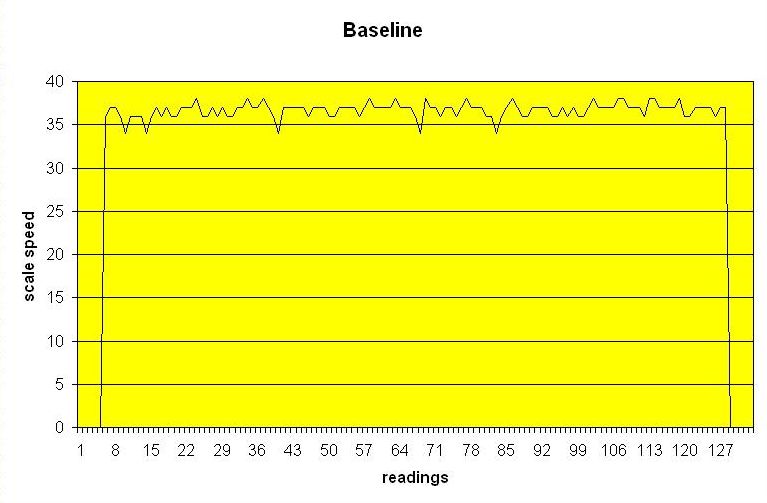
The first graph is of a 120 second run without any additional circuitry. The power goes on, the train goes to top speed, continues for 120 seconds then goes off stopping immediately. This graph is representative of what happened at the Children's Hospital layout before any modifications were made. Note the nearly vertical lines at each end indicating rapid, almost instantaneous, speed changes. The speed is recorded a little more frequently than once per second.
CAPACITOR ONLY
This graph is of a 120 second run with a 47,000 mf capacitor in parallel with the track power supply. This circuit was discussed in great detail in the first part of this article. You will note that the acceleration is almost instantaneous but that it takes a few seconds to stop completely when power is removed.
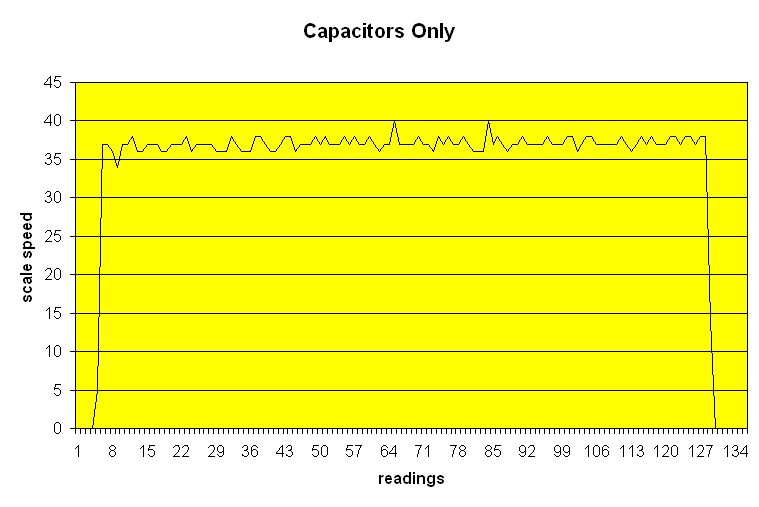
It may not be clear in the full graph above but the detail below, showing just the last few seconds of readings, illustrates that the train does not come to a screeching halt, but slows over a period of few seconds.
|
As you look at these graphs I hope you are wondering how I gathered this data on the train's speed! Make sure you check out the speedometer described here: http://www.trainelectronics.com/speedometer/speedometer_manual.htm\ It uses a train's passing between a pair of infrared light beams to compute and display scale speed. Surely that device wouldn't provide sufficient data for a good graph as it only computes speed once for every lap of the track. The good news is that since I first wrote about the speedometer it has been modified to wirelessly transmit continuous, real time speed information from a moving train. I hope to have this unit ready for market in the near future but for now it does a great job of helping out with this analysis! |
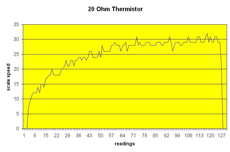
CAPACITOR & 20 OHM THERMISTOR
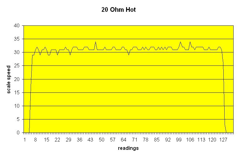
Here is another 120 second run with both the capacitor in parallel with the track power and with a 20 ohm thermistor in series with the track power. Note the slow, steady acceleration and that the train never reaches the same top speed as it did in the examples above. This is due to the thermistor still inserting some resistance into the circuit even once it warms up.
TYPES OF THERMISTORS
Thermistors come in a number of sizes with many different resistance characteristics. Pictured below are several thermistors from two different manufacturers. Their resistance ranges from 10 to 30 ohms.
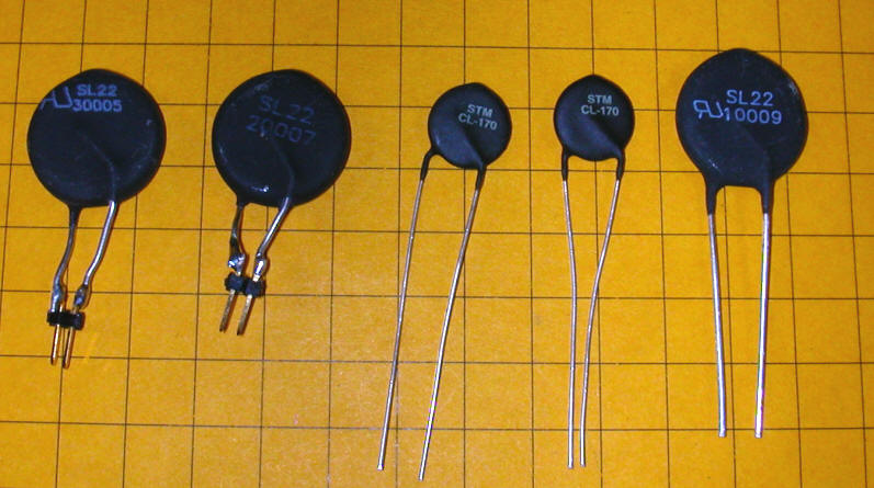
In order to get the most realistic and noticeable acceleration effect the resistance of the thermistor must be appropriate for the amount of current drawn by your engine. I have done a good bit of experimenting and found that most smaller engines, like LGB's 0-4-0 switchers and AristoCraft's Eggliner, work well with 20 to 30 ohm thermistors. Larger engines, like Bachmann's large center cab switcher, work well with a smaller resistance thermistor, say 10 to 15 ohms.
A PROBLEM WITH THERMISTORS
I am sure that some of you have picked up on one potential problem with the use of thermistors to slow the acceleration of a train engine. The full thermistor effect is only available if it is allowed to cool to near room temperature each time the train stops. I am sure that you can imagine that starting up with a thermistor that is still hot from a pervious run will greatly diminish its effect on the initial speed of the engine. This is illustrated when you compare the graph above and the one below, showing a second run without allowing any time for the thermistor to cool.
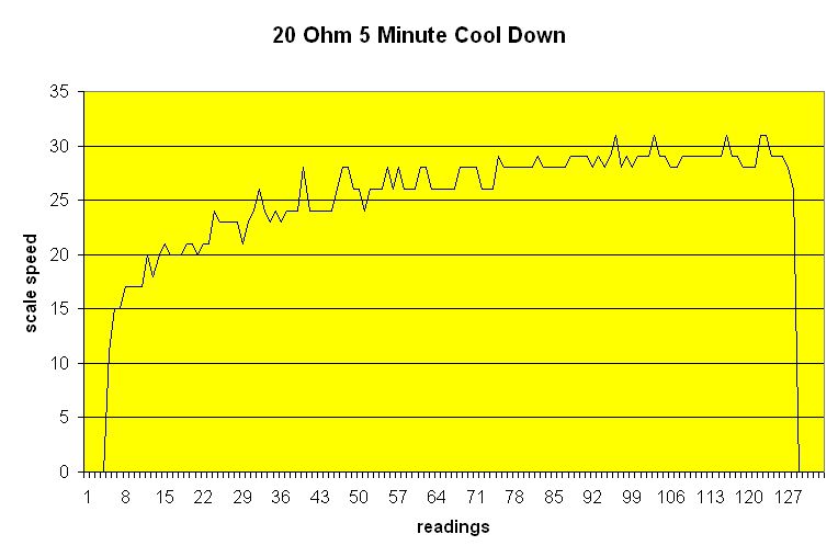
The next graph shows the same engine running after allowing a 5 minute cool down period. It does not accelerate as gradually as when completely cool but it is still very noticeable. One way around this is described later on in the article where two thermistors and two diodes share the work.
USE WITH LARGER ENGINES
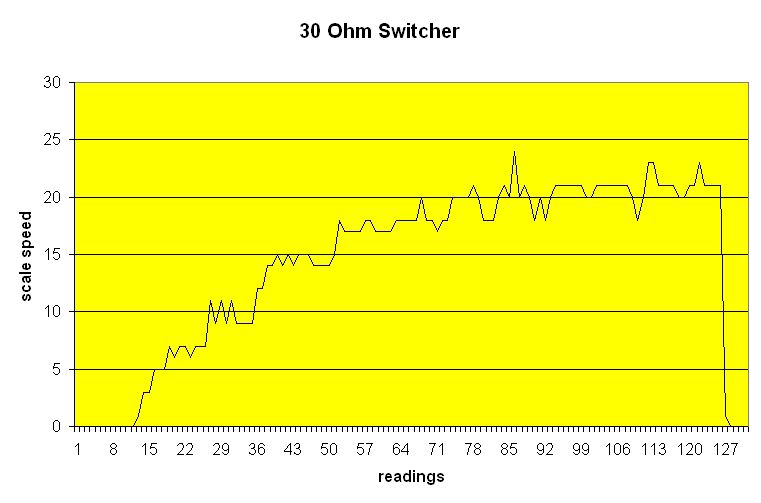
All of the tests above were done with a small LGB 0-4-0 switcher. Larger engines react differently to the thermistor. Below is a plot of the acceleration of a Bachmann Center Cab Switcher, a large narrow-gauge engine with two motors. The engine didn't even start moving at all when power was first applied. The 30 ohm thermistor had to heat a bit before enough current cold pass to get the motors spinning. That is why the first 10 or 12 readings are zero scale miles per hour.
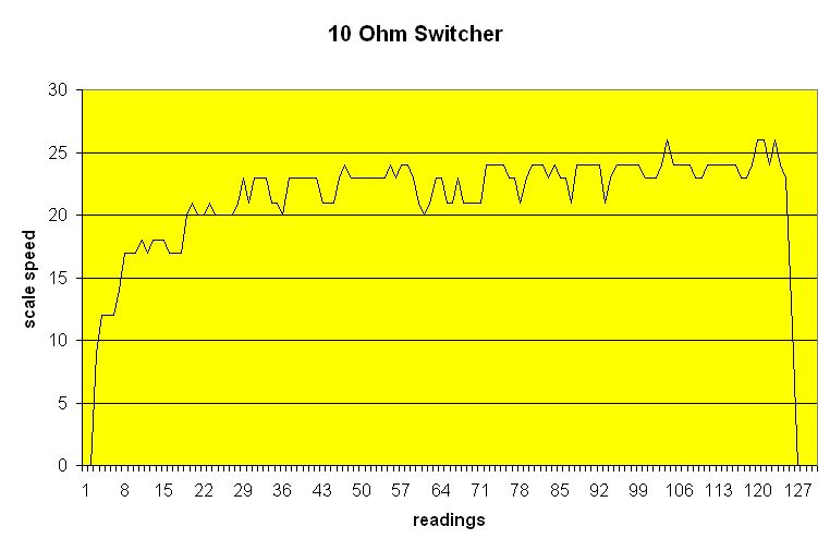
Here is the same engine with a 10 ohm thermistor. Much faster acceleration but still a very noticeable effect.
The two capacitors and a thermistor are doing a great job with the Children's Hospital train. It now starts out smoothly and decelerates at a much more realistic rate than it did when I first saw it. Even more importantly, the devices that are being used are designed for long term, low maintenance duty. Cooling of the thermistor is not a big issue since the train is frequently sitting for a significant amount of time between runs.
HOW OFTEN IS THE TRAIN RUN?
The information below was gathered by another new addition to the Children's Hospital layout. As soon as I saw the train I was curious about how often children (and adults?) were pressing the START button. To answer that question I wired an old laptop up to the control system and programmed it to log the date and time whenever the train was activated. The graph below shows a single diamond each time the train ran over a 2 week period in mid-December. To save you from counting each one there are almost 1300 entries, nearly 100 train activations each day! The other surprising thing about this graph is that is shows activations at all hours of the day. Surely children are not the only ones enjoying the trains! It is also apparent that the thermistor was allowed to cool on many occasions.
OTHER APPLICATIONS
After completing the work on this application I started giving thought to other places where the capacitor and/or thermistor would be of value. One use for the capacitors was described in the first part of this article, using on-board capacitors to give an engine a little assist in crossing dirty track. Another logical application is with a point-to-point rail line such as those that many of us use for trolleys or small engines.
USE WITH A POINT-TO-POINT RAILWAY
If you have space for the capacitors in a trolley or other train that runs on a point-to-point railway this is a great way to guarantee smooth acceleration and deceleration at each end of the track. For those of you who have not worked with such a layout a brief description is in order.
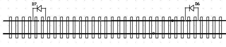
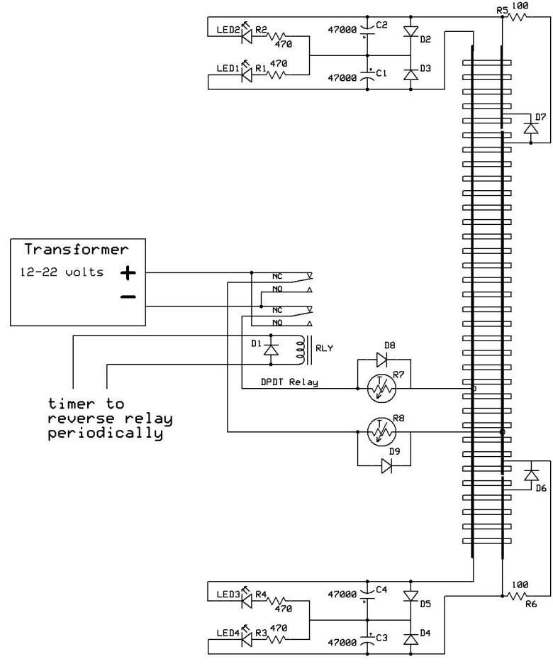
In a point-to-point layout you have a single run of track and the train goes back and forth on it. One rail of the track has a cut section in it at each end. A diode bridges the gap in the track and cuts power to the engine when it enters the cut section. A reversing controller of some sort periodically toggles a DPDT relay and reverses the polarity of the track. When this happens the diode conducts and the train goes to the other end of the track. You can see the cut sections and diodes in the illustration below. The placement of the diodes is critical. The bar on the diode must be oriented as shown below or it will not work properly.
I have experimented with this setup using only a simple timer to periodically reverse the polarity on the track thus reversing the direction of the train. The setup is very straight forward. A simple circuit with a small microprocessor controls whether a double pole double throw (DPDT) relay is open or closed. The relay is wired in such a way that it delivers the power from the transformer with polarity in one orientation if it is open and the opposite way if it is closed. In other words, if the relay is open the train runs in one direction. If it is closed it runs in the other. The microprocessor has only one other connection, a potentiometer or volume control, that adjust the amount of time that passes between the relay being toggled between its two states, open & closed. The delay time is set to a period long enough for the engine to go from end to end and pause for a minute or so between runs.
POINT-TO-POINT WITH ON BOARD CAPACITORS & THERMISTOR
The thermistor and two capacitors are placed on the engine or a trailing car so that the thermistor retards acceleration and the capacitors gradually bring the engine to a full stop once the diodes are passed.
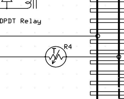
The schematic below shows the connections and details of how the relay is wired. The devices at the top, the motor, thermistor, LEDs, resistors, diodes and capacitors, are mounted on an engine or a trailing car. The reversing unit and double pole double throw relay are trackside.
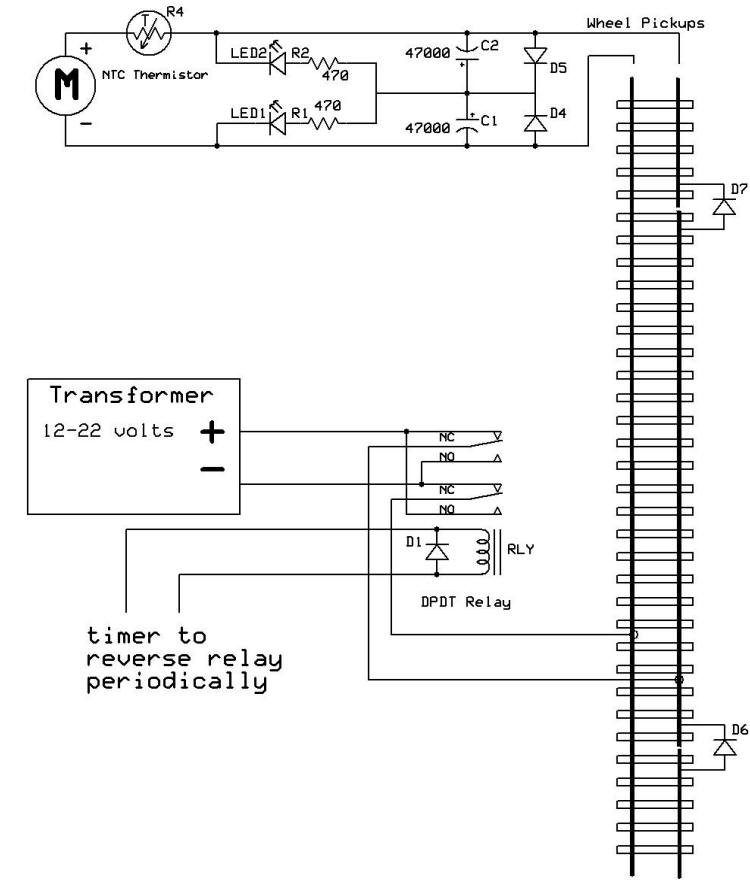
If you cannot easily insert the thermistor in series with one of the motor's leads as shown in the schematic, the thermistor can be put in series with one of the leads providing power to the track. Electrically there is no difference and it is much easier to cut wires by the track than inside of an engine!
Most point-to-point railways have only a short length of track, perhaps 2 or 3 feet, beyond the diodes at each end. Since the train has the potential to travel a good distance beyond the diodes as it operates on the capacitor's power additional track may be needed at each end.
POINT-TO-POINT WITHOUT ENGINE MODIFICATIONS
It is also possible to use the capacitors and thermistor in a point-to-point layout without any modifications to an engine. You will need two of the non-polarized capacitor pairs that were described in part one, two thermistors and two diodes. All of the components can be attached to the track as shown in the schematic below. Please make sure that resistors R5 and R6 are rated for at least 5 watts as they must dissipate a good bit of heat. If you use standard 1/4 watt resistors from Radio Shack you are sure to burn them out in short order. The dual thermistors and diodes that bypass them are there so that only one thermistor is used for each direction of travel. This allows more time for cooling between runs and works very well.
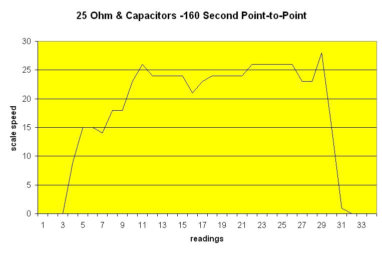
The graph below shows the point-to-point railway operating with a pair of 25 ohm thermistors and a pair of capacitors at each end of the track.
REVERSING UNIT
A number of manufacturers, including LGB and AristoCraft, sell reversing units. Being one who likes to have complete control over how things operate I designed and built my own. It is an extremely basic device that has four primary components, an indicator LED, a DPDT relay, a PIC microprocessor and a potentiometer to adjust time ranges. The timer is simply inserted between the two transformer leads and the track. The potentiometer is adjusted to select a delay time from a few seconds to 40+ minutes. After the time period has elapsed the relay is toggled so that the track voltage is reversed. The prototype is pictured below.
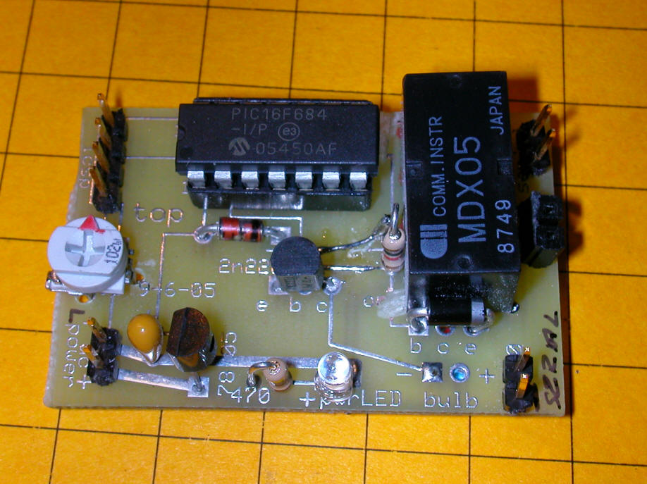
If there is sufficient interest I would be happy to write an article giving details on the construction and make kits and complete units available to readers.
If you share my interest in tinkering with electronics and garden trains give this a try and let me know how it works for you!
| A note about using PWM with these circuits: As you know, some model train power supplies use PWM (Pulse Width Modulation) to adjust the voltage applied to the track. I have tested these circuits with straight DC power supplies and with a MRC Control Master 20 power supply that uses PWM. Both worked well but the capacitors may work against the PWM power supply as they try to even out the voltage that is applied. My recommendation is to do any initial experimentation with a traditional, non-PWM power supply before testing with PWM. |
NTC Thermistors are available from a many distributors, including Digikey. I have a number of different value thermistors available for $2.00 to $3.00 each + shipping should you like to experiment a bit. Please contact me via email at dave@davebodnar.com for details.