A New Incline in Pittsburgh
Christmas 2005
Revised 12-28-05
Ever since we moved into our new home in 2002 I have had some sort of railroad related display in the front of the house for Christmas. The first year it was a simple point-to-point trolley that ran on the railings of the front porch. The second year that trolley line was extended quite a bit so that it ran from the front porch around the side of the house to the side porch and back. Last year it was a figure 8 track running a Christmas train complete with an illuminated Santa on a flatcar.
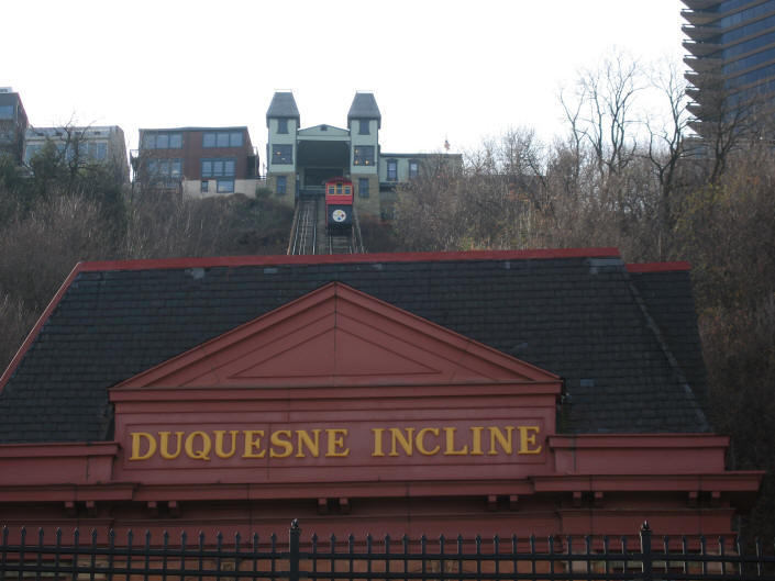
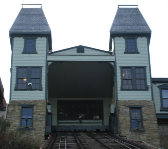
This year I decided to try something totally different. I have always been fascinated by Pittsburgh’s two remaining inclines, the Duquesne Incline and the Monongahela Incline. They are the last of fifty inclines that once ran up and down the hills around the city. After doing some research I decided that a model of the Duquesne Incline would be an appropriate holiday display.
LOCATION
At first I planned to run the incline’s track up the hill that connects our
driveway and the front yard. Unfortunately that hillside was fairly short and
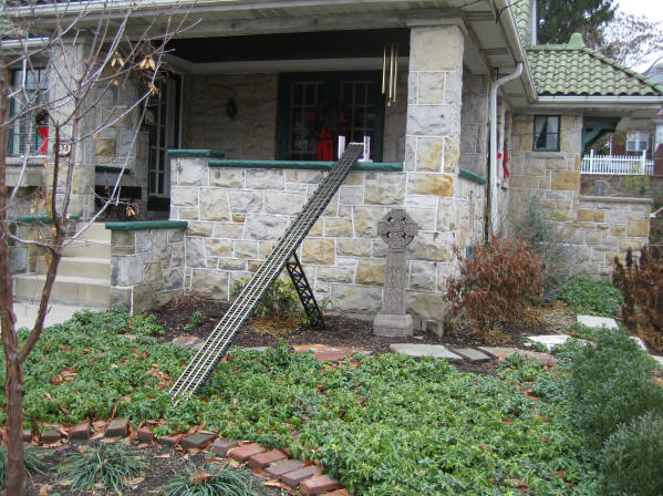
wouldn’t be very visible to the folks passing by. The most visible location was
between the front yard and the top of the stone railing that surrounds our front
porch. The Duquesne Incline is tilted at just a hair over 30 degrees. A similar
run from the porch to the yard came to 13 feet of track, a reasonable
length.
TRACK
Time was quite an issue since I didn’t get started on this project until just
before Thanksgiving and I wanted it to be running on December 1. For this reason
I had to make some compromises. The first was to use standard AristoCraft track
rather than hand laid rail. Since the gauge on the real incline is 5 feet
between rails the scale of my model incline had to be 1:34 since I was using 45
mm gauge track. I would have preferred using wider gauge track so that the scale
would have been closer to 1:24 or 1:20. Maybe for next year!
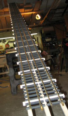
The design of the track and support structure closely mirrors that of the Duquesne Incline which has two cars running on two parallel tracks. This allows one car to go up as the other goes down. More importantly one car’s weight balances the weight of the other car allowing inclines to operate with a fairly light duty power system.
The track supports for my incline consist of three main “beams” constructed of ¾” x 8’ strips of wood joined together and reinforced with ½” aluminum angle stock. The joints in the wood, needed to reach the 13' length, are staggered as are the joints in the aluminum. The aluminum was purchased in 8’ sections from Home Depot and the ¾” pine strips were ripped from larger clear pine boards on my table saw.
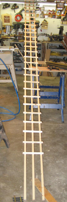
½” x ½” x 6” horizontal supports were nailed to the main beams with 1 ½” staples. If you haven’t purchased a nail / staple gun yet this project may be a good reason. It is safe to say that I saved hours on construction of the track supports by employing a nail / staple gun over using regular nails, screws or glue. It’s great fun, too! I used the track to help me place the supports as the fit nicely between the ties in the narrow gauge track.
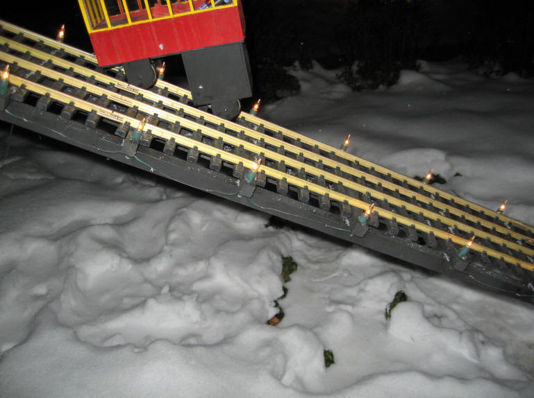
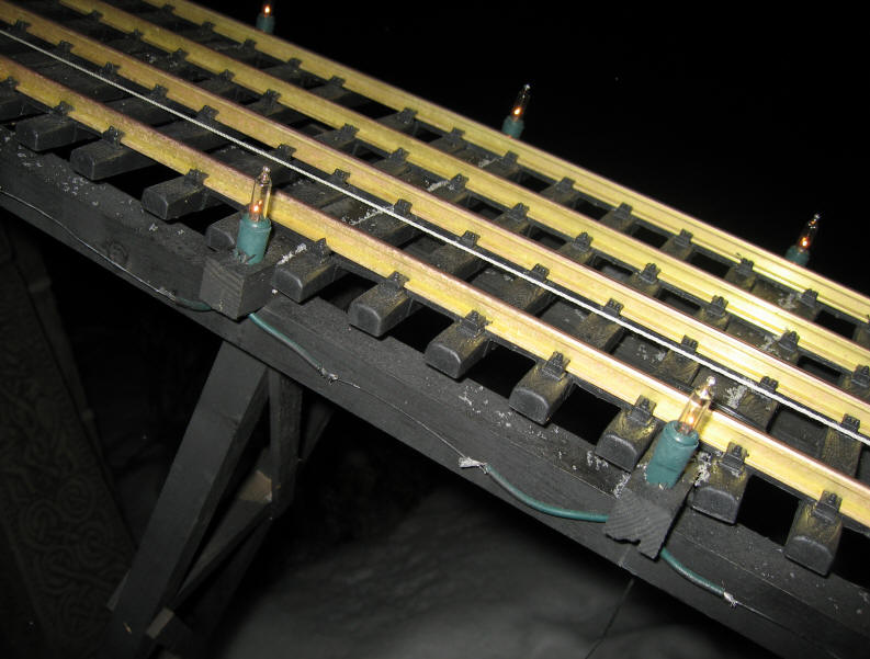
TRACK LIGHTING
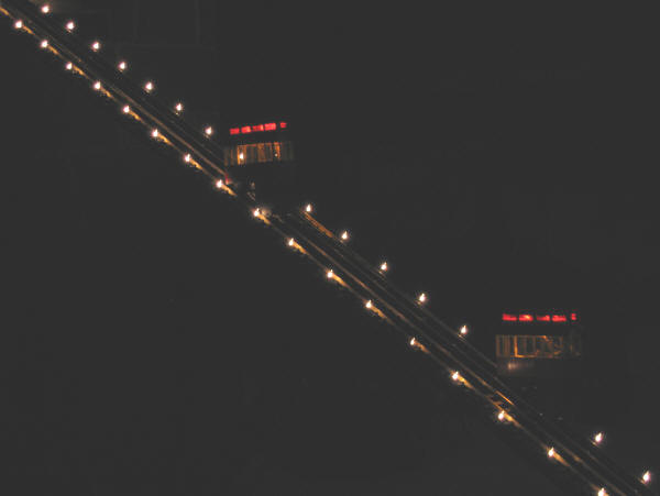
The Duquesne Incline has lights running down the sides of the track that really
show it off at night. My first thought for duplicating this on my incline was to
use LEDs. Unfortunately, bright LEDs cost $.50 or more each and I figured that I
would need more than 25 lights on each side. After doing a quick computation I
decided that LEDs might not be the best solution. Incandescent Christmas lights seemed to be
a logical alternative but I didn’t like the idea of running 120 volts up and
down my track. I also discovered that none of the lighting sets that were
available locally had the bulbs spaced the right distance apart. The solution was to cut
the individual bulbs
from strings of lights and rewire them so that the voltage was reduced and the
spacing was what I wanted. A tedious task but one that worked out well.
I cut 56 bulbs from a string of 100. A quick test with a variable output power supply showed that a single bulb burned nicely when a bit over 2 volts was applied to it. I had on old 17 volt AC transformer that I could use so I wired groups of 8 lights in series. This provided a little more than 2 volts to each bulb. Since I needed a total of 56 bulbs 7 sets of 8 bulbs were wired together. I drilled holes in the ends of the cross braces to hold the sockets for the individual bulbs and soldered jumpers between them to complete the circuit. When the wiring was done I spray painted the wires and solder joints making them all but invisible.
CARS
I was unable to find measured drawings of any of the components of the Duquesne
Incline. A field trip to Pittsburgh and ride up and down the incline provided me
with a few dozen photos that I was able to use to design the cars.
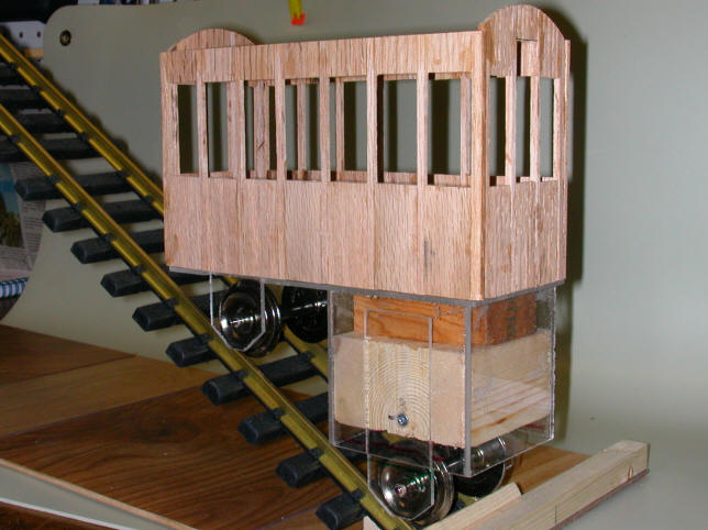
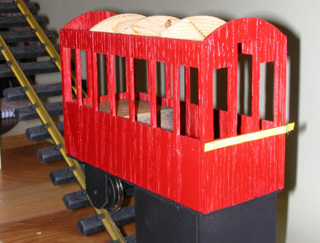
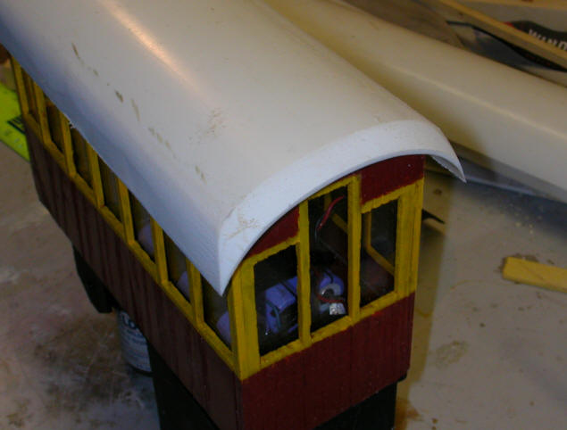
The base of each car is a wooden platform that is 2.4” x 6”. To keep this platform horizontal while riding on a 30 degree track a large compartment is under back end of the car. This compartment was once used for baggage and other cargo. In my model it measures 2.4” x 2.4”. In the photo below you can see a mock up of the car that I made from wood and Plexiglas.
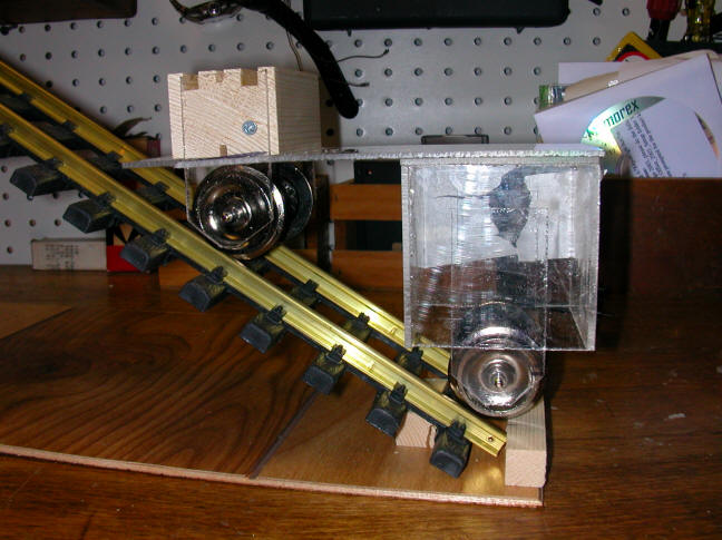
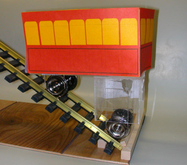
I used standard metal wheel sets for the trucks. They are held to the base with Plexiglas that is screwed to the wood base of each car.
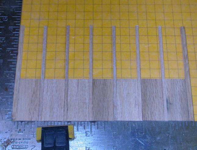
Each car body was built up from individual pieces of oak that I ripped from oak stock on my band saw. As you can see from the photo each side is made up of 22 pieces that are glued together. Each side has 10 pieces. The sections were glued together with TiteBond III glue. The parts were place on wax paper over graph paper. This kept things from sticking and the graph paper along with the carpenter’s square that I clamped to my work table helped to keep the sections square.
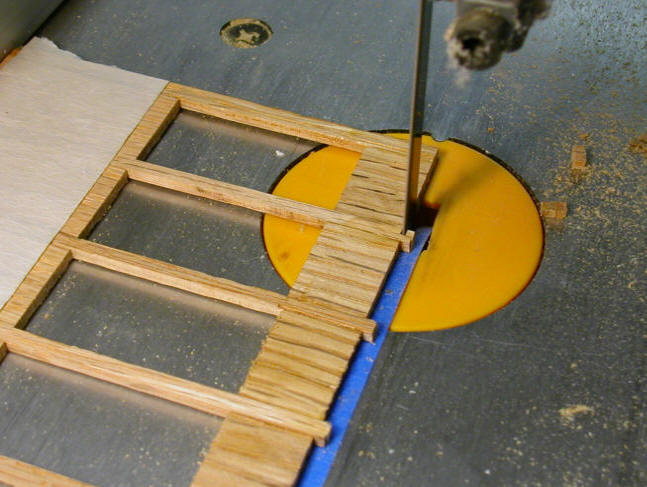
The band saw was used to trim the bottom and top of each side. Note the white tape that helped to hold the sides pieces together securely as the glue dried.
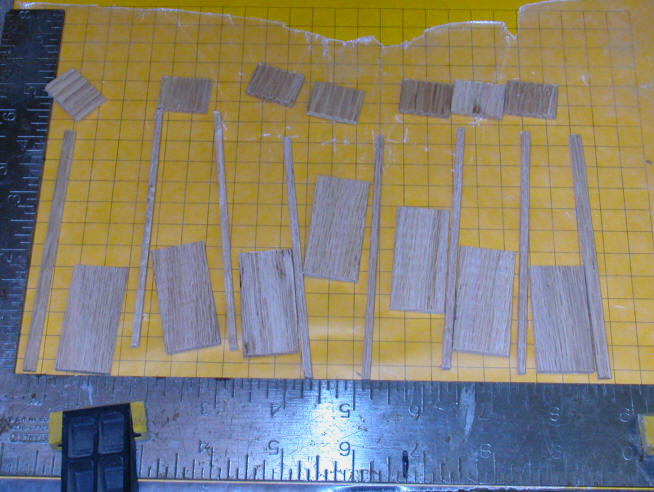
The parts below will make up the ends for each car.
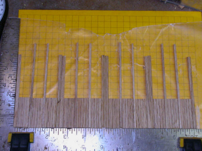
If you are thinking that it was a lot of work to glue the cars up from so many pieces think of the problems associated with cutting 20 windows into each car if the sides were made up from solid pieces!
After all of the glue dried thoroughly I trimmed the sides with the band saw. I also used the band saw to cut the curved tops of the car ends. The cars were glued together and lightly sanded.
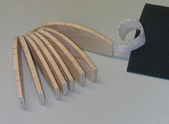
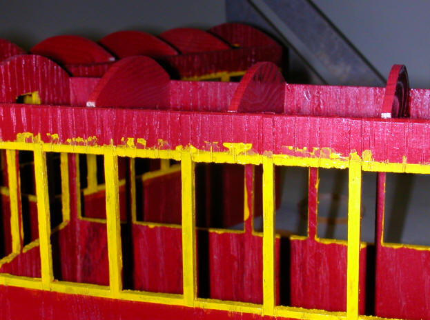
Curved roof braces were cut to match the curves on the end of each car. I taped 6 pieces of wood together and cut them as a group. This speeded things up and insured that all 6 pieces would be the same.
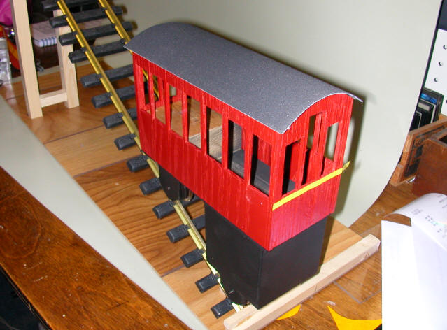
The roof was made from 4 ½” x 6 ½” piece of heavy emery paper. This type of sandpaper is sometimes called “wet & dry” sandpaper since it can be used to wet sand paint. It has a heavy cloth backing that I thought would hold up well to the winter weather. An additional set of curved braces were glued to the roof material to hold it at the appropriate curve. The finished roof was painted black on the outside and white on the inside.
Masking tape was used to paint the windows. I should have known better with an open grain wood like oak. To fix the damage while still matching the red sprayed body color I sprayed paint into the cap and applied it with a brush to remove (most of) the bleed over.
CAR LIGHTING
To make the cars more visible at night I added battery operated LED lights to
each car. I had considered getting power for the lights from the track but opted
for a simpler method that wouldn’t require me to add pickups to each wheel.
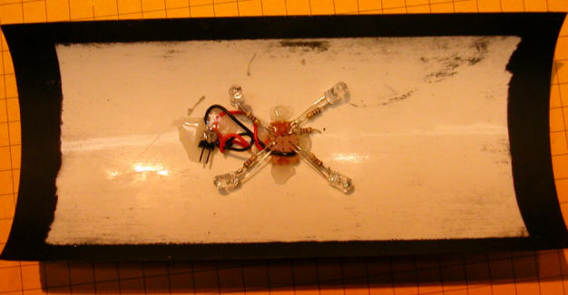
There are 4 amber LEDs in the ceiling of each car. They are powered by three 1.2
volt NiMH cells wired in series. This power source and a 200 ohm current
limiting resistor on each LED gives bright illumination and enough power allow
me to recharge just every other day.
MOTOR POWER
Up to this point I had given a lot of thought to how the incline would be
powered but hadn’t settled on a final design. I knew that I would need a small
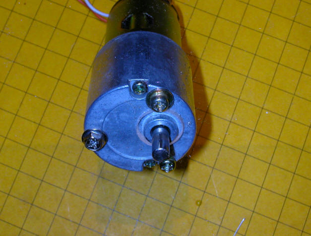
electric motor that was geared to turn at a very low speed. A number of the
vendors that I deal with sell what I was looking for. I ordered one from Marlin P. Jones
(MPJA.COM)
that would rotate at about 6 revolutions per minute when running on 12 volts.
My first design had the motor turning a large drum made of 4" plastic pipe. As the motor rotated the drum the cable from one car would wind around the drum while the other car's cable would unwind as it would be wound in the opposite direction. When the drum rotated this would have one cable reel in while the other reeled out. I was ready to build and test this design when a friend suggested just using a single large wheel in place of the drum. His thought was to have a single cable, not two as I had proposed. This single cable would be wound around the wheel so that one side would be pulled in while the other side was fed out. Even though this was not like the system on the prototype it sounded simpler to me and I had an old wheel salvaged from a robotic project so I gave it a try.
In this photo you see the wheel, which is about 5" in diameter, screwed to a wooden disk, In the center of the disk I used epoxy to attach a gear that fits the shaft on the motor.
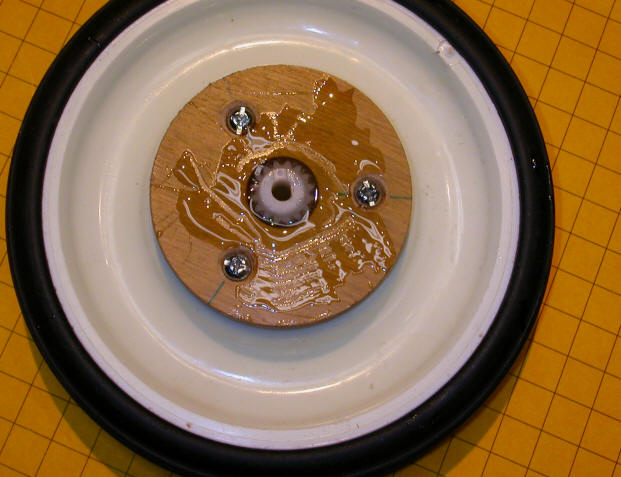
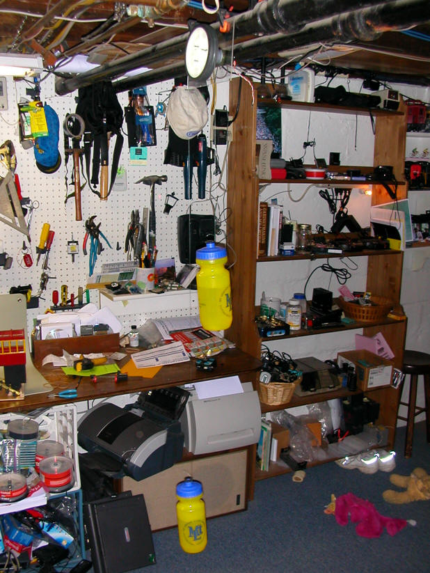
Before getting in too far with this power system I experimented to make sure the motor had sufficient power to move the cars. I hung the motor and drive wheel from my basement ceiling and attached two ½ filled water bottles to the ends of a line to simulate the weight of two incline cars. The wheel has grooves in it that make up its tread. The line fit nicely into one of the grooves. It had no trouble lifting one as it lowered the other so work continued on the track mounted system.
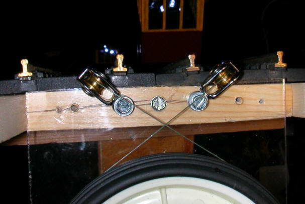
The wheel was placed at the upper end of the track between and below the
track. Two small pulleys were installed at the center of each track to direct
the “cable” towards the drive wheel.
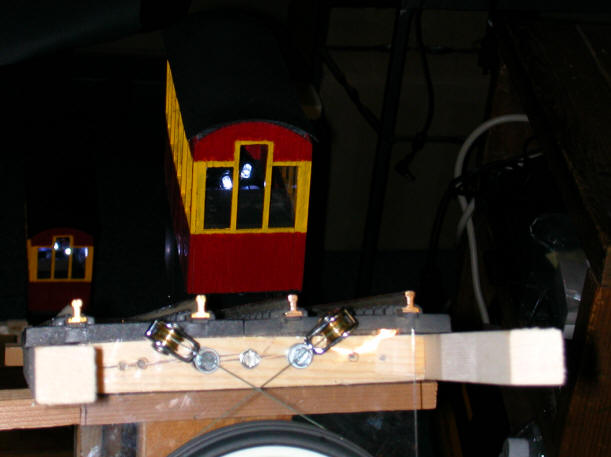
This system worked like a charm! That is not to say that there were no problems associated with the powered part of the incline. The first major problem came from my choice of braided fishing line for the incline’s cable. I thought that it would be ideal as it is available in dark colors and is pretty close to scale size. What I didn’t count on was the thin fishing line getting caught between the pulley's metal frame and the pulley itself. A switch to 1/16” nylon cord resolved this problem. The other adaptation was the path of the cord around the wheel. When it was looped under the wheel the cord tended to slip a bit. By crossing the cord across itself before looping it once around wheel nearly the entire wheel is in contact with the cord at all times.
CONTROLLER
When I ran the trolley on the front porch a few years ago I controlled it with a
simple microprocessor based device that applied power to the trolley track
through a transistor switch. The microprocessor toggled a double pole double
throw relay to reverse the trolley. A similar device would be more than
sufficient to
control the incline. I did a quick modification to a spare speedometer
unit (see:
http://www.largescaleonline.com/members/emag/article_477.html
) and developed a controller that controlled the operation of the incline and
displayed the number of times it went up and down.
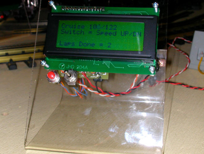
More information on the controller is on my web page at www.TrainElectronics.com
BUILDINGS
The Duquesne incline has two stations, one at the top and one at the bottom.
Since time was running out, having a little more than 24 hours before my
December 1st target date, I had to make a few compromises on the stations.
I decided to concentrate on just the station that is at the top of the incline as that is the one that would be clearly visible to all passers-by. I also decided to make this station more of a caricature of the real station rather than making it a true scale model.
My preferred material for constructing such buildings is ½” pink foam board. It is easily cut and shape with normal wood working tools and projects go together quickly. The station is made up of three sections, a tower on each side of the track and a center section that the cars pull into. The trickiest part of the structure to construct was the tapered roof on each tower. Tilting the base of my band saw to 15 degrees did the trick on that one.
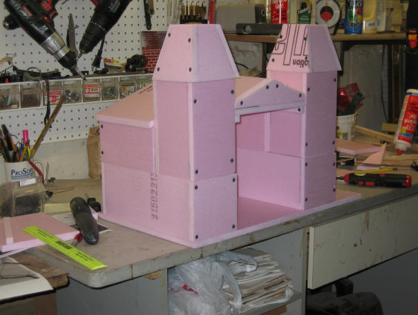
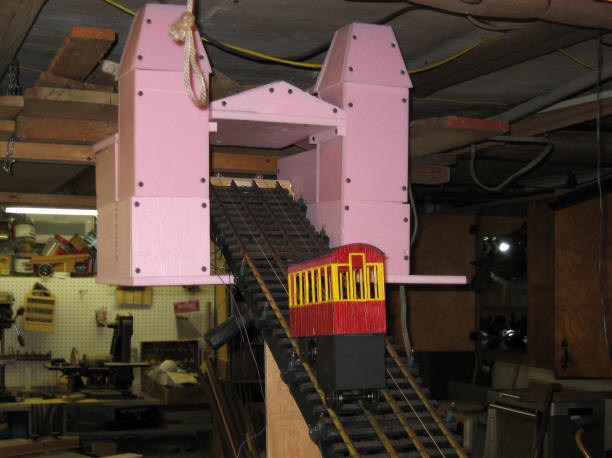
A test fitting in the garage gave me confidence that it would work in the yard.
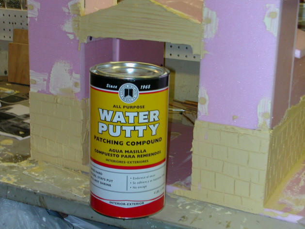
After the form of the station was complete I used a thin coat of a concrete patching material called Water Putty to add texture for the stone base and shingles on the tower roofs. I applied a thin coat of Water Putty with a putty knife and scored shingles and line for the stones when it was nearly dry. As you can see it is not a perfect match but more than adequate for my purposes.
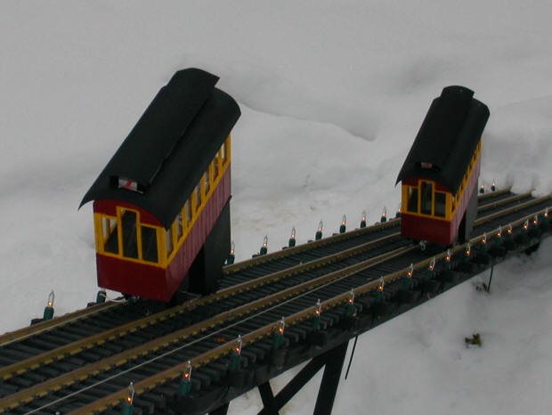
RUNNING THE INCLINE
Operation of the incline turned out to be a real pleasure. The controller is
programmed to turn on the power for about 90 seconds for each trip with a short
delay (about 30 seconds) between trips. I am pleased to report that the incline
has been running daily since December 1 without a hitch! The motor and cable
drive system has been flawless. The only problem is snow removal. We have had a
good bit of snow and freezing rain and the snow and ice needs to be removed
before the incline is put into operation each day. The average number of
trips during a 17 hour day is nearly 500!
NEW ROOF
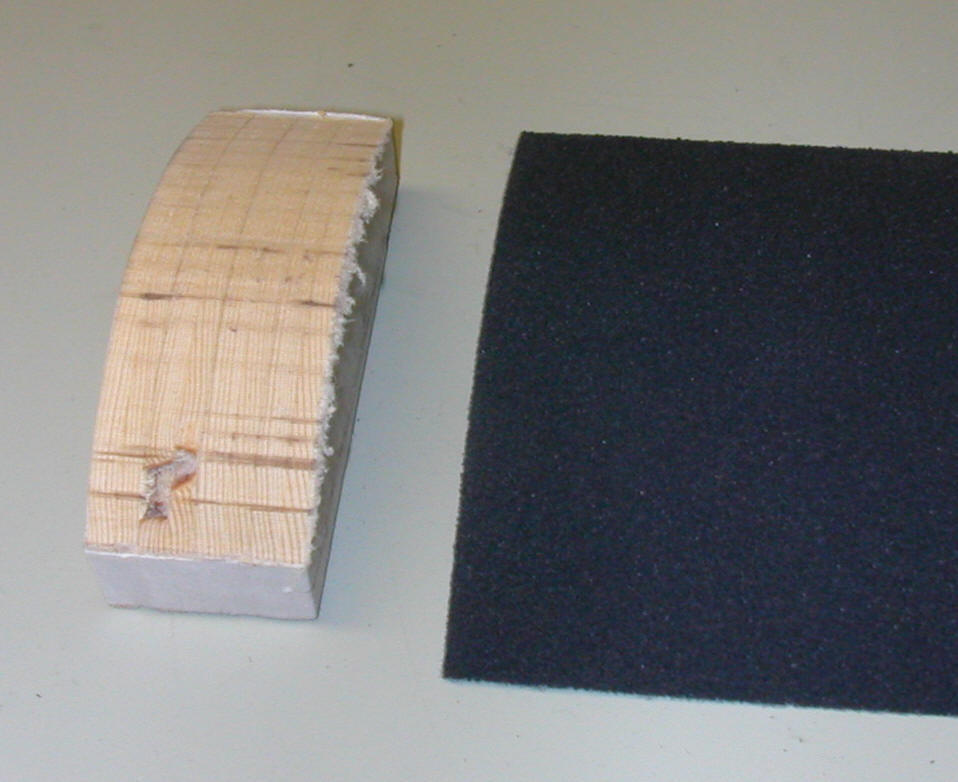
I wasn't completely satisfied with the roof on the incline and the emery paper took a beating from the rain and snow that fell the first few weeks of December. The revised, and more prototypical, roof is make of a section of 4" plastic pipe that was cut on the table saw. I heated it up with a heat gun and shaped it a bit so that it more closely met the curve on the roof trusses on the car.
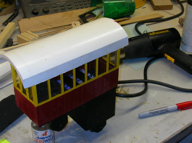
A bit of shaping on the belt sander gave a nice representation of the "hat brim" that is on the real incline's roof.
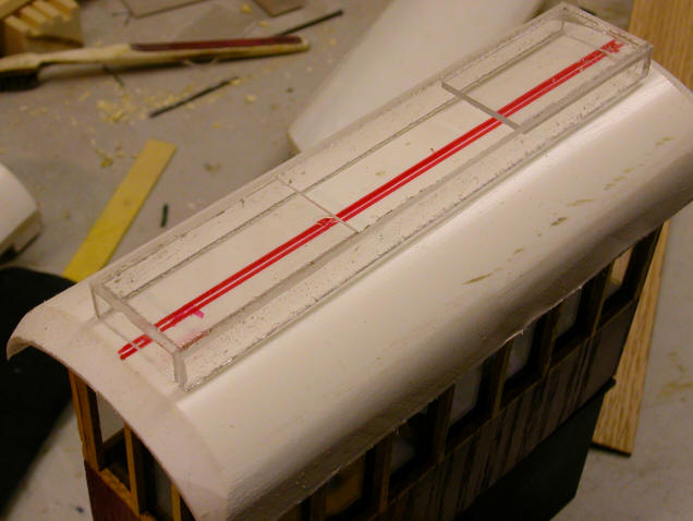
While I was at it I decided to add the raised roof section, called a clerestory, to the roof. It is made of Plexiglas so that it can be illuminated.
Here is a view of the amber LEDs that illuminate the interior of the car. Note that each LED has a current limiting resistor soldered in series with the power lead.
This photo shows the two red LEDs that illuminate the clerestory.
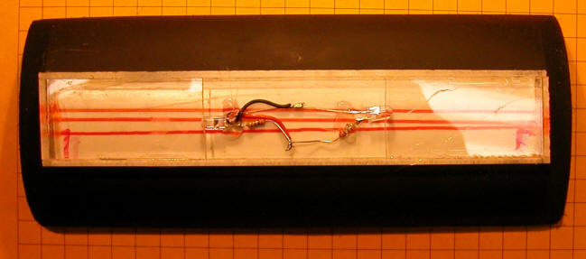
Black tape was added to make panes in the windows. Shaped pink foam was glued to the top of the clerestory to help the top roof section hold its shape. This roof was made of emery paper.

Here's the finished roof. Much better if I do say so myself! The additional lighting in the clerestory was very visible after dark and added a nice touch to the completed cars.
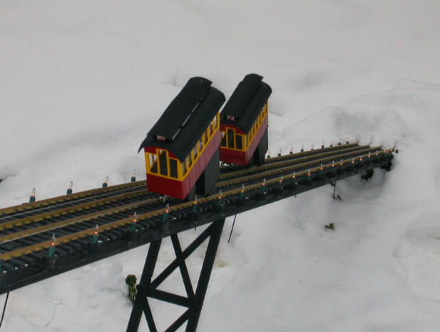
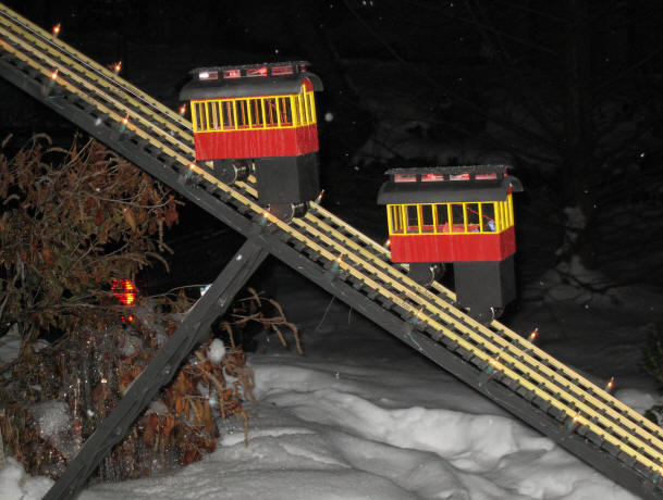
The next step may be to recreate another incline for a more permanent installation in the back yard. The Monongahela Incline, perhaps??