|
The unit shown here is the same
as those in
the article
but it uses a custom circuit board that I
designed and had fabricated.
|
| Introduction The MP3 player that I used in the Talking Defector Project is frequently used with a microcontroller like an Arduino. It can, however, be used for many applications by just adding some buttons and resistors. |
| Building the sound unit These are the parts that I used:
|
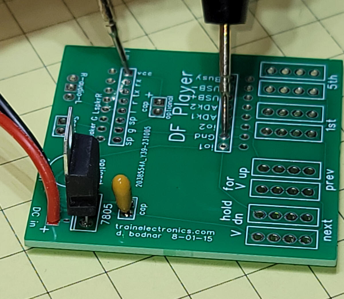
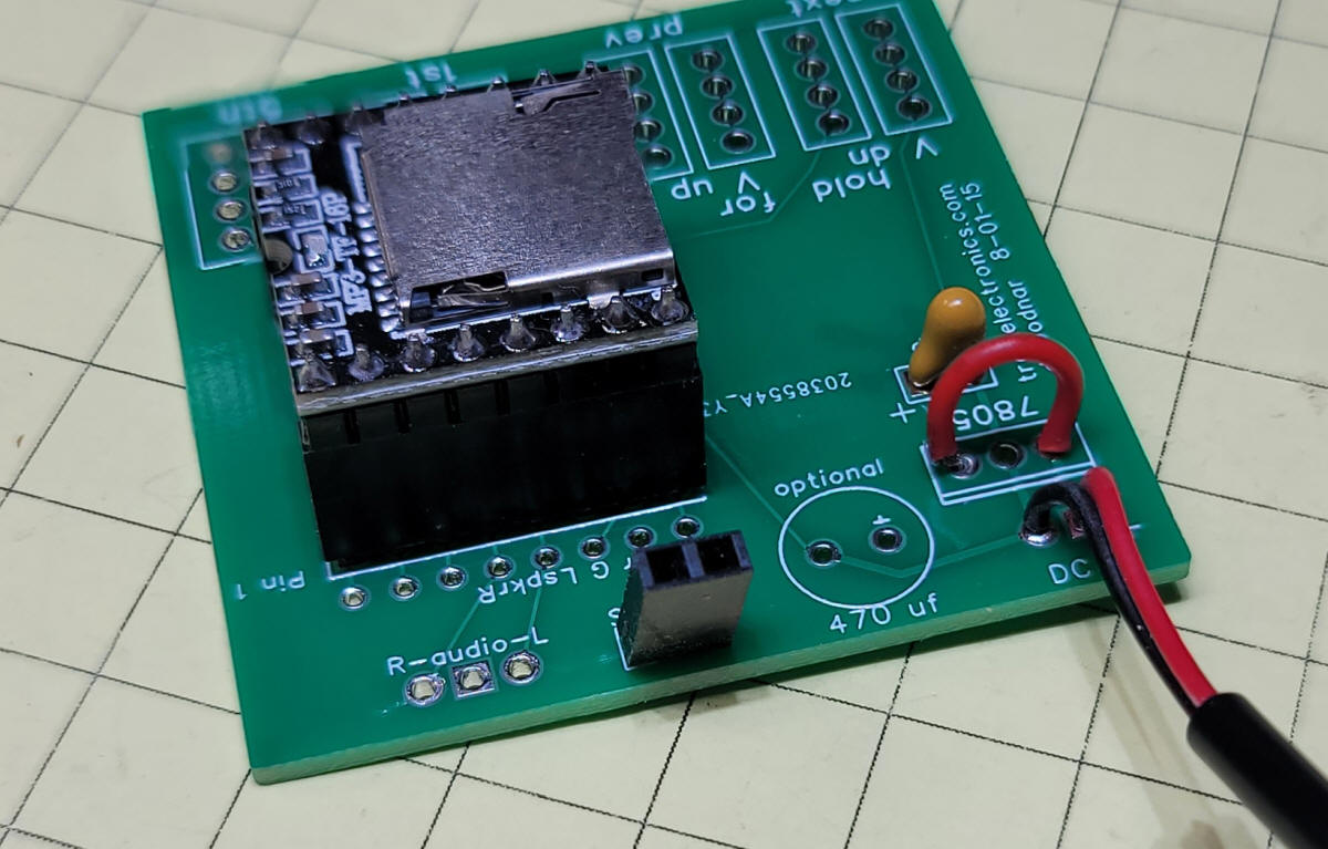
| Power Supply If you plan on supplying 8-12 volts to power the unit you need to use the 7805 voltage regulator as shown here. The tantalum capacitor needs to be inserted with the longer leg to plus and the shorter let go the negative hole. Be sure to orient the 7805 as shown in the photo below. The two meter probes are shown testing the voltage output which should be 5 volts (plus or minus a bit) - the red probe goes to "vcc" and the black to "Gnd"
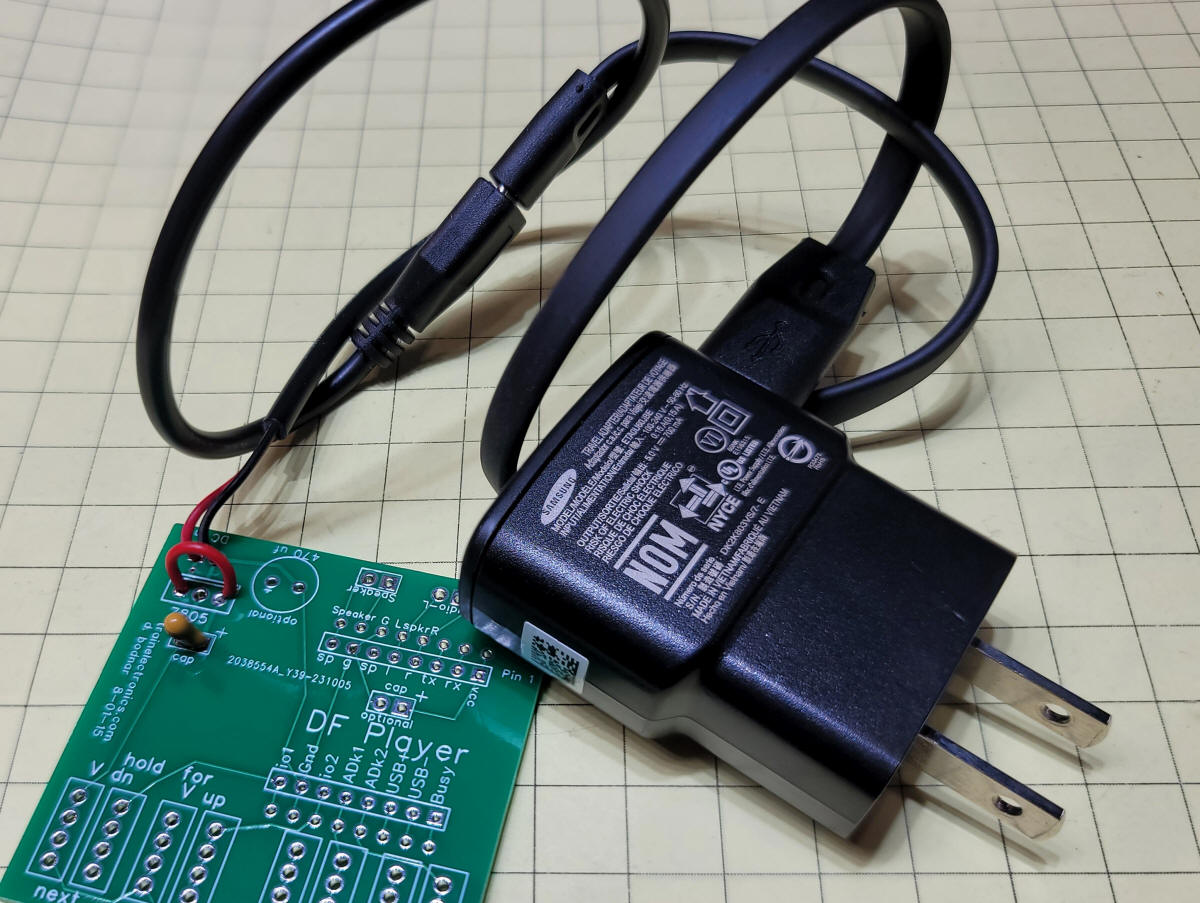
If you would prefer to run the board from 5 volts (from a 5 volt USB adapter) you can skip the 7805 and add a jumper to transfer the 5 bolts from the power input connection. I use a female micro USB adapter cable from Amazon Note that the tantalum capacitor is still used.
|
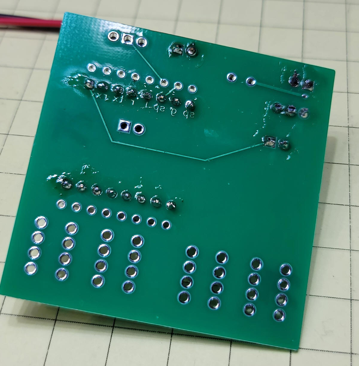
| Construction Next assemble the headers and the DFPlayer as shown. Note the orientation of the DFPlayer. Once they are aligned and inserted in the board solder being careful not to create solder bridges.
This bottom view shows what needs to be soldered. Carefully examine the board and make sure there are no solder bridges.
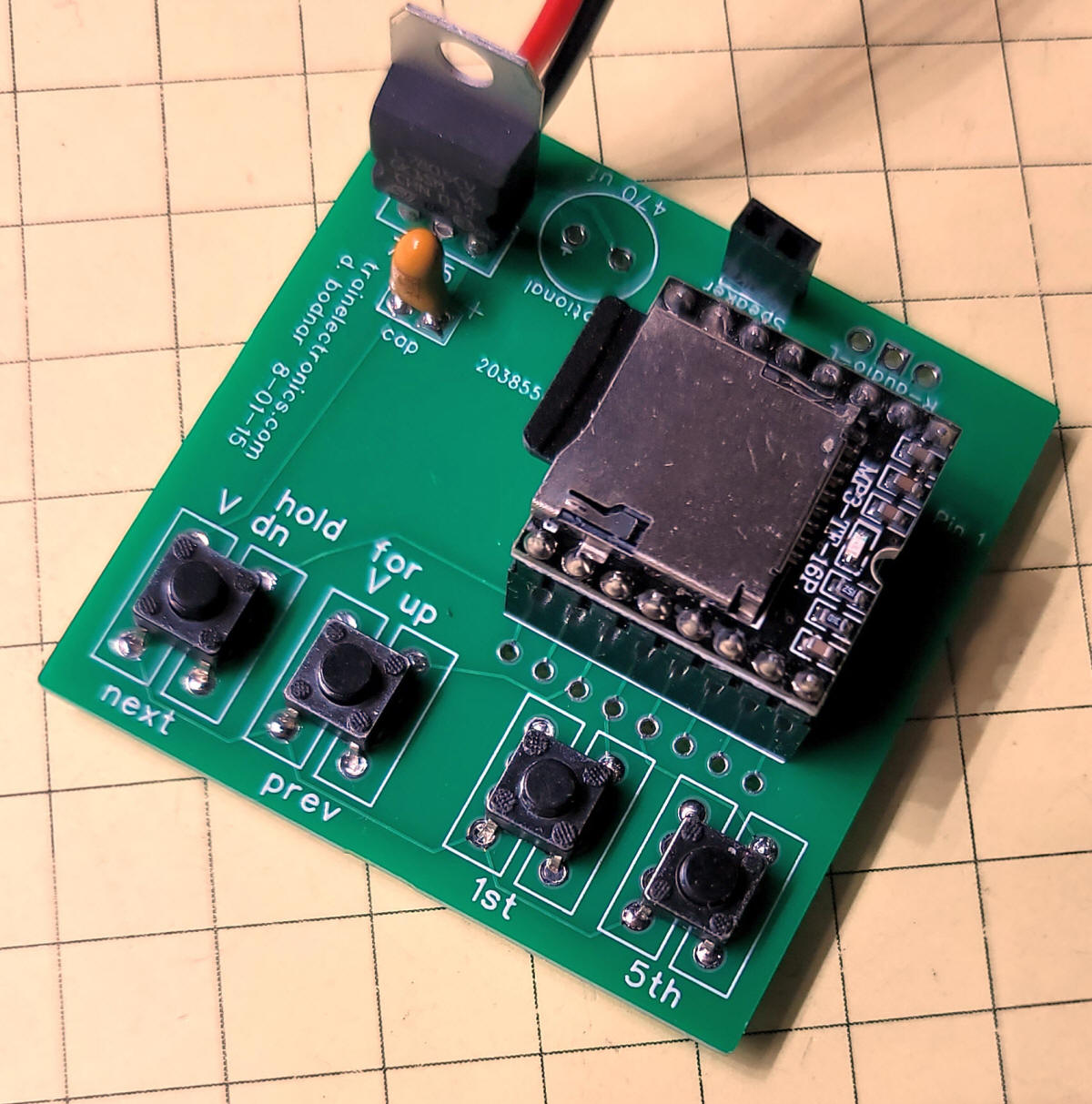
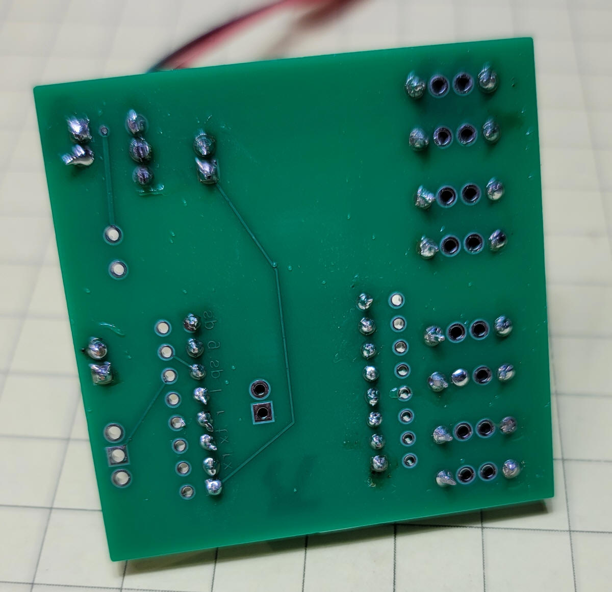
Insert the buttons being careful that the pins go through the holes.
Bottom view after buttons have been added.
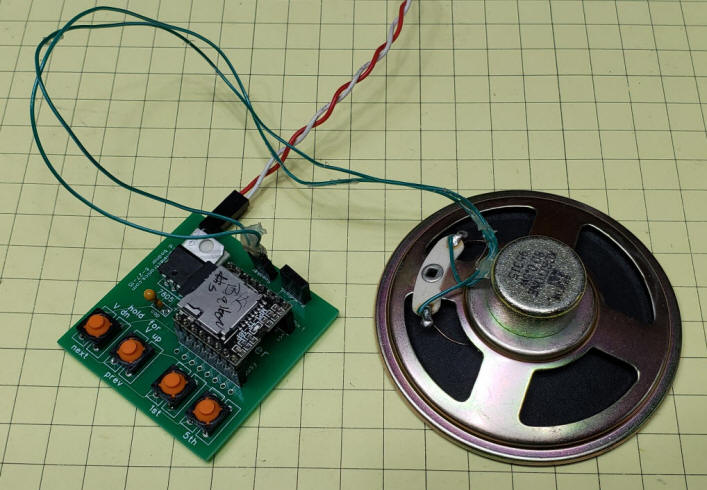
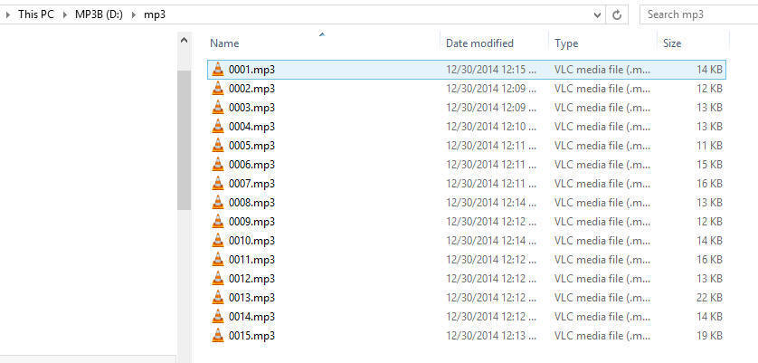
Connect an 8 ohm speaker to the socket labeled SPEAKER. If you want to have more volume than what is supplied from a single speaker you can connect a set of amplified speakers (from an old PC) to the terminals labeled R-audio-L Attach the common wire to the center terminal and the left and right channels to L & R. Insert the microSD card containing the sound file(s) - note that the mp3 files are in a directory called mp3 If only one sound is being used all you need is to name the file 0001.mp3 and put it in the mp3 directory
|
|
Recording Sounds The MP3 files were created in Audacity (see: http://audacity.sourceforge.net/ ) - some information on using Audacity is here: http://www.trainelectronics.com/MP3_project/#Audacity_-_Sound_Editor ). YouTube also has many tutorials on Audacity. |
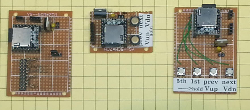
| Hand Wiring the Unit Three of the variations on this method of operation are shown here. In addition to the MP3 module each has a 7805 voltage regulator that supplies 5 volts to the player. There are also sockets with 2 and 3 pins. The 2 pin socket connects to pins 7 and 9 and can be used to drive a speaker directly. The 3 pin socket connects to ground (center pin) and to pins 4 and 5 and is used to drive an external powered speaker. The 3 pin socket is stereo while the 2 pin is mono.
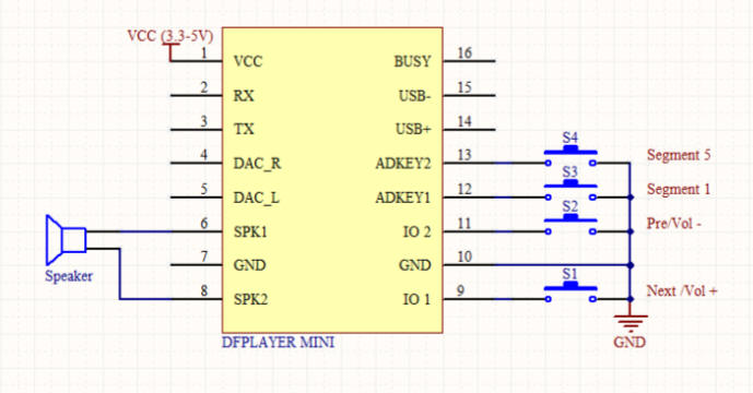
The unit on the right and the one in the center are wired as shown in this diagram. The center unit only uses buttons connected to pins 9 and 11.
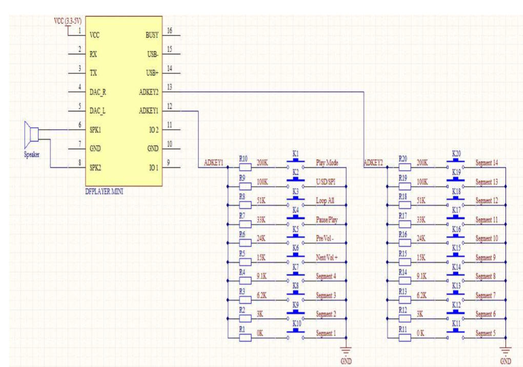
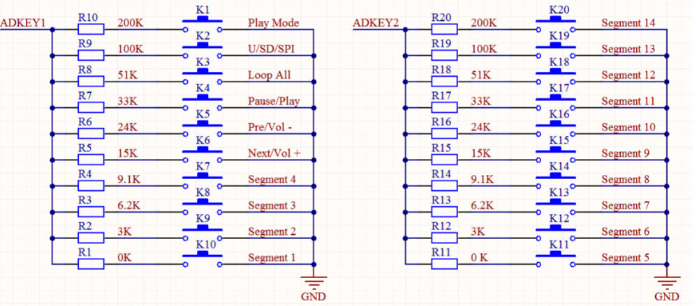
The unit on the left has 10 pairs of pins that are connected to resistors as shown in this diagram. I only wired one set of switch pins and one set of resistors and used another jumper to select if the pins go to pin 12 or 13 on the MP3 module.
This drawing may be a bit clearer.
|