Arduino DCC Controller
Revised 09-23-14 &
3-12-15 & 9-20-15 & 2-29-16
| IMPORTANT Note (2-29-16)- You may want to look over the DCC++
system before building this unit - it is much more stable and is
also much easier to build - see: NEW! DCC++ Open Source DCC Project NEW! DCC++ Infrared Throttle & Point-to-Point Controller
|
| IMPORTANT Note (3-12-2015)- the IRRemote library will not work with newer versions of the Arduino program - I had to download version 1.0.1 from http://arduino.cc/en/Main/OldSoftwareReleases to get it to work. |
| Introduction I have been experimenting with using the Arduino to receive DCC commands in order to use small dedicated DCC decoders to operate animations and other non-locomotive things on my modular layout. Thanks to a posting by Geoff Bunza on the MRH forum. In that article Geoff describes how one can build a small decoder that can be used to trigger up to 17 discrete events. I have details about my experiments with this project here: http://www.trainelectronics.com/DCC_Arduino/ The next logical step is to create a dedicated DCC controller that can be used to trigger events. I found this listing http://railstars.com/software/cmdrarduino/ and have been testing the Arduino libraries and code with great success. Please Note: The first design of a controller is shown on this web page: Arduino DCC Controller -first design |
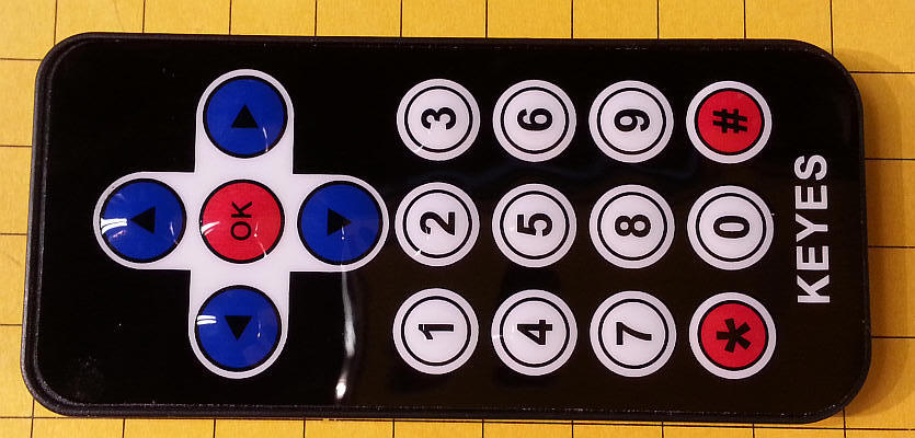
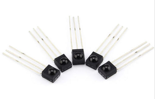
| Design Considerations The design of the user interface must be considered before gathering parts and building any device. I have used infrared TV remote controls to operate any number of PIC and PICAXE based circuits and opted to do the same with this Arduino project. There are libraries available that make using them a trivial task. The software is set up to use just a few remote keys: the numbers 0-9, the four direction buttons (up, down, left, right), an OK button and the "*" & "#" keys. The basic remote is very compact:
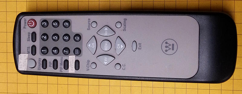
I also added codes for this Sony compatible remote. Those codes are the second code in each set as noted in the software.
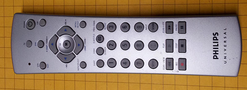
This universal remote is set for Sony codes and it works, too.
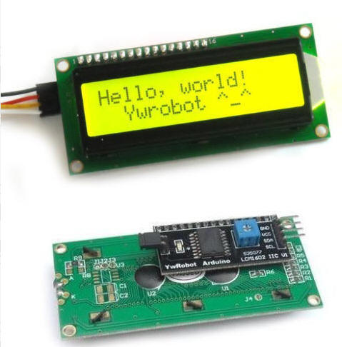
To give feedback on the controller's settings and current state of operation a two line by 16 character LCD display was added. This is a device that only has four connections, +5 volts, ground and two for the I2C interface. The up and down arrow keys accelerate or decelerate the locomotive. The "*" key stops the train and the number keys 1--9 activate auxiliary functions. The zero key ("0") resets all functions to "off". The locomotive's DCC address is set by pressing the OK button. A two digit (00-99) address can be entered. Press OK again to return to the main screen. Note that the address is retained in memory until it is reset. |
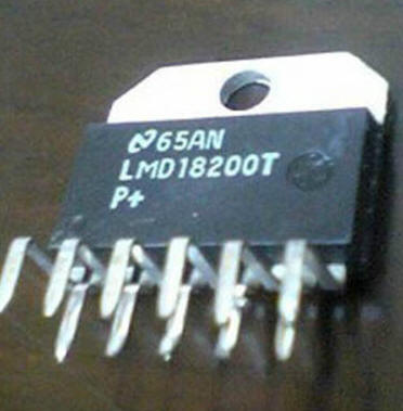
| Power Since this is designed to be a stand-alone DCC controller power needs to be added to the DCC signals created by the Arduino. This functionality is provided by the 11 pin LMD18200 H-Bridge. This device is frequently used to power DC motors as it contains the electronic equivalent of a double pole, double throw toggle switch. This, along with the ability to change speed of a motor with a PWM signal, allows speed and direction control. In this application the direction pin (pin 5) accepts the DCC signal and applies it to the track power. Note that the PWM pin (pin 5) is pulled high and that the brake pin (pin 4) is pulled low by the Arduino's pin 8. This allows you to disable power to the track by changing pin 8 from low to high.
|
|
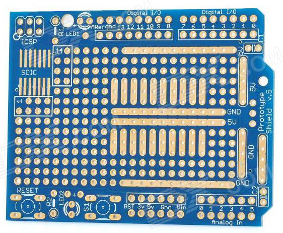
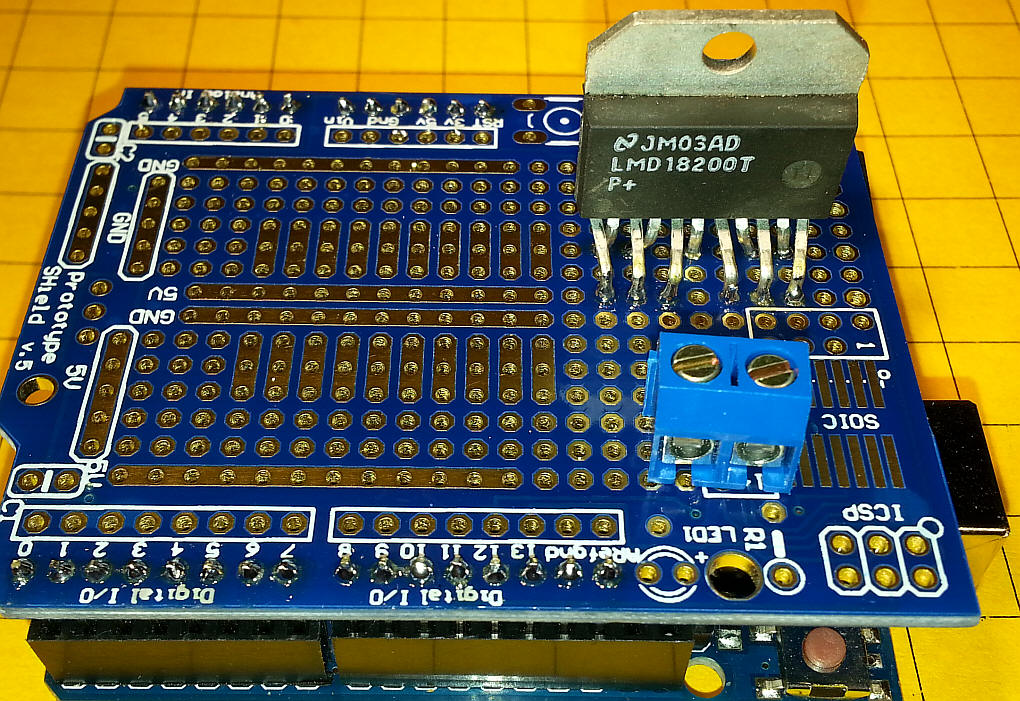
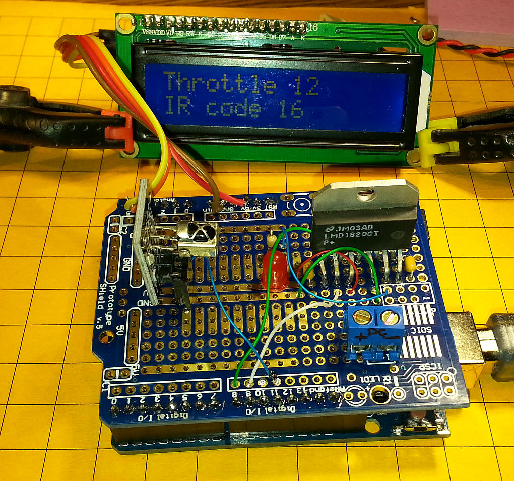
Shield Version of the Controller In keeping with the "shield" theory of building circuits for the Arduino I decided to build up a single board DCC controller circuit. The parts that were used are shown here. Arduino shield board: http://www.dx.com/p/arduino-prototyping-shield-pcb-board-blue-138294#.VBi1gBbEf5A
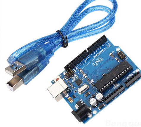
Arduino Uno - http://www.banggood.com/Wholesale-Arduino-Compatible-R3-UNO-ATmega16U2-AVR-USB-Board-p-68537.html (about $9)
LMD18200 - http://www.ebay.com/itm/390221396945?_trksid=p2059210.m2749.l2649&ssPageName=STRK%3AMEBIDX%3AIT
Heat Sink: http://www.suntekstore.com/goods-14004198-12pcs_aluminum_heat_sink_for_to220_l298n.html Two Pin Terminals: http://www.ebay.com/itm/5-x-DG301-Screw-Terminal-Block-2-Positions-5mm-FREE-SHIPPING-/250983097231?pt=LH_DefaultDomain_0&hash=item3a6fc2238f IR Receiver module: http://www.ebay.com/itm/AGH-5Pcs-IR-Receiver-Module-38kHz-TSOP4838-DIP-3-SSY-2761-/141191904377?pt=LH_DefaultDomain_0&hash=item20dfb17c79
|
|
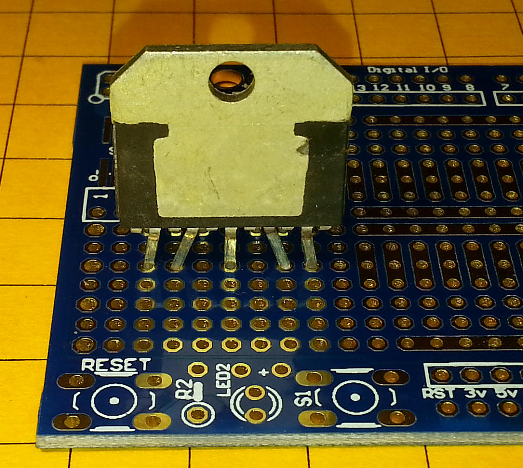
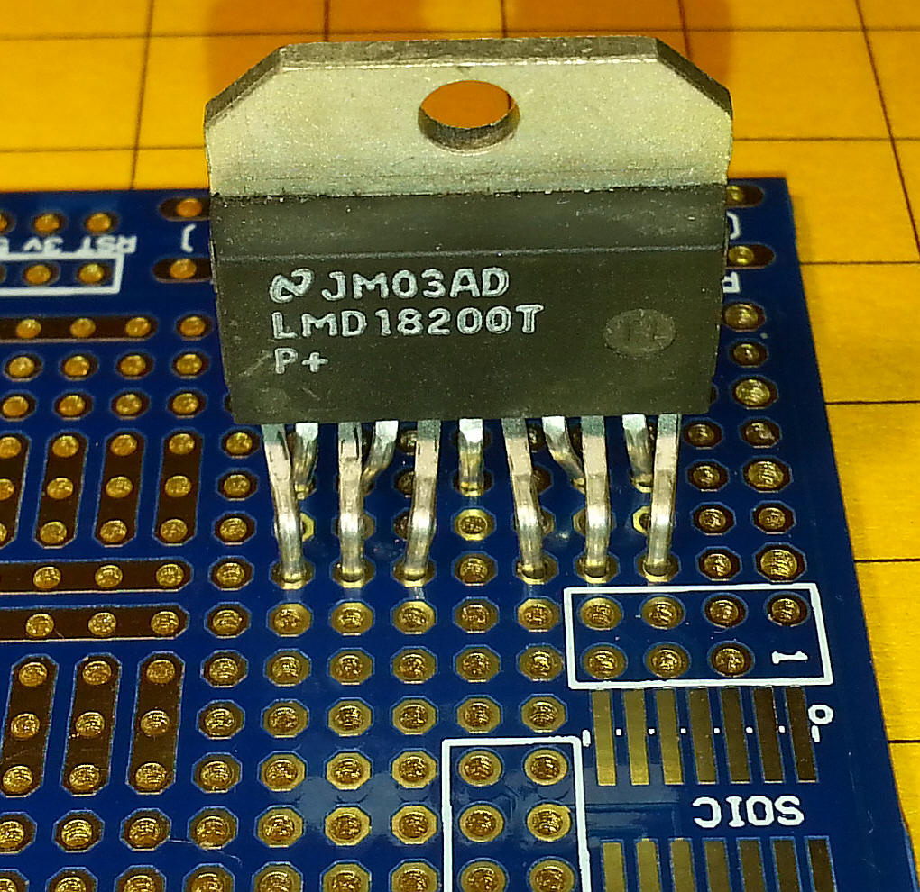
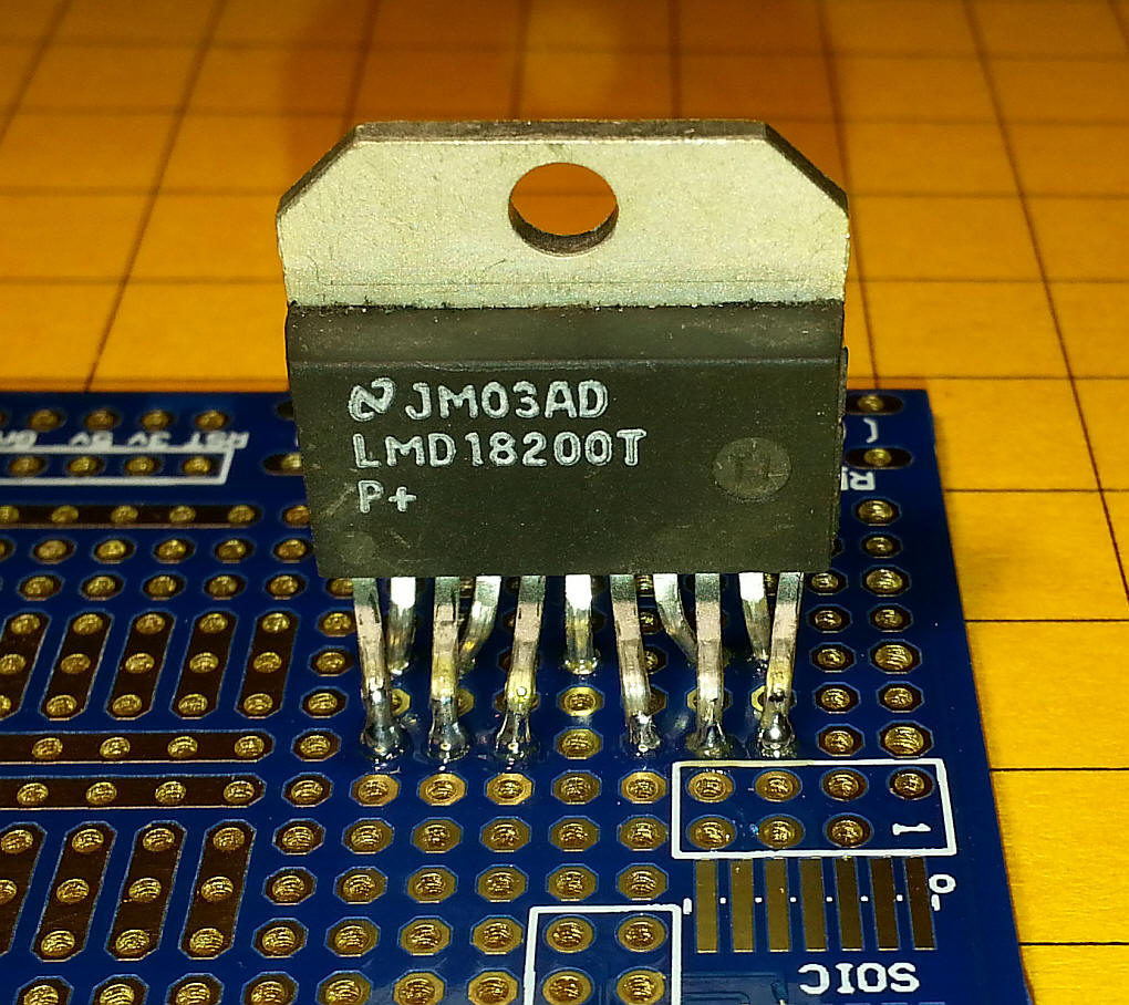
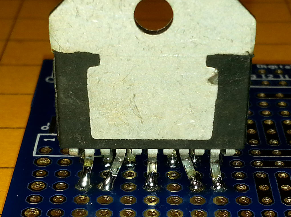
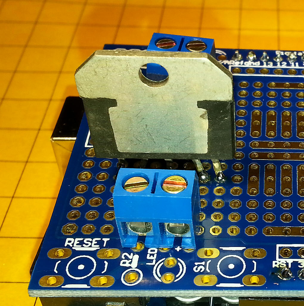
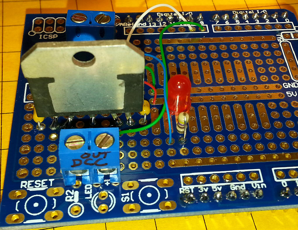
The LM18200 does not have pins that are on the
normal 0.10" centers. I found that I could bend them as shown
in the next two photos and get them to fit into the prototype board.
Note that some of these devices have thicker leads that might
require some reaming of the holes to get them to fit.
There is a row of unused holes between the front pins and the back pins.
When you solder the pins make sure that solder is on both sides of the board.
Two terminal blocks supply 12 volts DC (the block at the back of the photo) and connect DCC to the track (the block in the foreground).
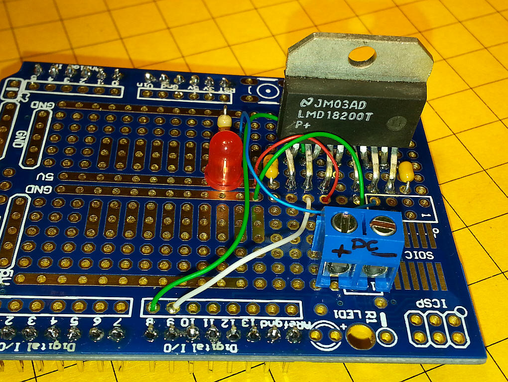
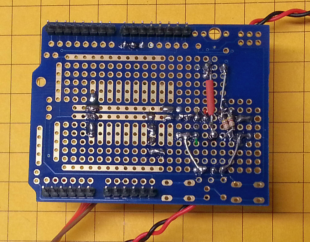
Some of the wiring is on the top of the board.
And some of the wiring is on the back. Heavier wire was used for the DC in and DCC out connections.
The red LED connects to the Thermal Warning pin on the LM18200.
The little block to the left, labeled Keyes, contains the IR detector that "sees" the IR from the TV remote. The one shown came with the Keyes remote kit. The power that goes to the DC terminals is separate from the USB power that goes to the Arduino. If you want to run the unit from one supply disconnect the USB and feed the power that goes to the DC in terminals to the power plug on the Arduino.
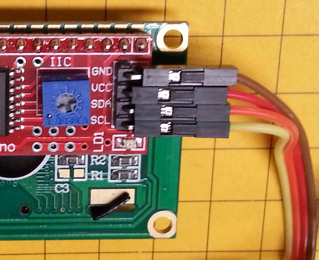
The LCD has four connections on its back. GND goes to ground, VCC to 5 volts, SDA to pin A1 and SCL to pin A0.
|
|
Schematic The schematic shows the Arduino (the four blocks of pins marked Digital, Power and Analog), the IR receiver, the LCD display and the LM18200. There are very few parts beyond a few caps and resistors. Note that the enable pin on the LM18200 (pin 4) goes to pin D8 on the Arduino. That gives you the ability to turn the H Bridge on and off from software. There is also a Current Sense output on the LM18200 but it is not currently connected. It could be hooked up to one of he Analog pins on the Arduino so that you could keep track of the power being pulled through the H Bridge. You could easily add a 3 or 4 LED bar graph to display the power level or add it to the LCD display. PLEASE NOTE: The order of the IR Receiver pins could be different from those shown in the schematic depending on which receiver you are using.
|
Arduino Code - version:
CmdrArduino_Controller_IR_LCD_v2_7/*
d. bodnar 9-23-2014
Uses 2 line LCD for display
Uses IR remote control for throttle & functions (functions not working well yet)
Uses CmdArduino library for DCC output
UP = faster - 13 - hold to repeat
DN = slower - 17 -hold to repeat
* = STOP - 11
# = Disable / enable DCC (pin 8) -12
< = - 14
> = -16
OK = Menu choices -15
*/
// the following defines the codes for Keyes brand and Sony IR remote controls
#define KeyesUp 0xFF629D
#define SonyUp 0x90
#define KeyesLeft 0xFF22DD
#define SonyLeft 0xC90
#define KeyesOK 0xFF02FD
#define SonyMenu 0x70
#define KeyesRight 0xFFC23D
#define SonyRight 0x490
#define KeyesDown 0xFFA857
#define SonyDown 0x890
#define Keyes1 0xFF6897
#define Sony1 0x10
#define Keyes2 0xFF9867
#define Sony2 0x810
#define Keyes3 0xFFB04F
#define Sony3 0x410
#define Keyes4 0xFF30CF
#define Sony4 0xC10
#define Keyes5 0xFF18E7
#define Sony5 0x210
#define Keyes6 0xFF7A85
#define Sony6 0xA10
#define Keyes7 0xFF10EF
#define Sony7 0x610
#define Keyes8 0xFF38C7
#define Sony8 0xE10
#define Keyes9 0xFF5AA5
#define Sony9 0x110
#define Keyes0 0xFF4AB5
#define Sony0 0x910
#define KeyesStar 0xFF42BD
#define SonyExit 0xC70
#define KeyesPound 0xFF52AD
#define SonyPower 0xA90
#include<EEPROM.h>
int irButton;
int LED = 13; // LED to blink when DCC packets are sent in loop
#include <IRremote.h>
int RECV_PIN = 11;
int Enable_PIN = 8; //low to enable DCC, high to stop
IRrecv irrecv(RECV_PIN);
decode_results results;
#include <DCCPacket.h>
#include <DCCPacketQueue.h>
#include <DCCPacketScheduler.h>
DCCPacketScheduler dps;
//unsigned int analog_value=0;
char speed_byte, old_speed = 0;
char temp;
byte Fx = 0;
byte DCCAddress = 3;
int irCode = 0;
int inMenu = 0; // keeps track of being in the menu area 0=out, 1=in
int digits = 0;
int upFlag = 0; // trying to get keys to repeat!
int dnFlag = 0;
#include <Wire.h>
#include <LCD.h>
#include <LiquidCrystal_I2C.h>
#define I2C_ADDR 0x27 // <<----- Add your address here. Find it from I2C Scanner
#define BACKLIGHT_PIN 3
#define En_pin 2
#define Rw_pin 1
#define Rs_pin 0
#define D4_pin 4
#define D5_pin 5
#define D6_pin 6
#define D7_pin 7
byte fn0to4 = 0; // DCC function variables
byte fn5to8 = 0;
byte fn9to12 = 0;
LiquidCrystal_I2C lcd(I2C_ADDR,En_pin,Rw_pin,Rs_pin,D4_pin,D5_pin,D6_pin,D7_pin);
unsigned long previousMillis = 0; // last time update
long interval = 2000; // interval at which to do refresh (milliseconds)
void setup() {
pinMode(LED, OUTPUT);
DCCAddress = EEPROM.read(0);
if(DCCAddress >=100){ // set defalut as 3 if not in proper range (0-99)
DCCAddress = 3;
}
pinMode(Enable_PIN, OUTPUT);
lcd.begin (16,2); // LCD is 16 characters x 2 lines
lcd.setBacklightPin(BACKLIGHT_PIN,POSITIVE);
lcd.setBacklight(HIGH); // Switch on the backlight
lcd.home (); // go home
Serial.begin(115200);
lcd.setCursor(0,0);
lcd.print("Version 2.7 ");
lcd.setCursor(0,1);
lcd.print("9-23-2014 ");
delay(1500);
lcd.clear();
irrecv.enableIRIn(); // Start the receiver
dps.setup();
dps.setFunctions0to4(DCCAddress,DCC_SHORT_ADDRESS, B00000000); //clear functions
dps.setFunctions5to8(DCCAddress,DCC_SHORT_ADDRESS, B00000000);
}
void loop() {
//this section sends DCC updates every 2 seconds (interval)
// not sure if it is necessary but the functions are slow to respond
// at times - may be due to the DCC library setting priorities as the
// speed controls always work
unsigned long currentMillis = millis();
if(currentMillis - previousMillis > interval) {
previousMillis = currentMillis;
dps.setSpeed128(DCCAddress,DCC_SHORT_ADDRESS,speed_byte);
dps.setFunctions0to4(DCCAddress,DCC_SHORT_ADDRESS, fn0to4); //clear all functions
dps.setFunctions5to8(DCCAddress,DCC_SHORT_ADDRESS, fn5to8);
digitalWrite(LED, !digitalRead(LED));
}
digitalWrite(Enable_PIN, LOW);// HIGH = disable DCC
lcd.setCursor(0,0);
lcd.print("Speed=");
lcd.print(speed_byte, DEC);
lcd.print(" ");
lcd.setCursor(11,0);
lcd.print("ad=");
if(DCCAddress <=9){
lcd.print("0"); // add leading zero for single digit addresses
}
lcd.print(DCCAddress, DEC);
lcd.setCursor (14,1); // go to end of 2nd line
// lcd.print("IR code ");
lcd.print(irButton, DEC);
lcd.print(" ");
lcd.setCursor(5,1);// start of 2nd line
// pad with leading zeros
String temp = "0000" + String(fn0to4,BIN);
int tlen= temp.length() - 5;
lcd.print(temp.substring(tlen));
temp = "000" + String(fn5to8,BIN);
tlen= temp.length() - 4;
lcd.setCursor(0,1);// start of 2nd line
lcd.print(temp.substring(tlen));
if (irrecv.decode(&results))
{
translateIR();
Serial.println(irButton,DEC);
irrecv.resume(); // Receive the next value
}
byte button_state = digitalRead(4); //high == not pushed; low == pushed
if ((irButton >0 && irButton <13) | (irButton ==14 | irButton == 16)){
upFlag=0;
dnFlag=0; ////MAY NEED TO PUT THIS ON EACH KEY
}
if(irButton >=1 && irButton <=10){ //Funtions done with numbers 1-9 - clear all with 10
doFunction();
irButton=0;
}
// MENU SECTION - stays here to get DCC address
if (irButton==15 ) //OK key for menu choices
{
Serial.println("found OK (menu)");
inMenu=1;
lcd.clear(); // blank screen
lcd.setCursor(0,0);
lcd.print("MENU");
lcd.setCursor(0,1);
lcd.print("Ent 2 digit add");
for (int i =0; i = 1; i++){ // do twice
if (irrecv.decode(&results))
{
translateIR();
irrecv.resume(); // Receive the next value
}
if (irButton == 15 && inMenu == 0){
Serial.print("BREAK OUT ");
Serial.println(inMenu, DEC);
inMenu=0;
irButton=0;
digits=0;
lcd.clear();
break;
}
if (irButton >=1 && irButton <=10)
{
if (digits==1){
DCCAddress = DCCAddress * 10;
Serial.print("x10 address ");
Serial.println(DCCAddress, DEC);
if(irButton != 10){ // only add it not zero (zero button or remote returns a 10)
DCCAddress = DCCAddress + irButton;
}
lcd.setCursor(0,1);
if(DCCAddress <=9){
lcd.print("0"); // add leading zero for single digit addresses
}
lcd.print(DCCAddress, DEC);
lcd.setCursor(0,0);
lcd.print("OK to Exit Menu:");
digits = 3;
inMenu=0;
EEPROM.write(0,DCCAddress);
}
if (digits ==0){
DCCAddress = irButton;
if (DCCAddress==10){
DCCAddress = 0; // "0" button returns 10 so make it zero
}
Serial.print("dig 1 address ");
Serial.println(DCCAddress, DEC);
lcd.clear(); // blank screen
lcd.setCursor(0,0);
lcd.print("New Address");
lcd.setCursor(0,1);
lcd.print(DCCAddress, DEC);
digits = 1;
delay(500);
irButton=0;
}
Serial.print("new address ");
Serial.println(DCCAddress, DEC);
}
irButton=0;
}
irButton=0;
}
//END MENU SECTION
if (irButton==13 | (irButton==99 && upFlag==1)) // repeat key (99)
{
Serial.println("found UP");
speed_byte++;
upFlag=1;
dnFlag=0;
irButton=0;
}
if (irButton==16)
{
Serial.println("found UP ");
speed_byte++;
irButton=0;
}
if (irButton ==17 | (irButton==99 && dnFlag==1))
{
Serial.println("found DN");
speed_byte--;
dnFlag=1;
upFlag = 0;
irButton=0;
}
if (irButton ==14)
{
Serial.println("found DN ");
speed_byte--;
irButton=0;
}
if (irButton==11) //* key - does STOP
{
Serial.println("found ***");
speed_byte=0;
irButton=0;
}
//Functions will not work without this to limit speed command to only new speeds
if(speed_byte != old_speed)
{
speed_byte = constrain(speed_byte, -127, 127);
dps.setSpeed128(DCCAddress,DCC_SHORT_ADDRESS,speed_byte);
old_speed = speed_byte;
}
dps.update();
} //END LOOP
int translateIR() // takes action based on IR code received
// describing KEYES Remote IR codes (first) and Sony IR codes (second)
{
Serial.println(results.value, HEX);
switch(results.value)
{
case KeyesUp: //Keyes remote code for UP
case SonyUp: //Sony remote code for UP
Serial.println(" UP");
irButton = 13;
break;
case KeyesLeft:
case SonyLeft:
Serial.println(" LEFT");
irButton = 14;
break;
case KeyesOK:
case SonyMenu:
Serial.println(" -MENU-");
irButton = 15;
break;
case KeyesRight:
case SonyRight:
Serial.println(" RIGHT");
irButton = 16;
break;
case KeyesDown:
case SonyDown:
Serial.println(" DOWN");
irButton = 17;
break;
case Keyes1:
case Sony1:
Serial.println(" 1");
irButton = 1;
break;
case Keyes2:
case Sony2:
Serial.println(" 2");
irButton = 2;
break;
case Keyes3:
case Sony3:
Serial.println(" 3");
irButton = 3;
break;
case Keyes4:
case Sony4:
Serial.println(" 4");
irButton = 4;
break;
case Keyes5:
case Sony5:
Serial.println(" 5");
irButton = 5;
break;
case Keyes6:
case Sony6:
Serial.println(" 6");
irButton = 6;
break;
case Keyes7:
case Sony7:
Serial.println(" 7");
irButton = 7;
break;
case Keyes8:
case Sony8:
Serial.println(" 8");
irButton = 8;
break;
case Keyes9:
case Sony9:
Serial.println(" 9");
irButton = 9;
break;
case Keyes0:
case Sony0:
Serial.println(" 0");
irButton = 10;
break;
case KeyesStar:
Serial.println(" *");
irButton = 11;
break;
case SonyExit: //EXIT
Serial.println(" *");
irButton = 11;
break;
case KeyesPound:
Serial.println(" #");
irButton = 12;
break;
case SonyPower: //POWER
Serial.println(" #");
irButton = 12;
break;
case 0xFFFFFFFF:
Serial.println(" REPEAT");
irButton = 99;
break;
default:
Serial.println(" other button ");
irButton = 99;
}// End Case
delay(100); // Do not get immediate repeat
} //END translateIR
//START DO FUNCTION BUTTONS
int doFunction(){
int irTemp= irButton-1;
lcd.setCursor (14,1); // go to end of 2nd line
/// lcd.print("FN code ");
lcd.print(irButton, DEC);
Serial.print("got a keypad button ");
Serial.println(irButton,DEC);
if (irTemp<=4){
if(bitRead(fn0to4,irTemp)== 0 ){
bitWrite(fn0to4,irTemp,1);
}
else {
if(bitRead(fn0to4,irTemp)== 1 ){
bitWrite(fn0to4,irTemp,0);
}
}
dps.setFunctions0to4(DCCAddress,DCC_SHORT_ADDRESS,fn0to4);
Serial.print(fn0to4,BIN);
Serial.println(" fn0to4");
}
if (irTemp>=5 && irTemp<=8){
irTemp=irTemp-5;
if(bitRead(fn5to8,irTemp)== 0 ){
bitWrite(fn5to8,irTemp,1);
}
else {
if(bitRead(fn5to8,irTemp)== 1 ){
bitWrite(fn5to8,irTemp,0);
}
}
dps.setFunctions5to8(DCCAddress,DCC_SHORT_ADDRESS,fn5to8);
Serial.print(fn5to8,BIN);
Serial.println(" fn5to8");
}
if (irButton == 10)
{
lcd.setCursor (14,1); // go to end of 2nd line
/// lcd.print("FN code ");
lcd.print(irButton, DEC);
Serial.println("got a keypad button 0 (reads as 10)");
dps.setFunctions0to4(DCCAddress,DCC_SHORT_ADDRESS, B00000000);
dps.setFunctions5to8(DCCAddress,DCC_SHORT_ADDRESS, B00000000);
irButton = 0;
fn0to4 = B00000000; //clear variables for which functions are set
fn5to8 = B00000000;
delay(500);
irButton=0;
}
irButton = 0;
delay(500);
}
//END DO FUNCTION BUTTONS
|