| There are two different circuit boards that are used to give
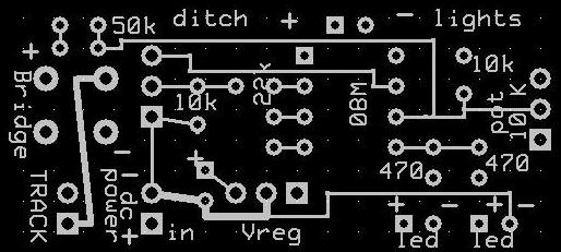
different options with the ditch lights. Each board &
schematic is shown below along with programming and connection
options specific to it.
|
|
This version of the board can be used in several ways:
|
|
The version of the board shown below can also be used in
several ways:
|
|
 |
|
 |
|
The video below shows the ditch lights circuit on a smaller, surface mount, circuit board. The board is based on a board used on the Bike Blinker Plus. Right
click the box below and select PLAY |
|
|
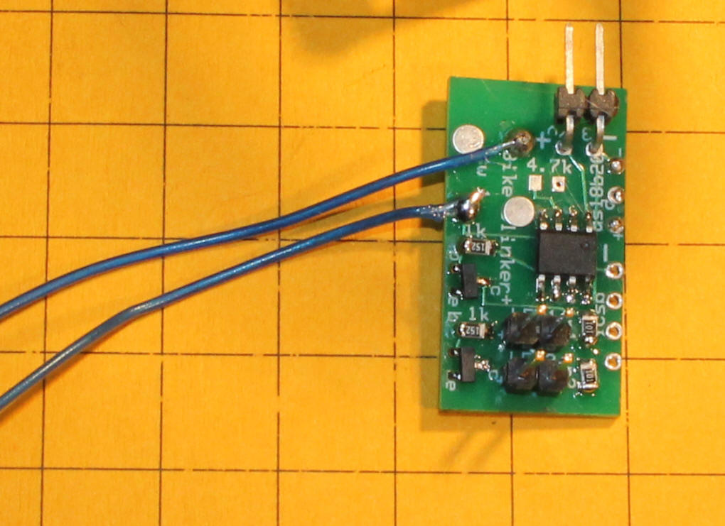
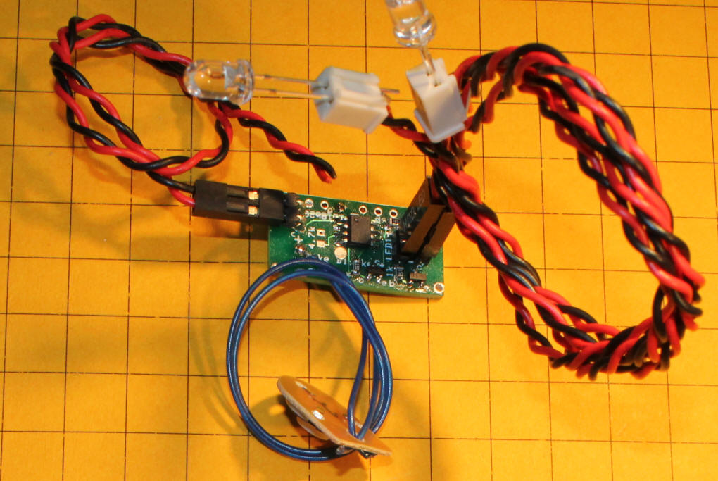
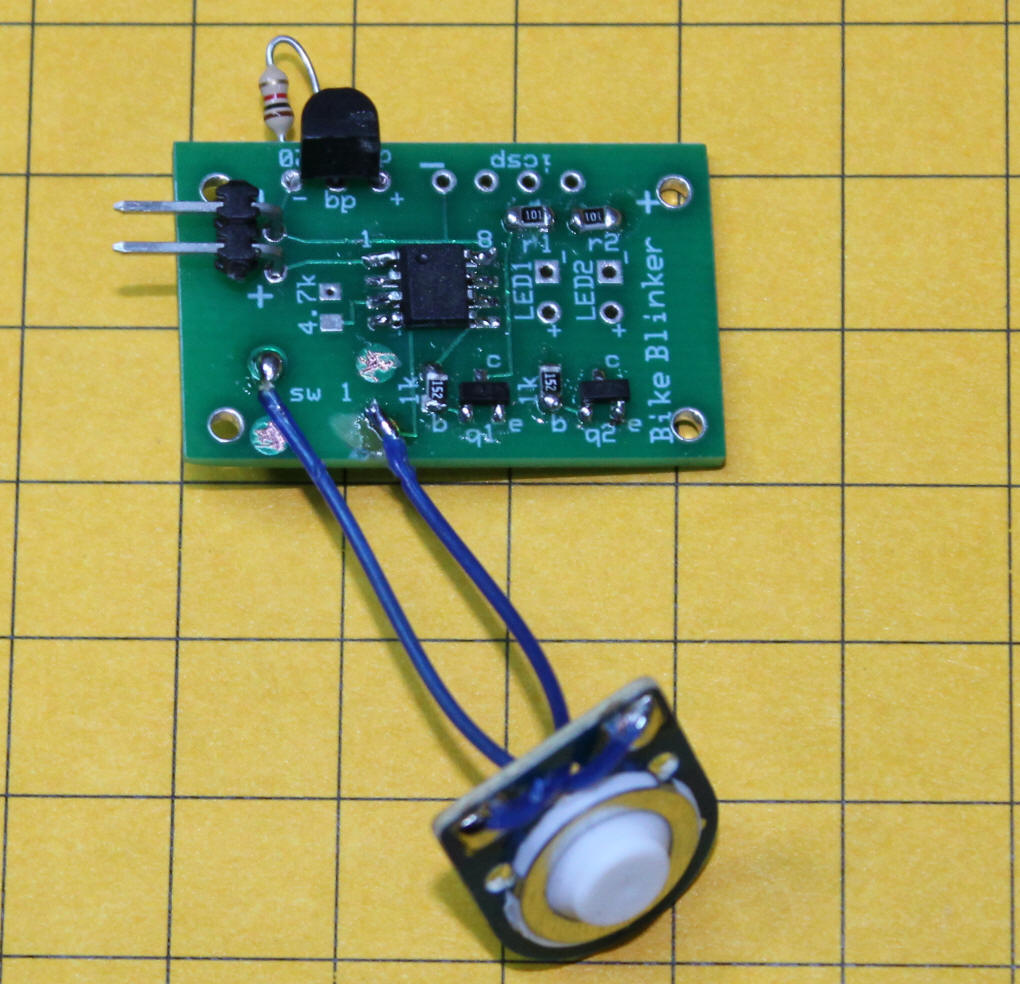
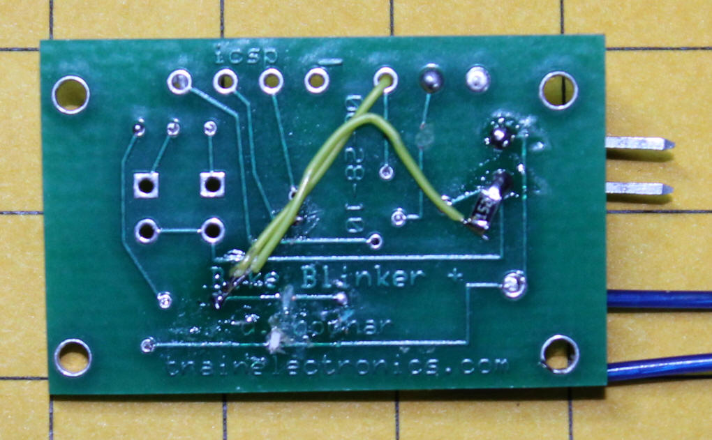
The blue wires go to a normally open switch.
When the switch is open the two LEDs are on and do not flash. When
the switch is closed the lights go into ditch light mode flashing about
once per second.
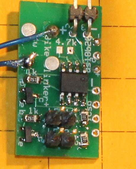
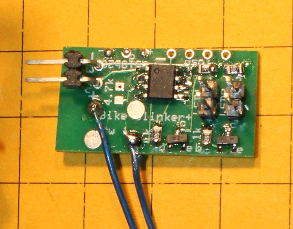
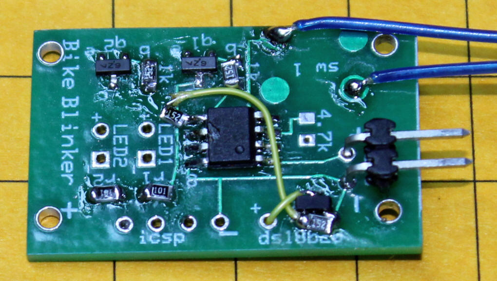
The power pins are on the left. The pin by the edge is negative and one marked "+" is positive. The LEDs connect via the pins on the right. The pins can be shortened if needed.
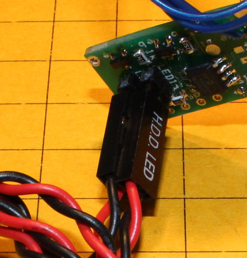
This board has the power plug inserted. The red wire is positive and the black is negative. Proper polarity MUST be observed and no more than 5 volts can be used or the unit will be damaged.
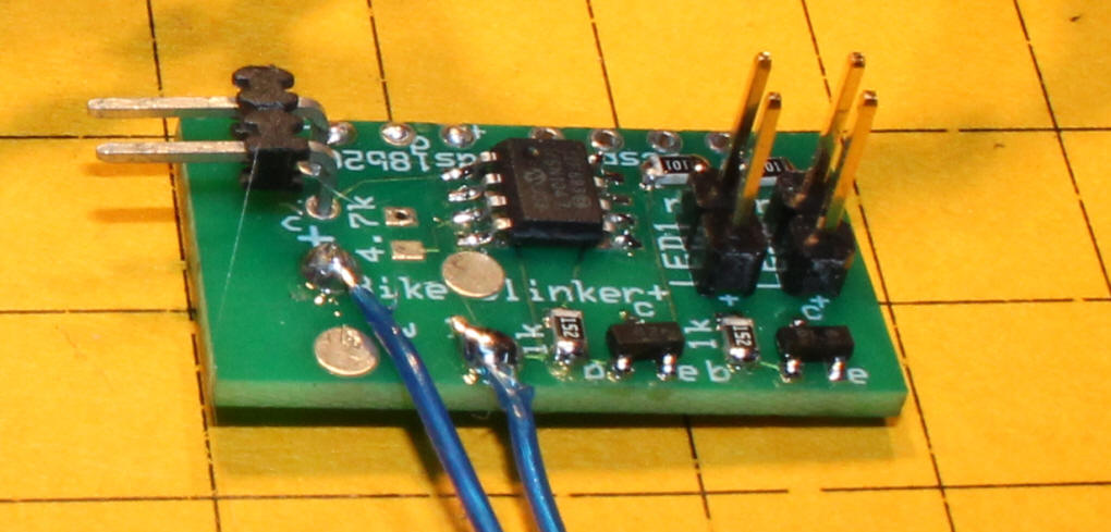
This close-up shows that the polarity on the LED connections is reversed on the two sets of pins. On the outer set of pins the positive is towards the top and on the inner set the positive is towards the bottom.
Two 100 ohm surface mount resistors have been installed on the board in the lower right corner. If the LEDs are too dim these resistors can be replaced by smaller value resistors or jumpered completely.
In the bottom right are two Mosfets - the one on the left (marked with a "z") is a n-channel and the one on the right (marked "L") is a p-channel
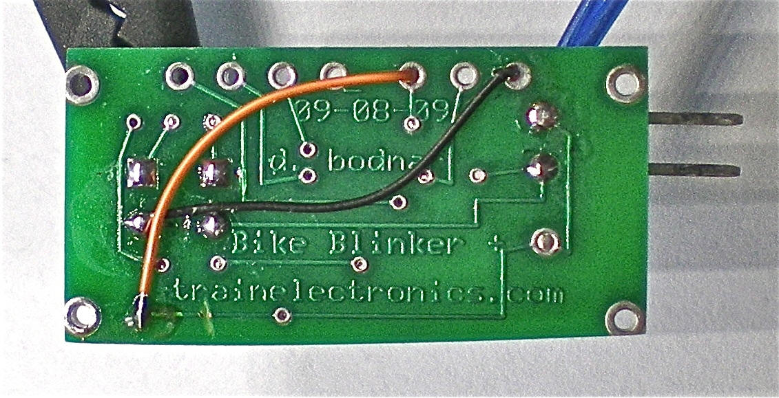
The wiring on the back of the board has been modified to accommodate the ditch light function. Two traces have been cut (under "tra" in trainelectronics.com. and to the left a few mm from the "B" in Bike Blinker. The orange wire supplies + voltage and the black ground.
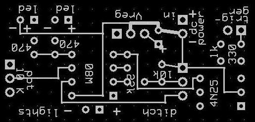
The revised schematic for this version is below.
|
|
| Common Anode Modification The modification shown here allows you to power common anode LEDs from one output on the microcontroller. It is based on a circuit that was developed to power incandescent bulbs. Note that the schematic shows back-to-back LEDs at the far right, incandescent bulbs and common anode LEDs (D2 and D4) in the lower left - although all three sets of lights could be used at the same time only one is likely to be installed at any one time.
In the next two photos the modification was done with through-hole components, a 2N2222 and several 1k / 1/8 watt resistors. No traces were cut on the top of the board. The transistor was installed into holes from an unused component.
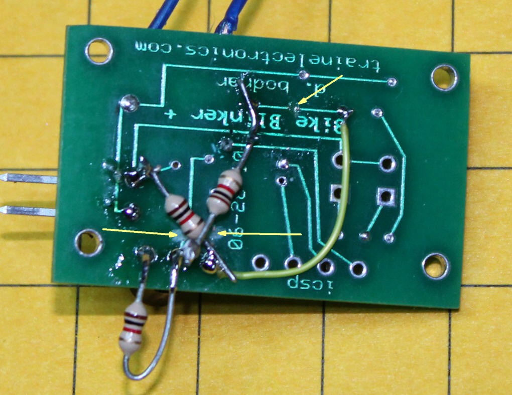
Changes were made to the back of the board. Three 1K resistors are shown. Several traces have been cut - they are marked with arrows.
Two 1500 ohm (1K will do) were installed. One is on pin 5 of the 12F683 and one goes between the base and emitter of the 2N2222 in the lower right
The yellow wire from the collector of the 2N2222 goes through a hole and connects to the point shown here. Another 1500 ohm resistor goes to +5.
|
|