PICAXE Speed Controller
AC Trolley Modification
d. bodnar
revised 01-12-12
|
Introduction There are a few problems with this mode that include:
1. When the trolley is at either end of the
point-to-point power is completely removed and any lights that may have been on
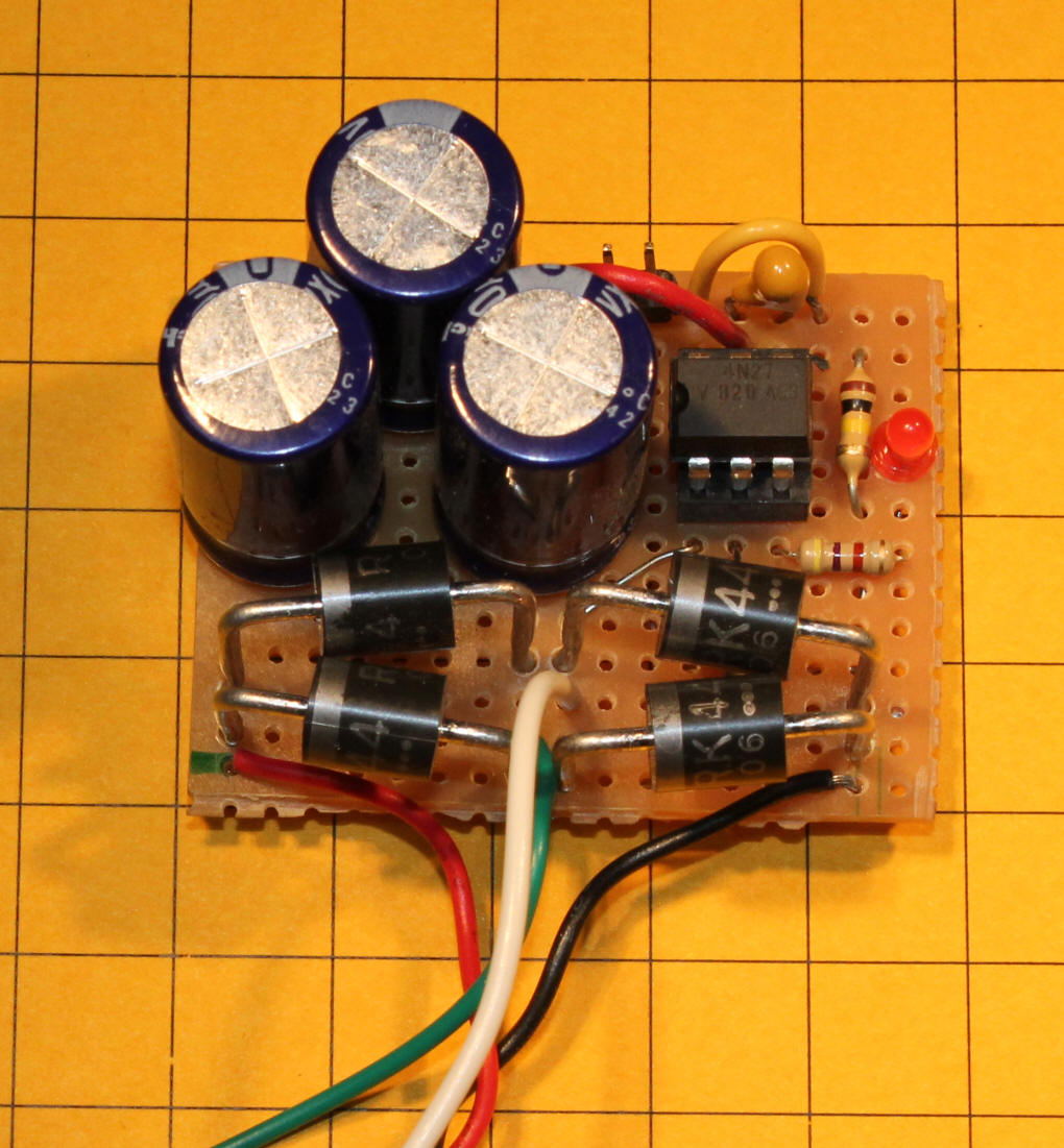
are extinguished These shortcomings can be overcome by placing the controller inside of the trolley and applying fairly high voltage AC power to the track. In order to use the controller in this manner the circuit needs to be modified. The modification is composed of a bridge rectifier, filter capacitor and a device to detect when the trolley enters one of the ends of the track. The bridge rectifier should be able to handle the maximum current that your trolley will draw, up to 3 amps. The capacitor, C2, is shown as a 2000 mfd electrolytic. Any value from about 1000 mfd and up rated at no less than 25 volts should work. I like to use capacitors that are rated at double the operating voltage so I wired three 680 mfd / 50 volt caps in parallel giving me about 2000 mfd @ 50 volts. The photo below shows the 3 capacitors and a bridge rectifier that I made up from 4 discrete diodes, a good alternative if you don't have a bridge rectifier on hand. This small circuit board also has the optoisolator and related components on it as I used this as a test unit before I installed the optoisolator on the circuit board as shown below.
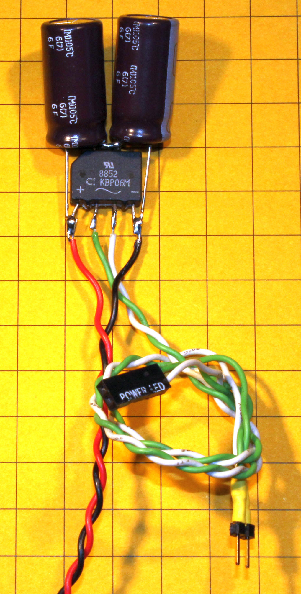
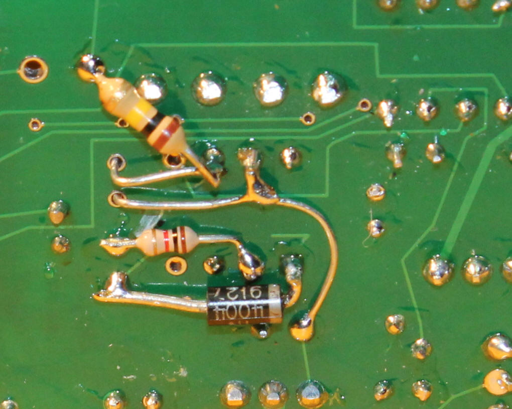
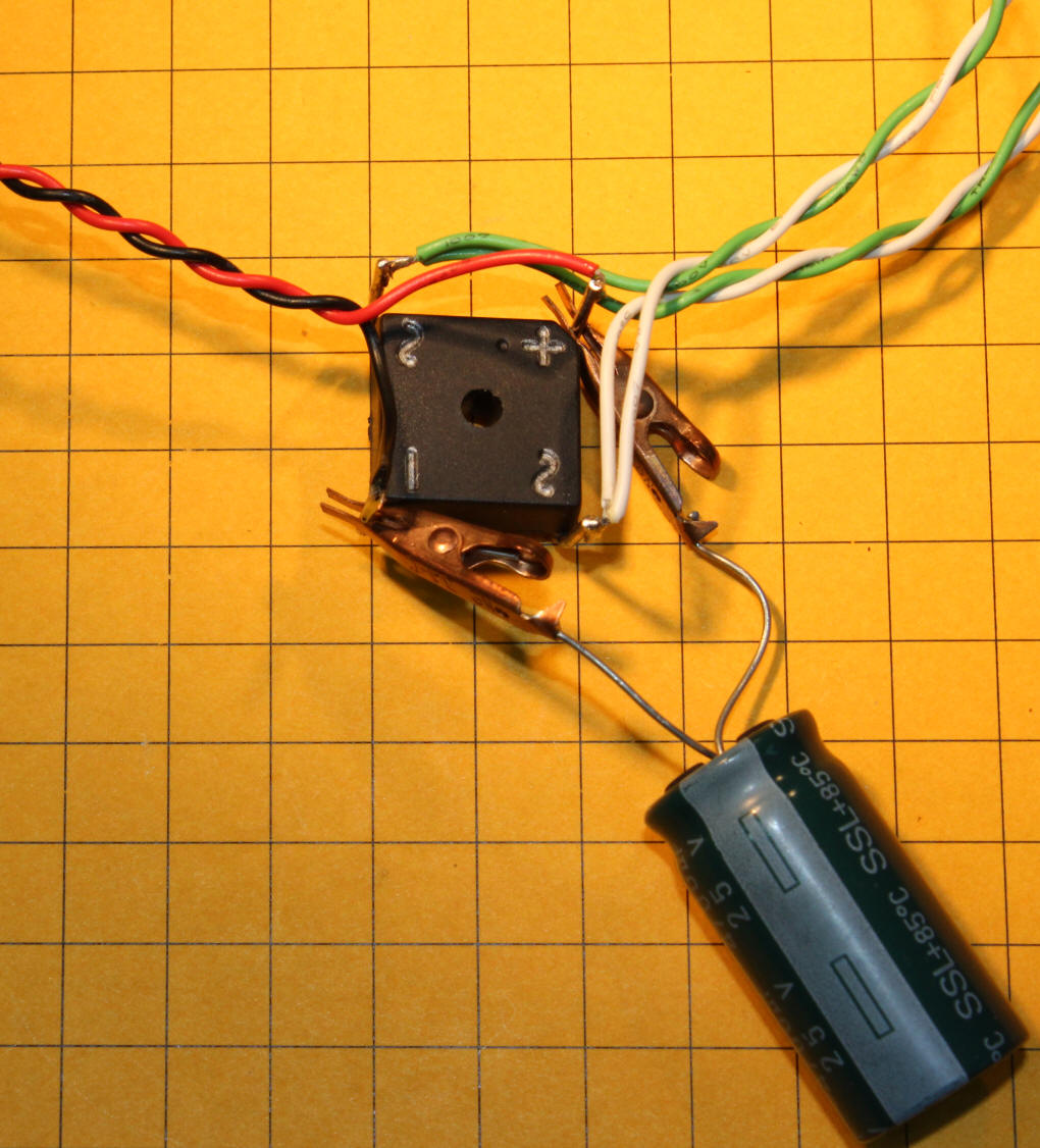
This photo shows a different style bridge rectifier and two capacitors on top of it. The two caps are 2200 uF 16 volt units. They are wired in series giving about 1000 uF at 32 volts. The green/white wires go to the track power pickups and to the bridge rectifier as well as to the input pins for the optoisolator circuit. The red/black wires deliver DC voltage to the PICAXE board.
In this snippet of the complete schematic the bridge rectifier and capacitor are to the left and the optoisolator and its associated parts are on the right. Note that this part of the circuit is wired to the AC side of the bridge rectifier. When full wave AC is available the optoisolator is on and pin 10 on the PICAXE sees 5 volts. When the trolley enters one of the ends of the track diodes D5 or D12 partially rectify the AC turning it into 1/2 wave AC. When this happens the optoisolator turns off and the PICAXE sees zero volts on pin 10 and the program instructs it to stop.
|
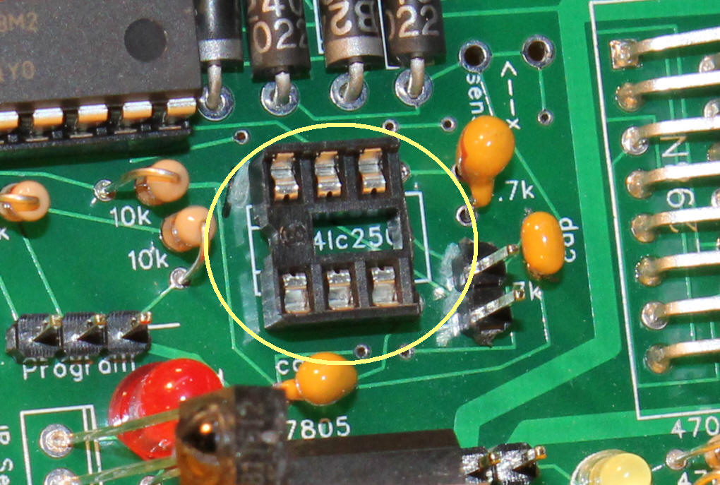
| Wiring the Circuit Start by building the circuit as described here: http://www.trainelectronics.com/PicaxeSpeedController/article The optoisolator will be installed in the space that is normally used for the memory chip that is covered in this article: http://www.trainelectronics.com/PicaxeSpeedController/recorder.htm A six pin socket fits into the front six holes where the eight pin memory socket would normally be mounted. If you don't have a six pin socket on hand you can just cut one from an eight pin or larger socket as I have done.
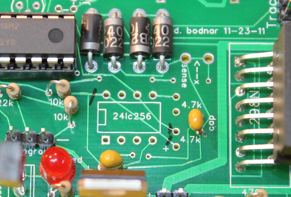
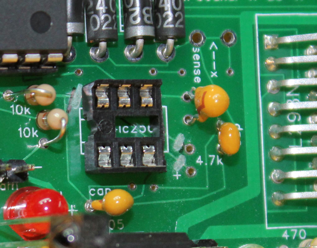
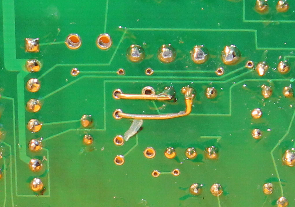
A number of traces on the circuit board need to be cut before installing the parts for the modification. I use a fine drill bit in a Dremel tool to cut traces but a sharp knife or razor blade will work, too. Just make sure that you go clear through the trace. If in doubt check with an ohm meter. Three traces need to be cut on the top of the board, they are marked in this photo...
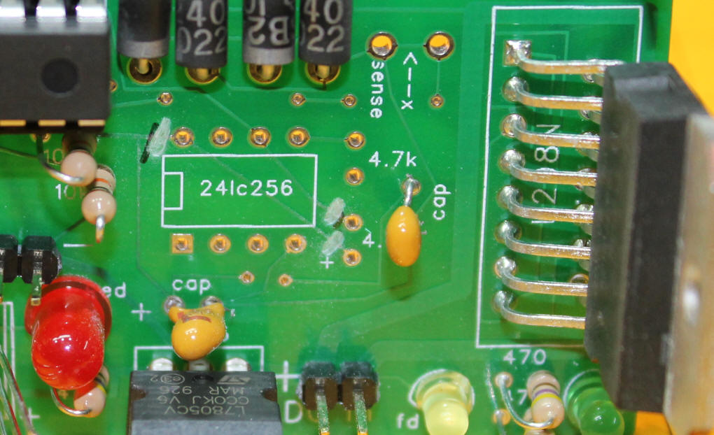
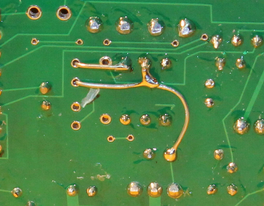
... and shown cut here.
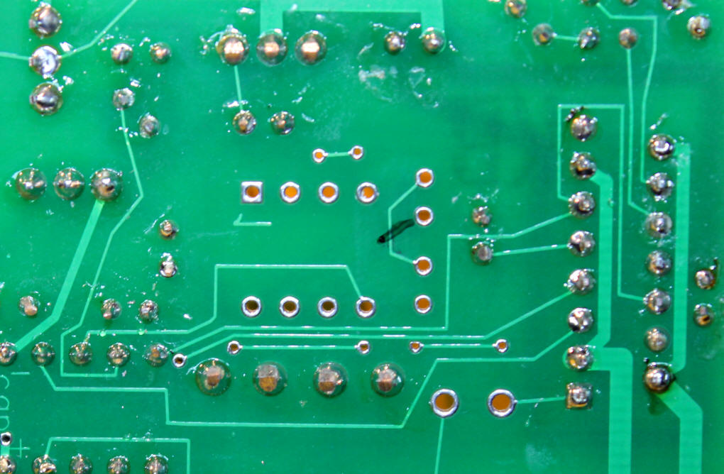
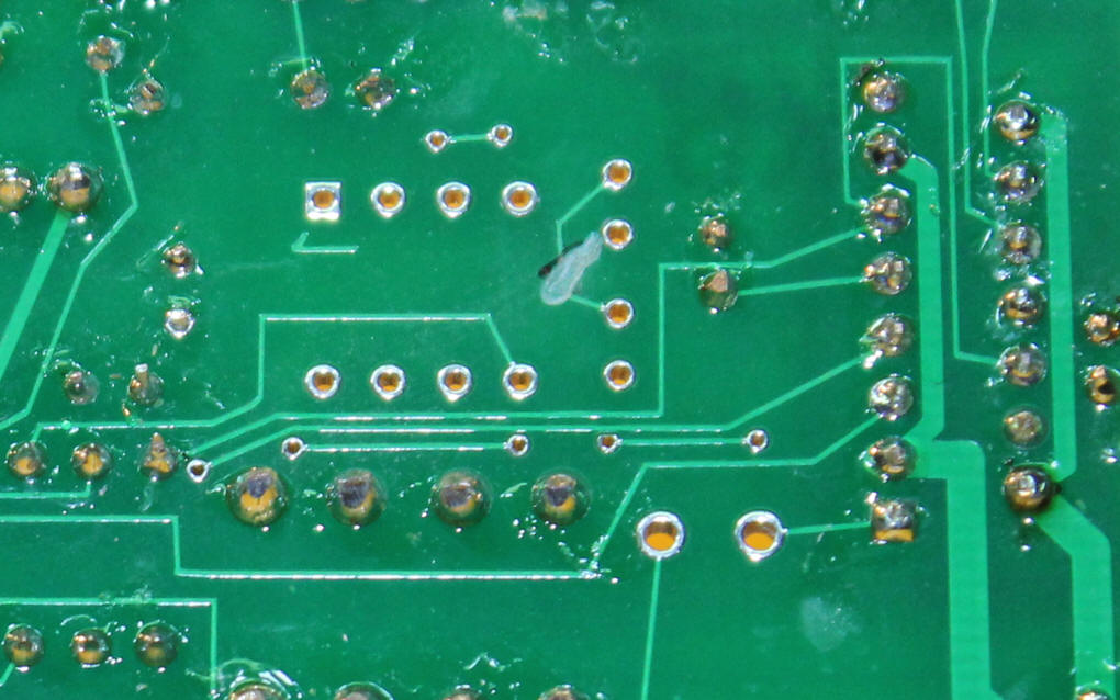
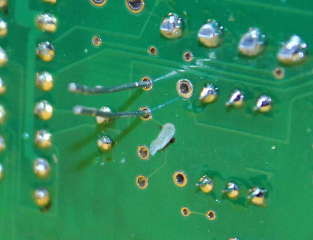
Here is the trace that needs to be cut on the back of the board.
|
| The schematic shows the new components that
are added in the upper right area. The input to the optoisolator
comes directly from the track pickups. The output from the
optoisolator goes to pin 10 on the PICAXE. Be sure to orient
the diodes as shown in the drawing. They are NOT installed in the
same manner as with a DC point-to-point where both diodes go in the same
direction.
|
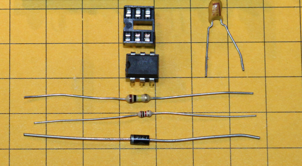
| Here are the parts that are needed for this
modification. A six pin socket, a 4N27, a 100K resistor, a 1K
resistor, a small diode and a 1 Mfd tantalum capacitor. The bridge
rectifier and capacitor are not shown in this photo.
|
Adding the Modification
Pull the leads through the back of the board but don't cut them off.
Bend the leads over and solder as shown. Take care that the top lead does not come in contact with the hole under the lead.
Solder a small scrap lead from an LED as shown here.
Insert the two pin header as shown here. Solder from the back.
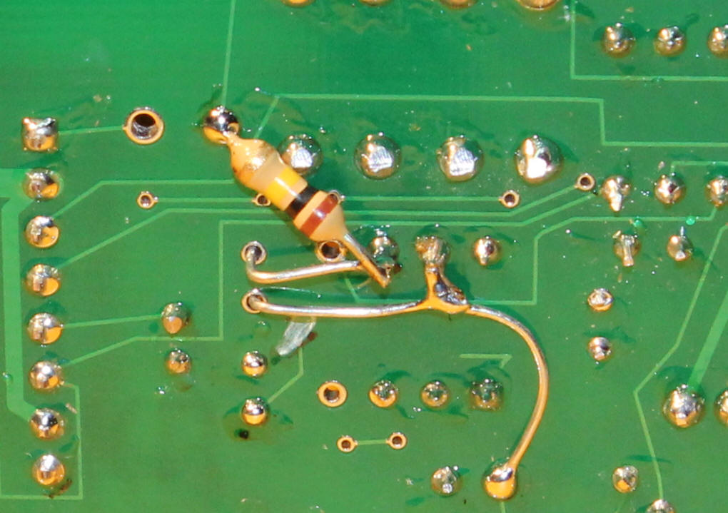
Add the 100K resistor.
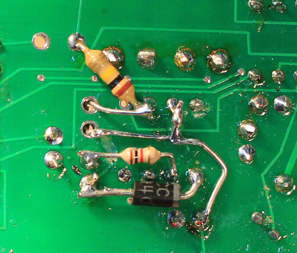
Then the 1K resistor and the diode. Note the orientation of the diode. Its band must point as shown.
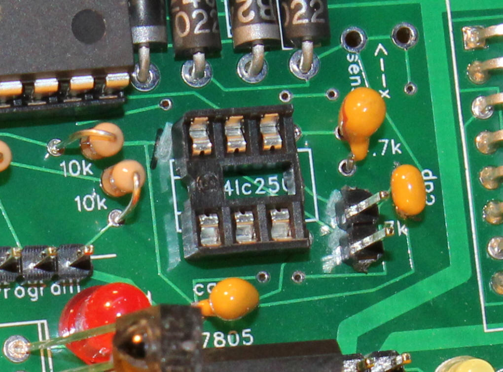
Here is a close-up of the finished modification.
|
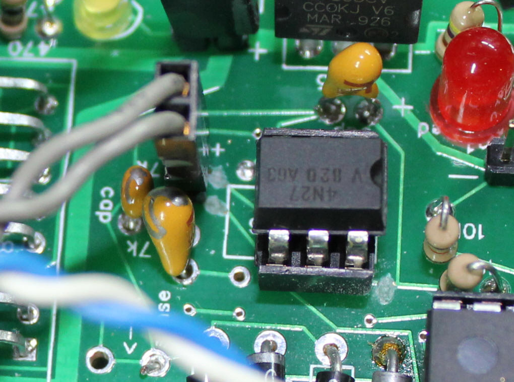
| Insert the 4N27 with the notch pointing away
from the L298N.
|
|
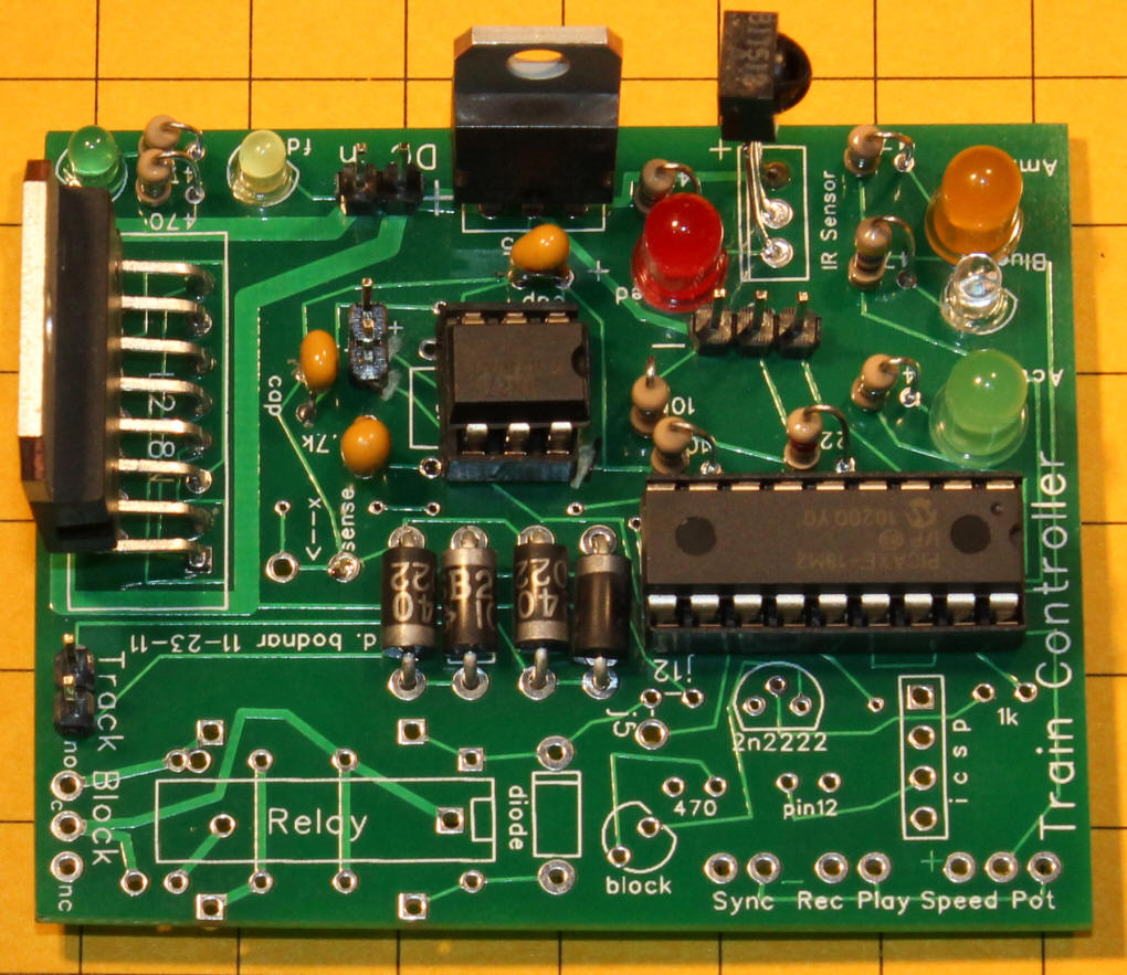
Here is the completed board.
|
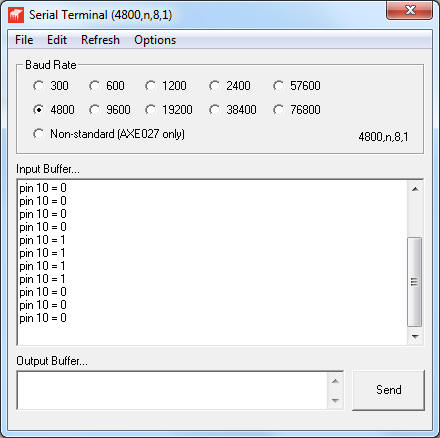
| Testing This short program can be used to test the circuit. Run the program and note the serial window that should show a continuous display of Pin 10 = 0
'd. bodnar - 12-15-2011 Apply a DC voltage to the pins next to the 4N27. When applied in one way the Pin 10 = 0 will continue, when switched + for - it should change to Pin 10 = 1. In addition the blue LED will light when pin 10 = 1.
|
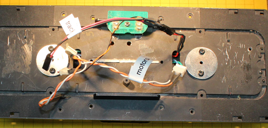
| Installation To install the unit in a trolley or locomotive you must isolate the wires that go to the wheels / track and those that go to the motor(s). The locomotive that I used for testing is shown below. It has two powered trucks and two sets of track pickups. I wired the motor leads in parallel making sure that the wheels turned in the same direction when I applied power. I did the same with the wheel pickup wires, again making sure that I connected the wheels so the all wheels on one side were wired together. In this photo the red/black wires go to the track pickups and the orange/white wires go to the motors.
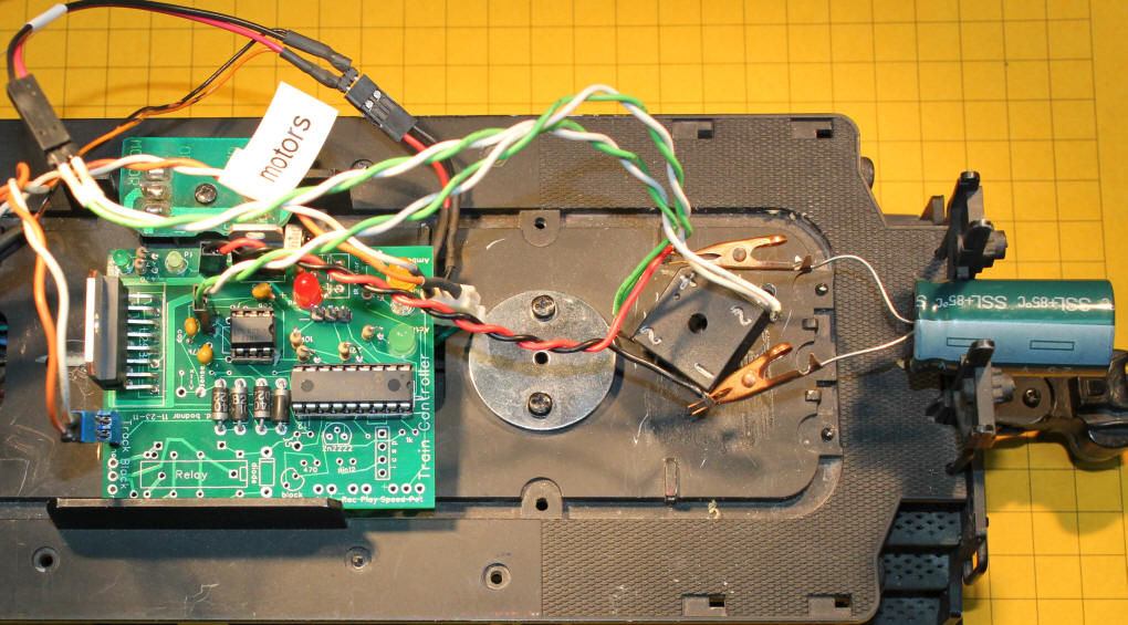
Connect the wheel pickup wires to the AC inputs on your bridge rectifier. These leads are generally marked with a symbol that looks like an "S" laying on its side. The output from the bridge rectifier is marked with a "+" for positive and a "-" for negative. You will also need to wire an electrolytic capacitor in parallel with the output making sure that you connect positive to positive and negative to negative. In this photo I was experimenting with various capacitor values using capacitors with clip leads to expedite testing. Make sure the voltage of the capacitor is at least 25 volts. The higher the microfarad rating the better. The cap shown here is 4700uF with a voltage rating of 25 volts. Its negative lead is marked with a silver line. The red/black wires will go to the power input pins on the PICAXE controller. One set of the green/white wires go to the track pickups. The other set of green/white go to the input to the optoisolator.
Here the PICAXE board and bridge rectifier/capacitor have been mounted temporally on the test locomotive. Place the locomotive on a track with diodes at each end with their bands pointing outwards, as shown in the schematic. Apply AC power to the track. I used an old Lionel transformer and applied about 15 volts AC. I have tested the circuit with up to 20 volts AC. Speed up the train with the TV remote control. When the locomotive reaches the diode section of track it should decelerate / stop / reverse and continue on its way. If it does not reverse the plug from the track power that goes to the optoisolator input pins and make sure the diodes are oriented properly on the track.
|
| Conclusion Every holiday season I run a trolley on a track on the railing in front of my house. During the 2011 holidays the trolley equipped with this modified controller ran flawlessly for 32 days, running up to 16 hours a day. It did not skip a beat, going back & forth more than 150 times each hour! I was looking for a good reliable system to run my holiday trolley and I think I have found it! |
|
Latest and Greatest Control Program The most up to date version of the software is here: LATEST PROGRAM and NOTES |